Page is loading ...

800-350-8739 MBRPMM106H Rev. A.1 Page 1
www.braveproducts.com
800-350-8739
MBRPMM106HA
Operator’s Safety & Service Manual
Mortar & Plaster Mixer
WARNING
READ and UNDERSTAND this manual completely, before using this Mortar & Plaster Mixer.
All operators of this equipment must read and completely understand all safety information, operating instructions,
maintenance and storage instructions. Failure to properly operate and maintain this Mortar & Plaster Mixer could result in
serious injury to the operator.
• WARNING: Wear appropriate protective gear. This list includes, but is not limited to:
- A hard hat
- Protective boots with slip resistant soles
- Protective goggles
- Heavy gloves
- Hearing protection
• DANGER: Keep riders off machine. Riders can be seriously injured or killed by entanglement or by falling.
• WARNING: Rotating part hazard always stand clear of the dump handle when mixer is in operation. Any binding of material
between mixer blades and the drum may cause drum handle to quickly move to the charge position.
• WARNING: LETHAL EXHAUST GAS! An internal combustion engine discharges carbon monoxide, which is a poisonous and
odorless invisible gas. Death or serious illness may result if inhaled. Operate only in an area with good ventilation.
• DANGER: Use extreme caution when storing, handling and using fuels - they are highly volatile and explosive in the vapor
state. Do not add fuel while engine is running. Stop and cool the engine before adding fuel.
• WARNING: Excessive towing speed can cause serious injuries or death. Do not exceed 45 mph. (73KM/HR)
• WARNING: Stop engine, disconnect spark plug wire and wait for all moving parts to stop before servicing, maintaining,
cleaning or making any adjustments.
• WARNING: Do not place hands in the drum unless engine is off and spark plug is disconnected.
• DANGER: Do not smoke when refueling.
• WARNING: Stay away from hot engine components during operation.
• WARNING: Always attach safety chain when towing.
• WARNING: Install, close, and secure all guards, shields and hoods before operating.
STOP!
ADD OIL TO ENGINE BEFORE USING: Engine is shipped without oil. DO NOT start engine without first adding oil.
INSPECT COMPONENTS: Closely inspect to make sure no components are missing or damaged.
See Initial Unpacking and assembly instructions and for whom to contact to report missing or damaged parts.
Any Questions, Comments, Problems or Parts Orders
Call BRAVE Product Support 1-800-350-8739
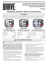
ITEM NUMBERS: BRPMM106H, BRPMM206H,
BRPMM108H, BRPMM208H

800-350-8739 MBRPMM106H Rev. A.1 Page 2
www.braveproducts.com
800-350-8739
TABLE OF CONTENTS
1. Serial Number Location ............................................. 3
2. Parts Ordering Procedure ......................................... 3
3. Assembly Instructions ............................................ 4-6
4. Safety Precaution ...................................................... 7
5. Safety Notice & Decals ........................................... 8-9
6. Safety Decal Location ......................................... 10-11
7. Before Operating ................................................ 11-12
8. Operating Instructions ...................................... 12-13
9. Adding Fluids & Towing ........................................... 13
10. Service Instructions ............................................... 14
11. Maintenance Schedule .......................................... 14
12. Replacements ........................................................ 15
13. Equipment General Specs ................................ 15-16
14. Torque Chart ......................................................... 17
15. Parts Breakdown .............................................. 18-31
16. Warranty………………….…………………………………………32
17. Warranty Registration…………………………………………33
It is the OWNER´S RESPONSABILITY to communicate information on the
SAFE USE and OPERATION of this machine to the operators.

800-350-8739 MBRPMM106H Rev. A.1 Page 3
www.braveproducts.com
800-350-8739
1. SERIAL NUMBER LOCATION
The model/serial number decal is located on the shroud assembly (cowl).
(Write model number)
(Write serial number)
The unit year of manufacturing can be determined by its serial number. So, keep this
information handy at all times, use your unit serial number when ordering parts.
This Unit warranty is stated in this Operational and Safety manual on page 32. Failure to return
warranty registration card renders the warranty null and void.
An engine owner’s manual is also attached to every unit. Engine parts must be order from any
authorized HONDA dealer. Refer to the engine owner´s manual lo learn about specifications
and part identification.
2. PARTS ORDERING PROCEDURE:
Parts must be ordered through your local dealer or by contacting Brave Customer Service at
800-350-8739. If you can’t locate a local dealer in your area visit us online at
www.braveproducts.com to locate the nearest dealer.
All HONDA warranties and parts ordering must be through your Honda dealers.
Please visit https://engines.honda.com/dealer-locator for more information.
REMEMBER – You own the best Mixer. If repairs are needed, use
only OEM purchased parts from authorized dealers.
ALWAYS HAVE READY:
1. Applicable model and serial number of machine(s).
2. Item part number(s), description, and quantity.

800-350-8739 MBRPMM106H Rev. A.1 Page 4
www.braveproducts.com
800-350-8739
3. ASSEMBLY INSTRUCTIONS (MIXER STANDING ON END)
1. Fully unpack unit, cut straps, remove all cardboard, plastic wrap and all protecting
packing material from unit.
You will see:
• (2) Wheels
• (1) Axle assembly with speed hubs and wheel lugs bolted
on
• (1) Idler spring attached into axle tab
• (1) Towing hitch with quick pin and a hex bolt with nut
• (1) Dumping lever zip tied in the inside of the drum with
hardware installed but not tight.
2. Once the mixer is unpacked proceed to attach the mixer’s axle making sure that the axle
spring tab lines up with the mixer frame hole on the engine base of the machine.
3. Proceed to fasten axle to mixer frame using appropriate tools. Tighten to 57 ft. lbs.
4. Once mixer axle is fastened, hook both ends of idler spring, the rounded end to the
farthest out hol on axle and the oval end to the idler pulley (clutch) on the inside of the
engine base.

800-350-8739 MBRPMM106H Rev. A.1 Page 5
www.braveproducts.com
800-350-8739
5. Unscrew all (8) wheel lug nuts from axle wheel hubs and mount wheels making sure the
air valve is facing outside.
6. Proceed to fasten wheel lug nut at no more than 105 ft. lbs.
7. Once wheels are fastened proceed to remove hardware that holds machine to pallet
using a 9/16 wrench and/or deep socket.
8. Once pallet hardware is removed and using appropriate equipment, safely place the
mixer upright on the tires/ground.
Warning: failure to use proper lifting equipment could cause mixer to fall
and cause serious injury.

800-350-8739 MBRPMM106H Rev. A.1 Page 6
www.braveproducts.com
800-350-8739
9. Once mixer is upright on the ground proceed to install the drum Dumping lever, make
sure the ergonomic grip is facing right direction and outward for dumping.
10. Install mixer 2” ball coupling, tow pole assembly into mixer receiver and install bolt &
nut in the hole behind the receiver and the bolt & hairpin through the receiver.
Tow pole bolt & nut Bolt & hairpin One piece safety

800-350-8739 MBRPMM106H Rev. A.1 Page 7
www.braveproducts.com
800-350-8739
4. SAFETY PRECAUTIONS
READ AND STUDY THE FOLLOWING SAFETY INFORMATION BEFORE ATTEMPTING TO OPERATE THIS
EQUIPMENT. IN ADDITION, ENSURE THAT EVERY INDIVIDUAL WHO OPERATES OR WORKS WITH THIS
EQUIPMENT IS FAMILIAR WITH THESE SAFETY PRECAUTIONS.
WARNING - LETHAL EXHAUST GAS!
An internal combustion engine discharges carbon monoxide, which is a
poisonous and odorless invisible gas. Death or serious illness may result if
inhaled. Operate only in an area with good ventilation.
NEVER IN A CONFINED AREA!
WARNING - DANGEROUS FUELS!
Use extreme caution when storing, handling and using fuels - they are highly volatile
and explosive in the vapor state. Do not add fuel while engine is running. Stop and
cool the engine before adding fuel.
DO NOT SMOKE WHEN REFUELING!
SAFETY GUARDS
It is the owner's responsibility to ensure ALL GUARDS AND SHIELDS are in place and in working order.
DRESS SAFE - DO NOT WEAR loose clothing, rings, wristwatches, etc., near machinery.
NOISE PROTECTION
Wear O.S.H.A. specified hearing protection devices.
FOOT PROTECTION
Wear O.S.H.A. specified steel tip safety shoes.
HEAD PROTECTION
Wear O.S.H.A. specified safety helmets.
EYE PROTECTION
Wear O.S.H.A. specified eyes shields, safety glasses, and sweat bands.
DUST PROTECTION
Wear O.S.H.A. specified dust mask or respirator.
OPERATOR
Keep children and bystanders off and away from the equipment.
For details on safety rules and regulations in the United States, contact your local Occupational Safety
and Health Administration (O.S.H.A.) office. Equipment operated in other countries must be operated
and serviced in accordance and compliance with any and all safety requirements of such country. The
publication of these safety precautions is done for your information does not by the publication of
these precautions, imply or in any way represent that these are the sum of all dangers present near
equipment. If you are operating this unit it is your responsibility to ensure that such operation is in full
accordance with all applicable safety requirements and codes. All requirements of the United States
Federal Occupational Safety and Health Administration Act must be met when operated in areas that
are under the jurisdiction of that United States Department.

800-350-8739 MBRPMM106H Rev. A.1 Page 8
www.braveproducts.com
800-350-8739
5. SAFETY NOTICE & DECALS
IMPORTANT NOTICE
The "SAFETY ALERT SYMBOL" is used to call attention to items or operations that may be dangerous
to those operating or working with this equipment. These symbols can be found throughout the
manual and on the unit itself. Please read these warnings and cautions carefully.
READ SAFETY DECALS CAREFULLY
Carefully read and follow all safety decals. Keep them in good conditions. If they become aged,
replace as required. If repainting, REPLACE ALL decals. Decals are available from your
authorized dealers. Decals are not shown to scale.
CAUTION
WHEN TOWING, ENSURE
DRAWBAR IS IN THE
MIDDLE POSITION.
201012
CAUTION
2-PERSON LIFT REQUIRED
TO POSITION MIXER HITCH
ON/OFF VEHICLE
201155
WARNING
ROTATING PART HAZARD
ALWAYS STAND CLEAR OF THE DUMP HANDLE
WHEN MIXER IS IN OPERATION. ANY BINDING OF
MATERIAL BETWEEN MIXER BLADES AND THE
DRUM MAY CAUSE DRUM HANDLE TO QUICKLY
MOVE TO THE CHARGE POSITION.
201157
NOTICE
•
ENSURE THE VEHICLE HAS TOWING CAPACITY FOR THE WEIGHT OF THIS
MACHINE.
•DO NOT TOW MACHINE UNLESS THE DRAW BAR IS BOLTED IN PLACE AND THE
SAFETY PIN IS SECURELY FASTENED.
•CLOSE ENGINE FUEL CUTOFF BEFORE TOWING MIXER TO PREVENT LEAKING OIL
INTO ENGINE CRANKCASE.
•2-PERSON LIFT PER UNIT TO POSITION MIXER ON VEHICLE.
•SECURELY ATTACH HITCH TO TOWING VEHICLE. ENSURE USE OF SAFETY PIN
THROUGH LATCH OR HANDWHEEL FOR BALL TYPE HITCH.
•SAFETY CHAIN ATTACHMENT (SEE PICTURE) MUST CROSS UNDER THE DRAW
BAR AND BE POSITIONED TO PREVENT THE DRAW BAR FROM DROPPING TO THE
GROUND IN THE EVENT OF HITCH FAILURE.
•CONNECT LIGHTING PLUG/ELECTRIC BRAKE PLUG
(WHEN APPLICABLE)
•MAKE CERTAIN THAT THE WHEEL LUG NUTS AND
AXLE MOUNT HARDWARE IS TIGHTENED.
•CHECK PRESSURE AND OVERALL CONDITION
OF TIRES.
•TEST BREAKS (IF APPLICABLE)
201150
201354

800-350-8739 MBRPMM106H Rev. A.1 Page 9
www.braveproducts.com
800-350-8739
6. DECAL LOCATION
EXCESSIVE TOWING SPEED CAN CAUSE SERIOUS
INJURIES OR DEATH.
DO NOT EXCEED 45 MI/HR. (73 KM/HR.)
•BE CERTAIN THAT THE WHEEL LUG NUTS AND AXLE
MOUNTING HARDWARE ARE TIGHTENED.
•CHECK PRESSURE AND OVERALL CONDITIONS OF
TIRES.
201151
WARNING
WARNING
ROTATING PART HAZARD
KEEP AWAY
TO PREVENT SERIOUS INJURY OR DEATH ROTATING PARTS:
1. INSTALL, CLOSE AND SECURE ALL GUARDS, SHIELDS
AND HOODS BEFORE OPERATING.
2. DO NOT PLACE HANDS IN DRUM UNLESS THE
MOTOR OR ENGINE IS OFF AND THE POWER CORD
UNPLUGGED OR THE KILL SWITCH ACTIVATED.
3. KEEP HANDS, FEET, HAIR AND LOOSE CLOTHES
AWAY FROM MOVING PARTS.
201003
WARNING
1. READ AND UNDERSTAND OPERATOR’S MANUAL AND SAFETY SIGNS BEFORE
STARTING.
2. STOP ENGINE, DISCONNECT SPARK PLUG WIRE AND WAIT FOR ALL MOVING
PARTS TO STOP BEFORE SERVICING, MAINATAINING, ADJUSTING OR CLEANING.
3. KEEP HANDS, FEET, HAIR OR CLOTHING AWAY FROM MOVING PARTS.
4. INSTALL, CLOSE AND SECURE ALL GUARDS, SHIELDS AND HOODS BEFORE
OPERATING.
5. DO NOT PLACE HANDS IN THE DRUM UNLESS ENGINE IS OFF AND SPARK
PLUG IS DISCONNECTED OR MOTOR IS OFF AND POWER CORD IS UNPLUGGED.
6. STAY AWAY FROM HOT ENGINE COMPONENTS DURING OPERATION
7. HAVE A LICENCED ELECTRICIAN WIRE UP ELECTRIC MOTORS.
8. DO NOT SMOKE WHEN REFUELING.
9. USE POWER CORD WITH REQUIRED CAPACITY TO CARRY POWER TO ELECTRIC
MOTOR.
10. FOLLOW GOOD SAFETY PROCEDURES WHEN HANDLING FUEL.
11. ROUTE THE POWER CORD OUT OF THE WAY & PROTECT IT FROM DAMAGE.
12. DO NOT OPERATE IN AN EXPLOSIVE ATMOSPHERE OR A POORLY
VENTILATED AREA WITHOUT ADEQUATE VENTILATION.
13. KEEP WORKING AREAS DRY AND CLEAN TO PREVENT SLIPPING AND
TRIPPING.
14. ALWAYS ATTACH SAFETY CHAIN WHEN TOWING.
15. COMPLY WITH APPLICABLE TRANSPORTING REGULATIONS WHEN TOWING.
16. DO NOT ALLOW RIDERS DURING TRANSPORTING.
17. DO NOT EXCEED A SAFETY TRAVEL SPEED WHEN TRANSPORTATING.
SLOW DOWN FOR CORNERS AND WHEN GOING OVER ROUGH TERRAIN.
201001
CHECK LIST
CHECK AND TIGHTEN WHEN NECESSARY ALL NUTS AND BOLTS.
CHECK MIXER PADDLE AND WIPERS ADJUSTMENTS AND TIGHTEN
PADDLE BOLTS.
GREASE ALL FITTINGS – GREASE DRUM SEALS TO AVOID DOWN
TIME ON REPAIRS.
CHECK BELT ADJUSTMENT AND TIGHTEN BELT IF NECESSARY.
CHECK TIRE PRESSURE. INFLATE 12” AND 13” TO 30 PSI. 8” TIRES TO
45 PSI. WHEEL LUG TORQUE MUST BE 105 LBF.
ENSURE THE DRUM LOCK AND HOOD FASTENER ARE IN LOCKED
POSITION BEFORE TRANSPORTATION.
290791
WARNING
MISSING GUARD HAZARD
INSTALL, CLOSE AND SECURE ALL GUARDS,
SHIELDS AND HOODS BEFORE OPERATING.
201004
WARNING
IMPROPER OPERATION OF THIS EQUIPMENT CAN
CAUSE SERIOUS INJURY OR DEATH.
READ OPERATOR’S MANUAL SUPPLIED WITH THIS
MACHINE BEFORE OPERATION OR SERVICING.
MODIFICATION OR ALTERATION OF THIS MACHINE
WILL VOID MANUFACTURER’S WARRANTY.
DO NOT ALTER OR MODIFY THIS MACHINE WITHOUT
THE EXPRESS WRITTEN CONSENT OF THE
MANUFACTURER.
201154
EMERGENCY STOP
PUSH TO STOP
201026
WARNING
MISSING GUARD HAZARD
INSTALL, CLOSE AND SECURE
ALL GUARDS, SHIELDS AND
HOODS BEFORE OPERATING.
201004
WARNING
ROTATING PART HAZARD
KEEP AWAY
TO PREVENT SERIOUS INJURY OR DEATH ROTATING PARTS:
1. INSTALL, CLOSE AND SECURE ALL GUARDS, SHIELDS AND
HOODS BEFORE OPERATING.
2. DO NOT PLACE HANDS IN DRUM UNLESS THE MOTOR OR
ENGINE IS OFF AND THE POWER CORD UNPLUGGED OR THE
KILL SWITCH ACTIVATED.
3. KEEP HANDS, FEET, HAIR AND LOOSE CLOTHES AWAY FROM
MOVING PARTS.
WARNING

800-350-8739 MBRPMM106H Rev. A.1 Page 10
www.braveproducts.com
800-350-8739
WARNING
1. READ AND UNDERSTAND OPERATOR’S MANUAL AND SAFETY SIGNS BEFORE
STARTING.
2. STOP ENGINE, DISCONNECT SPARK PLUG WIRE AND WAIT FOR ALL MOVING
PARTS TO STOP BEFORE SERVICING, MAINATAINING, ADJUSTING OR CLEANING.
3. KEEP HANDS, FEET, HAIR OR CLOTHING AWAY FROM MOVING PARTS.
4. INSTALL, CLOSE AND SECURE ALL GUARDS, SHIELDS AND HOODS BEFORE
OPERATING.
5. DO NOT PLACE HANDS IN THE DRUM UNLESS ENGINE IS OFF AND SPARK
PLUG IS DISCONNECTED OR MOTOR IS OFF AND POWER CORD IS UNPLUGGED.
6. STAY AWAY FROM HOT ENGINE COMPONENTS DURING OPERATION
7. HAVE A LICENCED ELECTRICIAN WIRE UP ELECTRIC MOTORS.
8. DO NOT SMOKE WHEN REFUELING.
9. USE POWER CORD WITH REQUIRED CAPACITY TO CARRY POWER TO ELECTRIC
MOTOR.
10. FOLLOW GOOD SAFETY PROCEDURES WHEN HANDLING FUEL.
11. ROUTE THE POWER CORD OUT OF THE WAY & PROTECT IT FROM DAMAGE.
12. DO NOT OPERATE IN AN EXPLOSIVE ATMOSPHERE OR A POORLY
VENTILATED AREA WITHOUT ADEQUATE VENTILATION.
13. KEEP WORKING AREAS DRY AND CLEAN TO PREVENT SLIPPING AND
TRIPPING.
14. ALWAYS ATTACH SAFETY CHAIN WHEN TOWING.
15. COMPLY WITH APPLICABLE TRANSPORTING REGULATIONS WHEN TOWING.
16. DO NOT ALLOW RIDERS DURING TRANSPORTING.
17. DO NOT EXCEED A SAFETY TRAVEL SPEED WHEN TRANSPORTATING.
SLOW DOWN FOR CORNERS AND WHEN GOING OVER ROUGH TERRAIN.
201001
WARNING
IMPROPER OPERATION OF THIS EQUIPMENT CAN
CAUSE SERIOUS INJURY OR DEATH.
READ OPERATOR’S MANUAL SUPPLIED WITH THIS
MACHINE BEFORE OPERATION OR SERVICING.
MODIFICATION OR ALTERATION OF THIS MACHINE
WILL VOID MANUFACTURER’S WARRANTY.
DO NOT ALTER OR MODIFY THIS MACHINE WITHOUT
THE EXPRESS WRITTEN CONSENT OF THE
MANUFACTURER.
201154
CHECK LIST
CHECK AND TIGHTEN WHEN NECESSARY ALL NUTS AND BOLTS.
CHECK MIXER PADDLE AND WIPERS ADJUSTMENTS AND TIGHTEN PADDLE BOLTS.
GREASE ALL FITTINGS – GREASE DRUM SEALS TO AVOID DOWN TIME ON REPAIRS.
CHECK BELT ADJUSTMENT AND TIGHTEN BELT IF NECESSARY.
CHECK TIRE PRESSURE. INFLATE 12” AND 13” TO 30 PSI. 8” TIRES TO 45 PSI.
ENSURE THE DRUM LOCK AND HOOD FASTENER ARE IN LOCKED POSITION BEFORE
TRANSPORTATION.
290791
WARNING
1. READ AND UNDERSTAND OPERATOR’S MANUAL AND SAFETY SIGNS BEFORE STARTING.
2. STOP ENGINE, DISCONNECT SPARK PLUG WIRE AND WAIT FOR ALL MOVING PARTS TO
STOP BEFORE SERVICIN G, MAINATAINING, ADJUSTING OR CLEANING.
3. KEEP HANDS, FEET, HAIR OR CLOTHING AWAY FROM MOVING PARTS.
4. INSTALL, CLOSE AND SECURE ALL GUARDS, SHIELDS AND HOODS BEFORE OPERATING.
5. DO NOT PLACE HANDS IN THE DRUM UNLESS ENGINE IS OFF AND SPARK PLUG IS
DISCONNECTED OR MOTOR IS OFF AND POWER CORD IS UNPLUGGED.
6. STAY AWAY FROM HOT ENGINE COMPONENTS DURING OPERATION
7. HAVE A LICENCED ELECTRICIAN WIRE UP ELECTRIC MOTORS.
8. DO NOT SMOKE WHEN REFUELING.
9. USE POWER CORD WITH REQUIRED CAPACITY TO CARRY POWER TO ELECTRIC MOTOR.
10. FOLLOW GOOD SAFETY PROCEDURES WHEN HANDLING FUEL.
11. ROUTE THE POWER CORD OUT OF THE WAY & PROTECT IT FROM DAMAGE.
12. DO NOT OPERATE IN AN EXPLOSIVE ATMOSPHERE OR A POORLY VENTILATED AREA
WITHOUT ADEQUATE VENTILATION.
13. KEEP WORKING AREAS DRY AND CLEAN TO PREVENT SLIPPING AND TRIPPING.
14. ALWAYS ATTACH SAFETY CHAIN WHEN TOWING.
15. COMPLY WITH APPLICABLE TRANSPORTING REGULATIONS WHEN TOWING.
16. DO NOT ALLOW RIDERS DURING TRANSPORTING.
17. DO NOT EXCEED A SAFETY TRAVEL SPEED WHEN TRANSPORTATING.
SLOW DOWN FOR CORNERS AND WHEN GOING OVER ROUGH TERRAIN.
201001

800-350-8739 MBRPMM106H Rev. A.1 Page 11
www.braveproducts.com
800-350-8739
7. BEFORE OPERATING
• REMEMBER! It is the owner´s responsibility to communicate information on the safe
use and proper operation of this unit to the operators.
• Before operating, review SAFETY PRECAUTIONS listed on page 7 of this manual.
• Familiarize yourself with the operation of the unit and confirm that all controls function
properly BEFORE starting engine.
• Locate the kill switch and assure you know how to STOP the unit.
• Make sure hands, feet, and clothing are at a safe distance from any moveable parts prior
to starting.
• Shrouds and grids are provided to protect the operator or structures in close proximity
to rotating hot engine parts. It is the RESPONSIBILITY OF THE OPERATOR to see that
they are properly in place.
• OIL LEVEL - Check the oil level in the engine. For more information see "Lubrication"
under the engine "Owner's Manual" the "Maintenance" section of this manual.
WARNING
ROTATING PART HAZARD
ALWAYS STAND CLEAR OF THE DUMP HANDLE
WHEN MIXER IS IN OPERATION. ANY BINDING OF
MATERIAL BETWEEN MIXER BLADES AND THE
DRUM MAY CAUSE DRUM HANDLE TO QUICKLY
MOVE TO THE CHARGE POSITION.
201157
NOTICE
•ENSURE THE VEHICLE HAS TOWING CAPACITY FOR THE WEIGHT OF
THIS MACHINE.
•DO NOT TOW MACHINE UNLESS THE DRAW BAR IS BOLTED IN PLACE
AND THE SAFETY PIN IS SECURELY FASTENED.
•CLOSE ENGINE FUEL CUTOFF BEFORE TOWING MIXER TO PREVENT
LEAKING OIL INTO ENGINE CRANKCASE.
•2-PERSON LIFT PER UNIT TO POSITION MIXER ON VEHICLE.
•SECURELY ATTACH HITCH TO TOWING VEHICLE. ENSURE USE OF
SAFETY PIN THROUGH LATCH OR HANDWHEEL FOR BALL TYPE HITCH.
•SAFETY CHAIN ATTACHMENT (SEE PICTURE) MUST CROSS UNDER THE
DRAW BAR AND BE POSITIONED TO PREVENT THE DRAW BAR FROM
DROPPING TO THE GROUND IN THE EVENT OF HITCH FAILURE.
•CONNECT LIGHTING PLUG/ELECTRIC BRAKE PLUG
(WHEN APPLICABLE)
•MAKE CERTAIN THAT THE WHEEL LUG NUTS AND
AXLE MOUNT HARDWARE IS TIGHTENED.
•CHECK PRESSURE AND OVERALL CONDITION
OF TIRES.
TEST BREAKS (IF APPLICABLE)
201150
WARNING
EXCESSIVE TOWING SPEED CAN CAUSE SERIOUS
INJURIES OR DEATH.
DO NOT EXCEED 45 MI/HR. (73 KM/HR.)
•BE CERTAIN THAT THE WHEEL LUG NUTS AND AXLE
MOUNTING HARDWARE ARE TIGHTENED.
•CHECK PRESSURE AND OVERALL CONDITIONS OF
TIRES.
201151
CAUTION
WHEN TOWING, ENSURE
DRAWBAR IS IN THE MIDDLE
POSITION. 201012
CAUTION
2-PERSON LIFT REQUIRED TO
POSITION MIXER HITCH
ON/OFF VEHICLE 201155
WARNING
ROTATING PART HAZARD
KEEP AWAY
TO PREVENT SERIOUS INJURY OR DEATH ROTATING PARTS:
1. INSTALL, CLOSE AND SECURE ALL GUARDS, SHIELDS AND
HOODS BEFORE OPERATING.
2. DO NOT PLACE HANDS IN DRUM UNLESS THE MOTOR
OR ENGINE IS OFF AND THE POWER CORD UNPLUGGED
OR THE KILL SWITCH ACTIVATED.
3. KEEP HANDS, FEET, HAIR AND LOOSE CLOTHES AWAY
FROM MOVING PARTS.
201003

800-350-8739 MBRPMM106H Rev. A.1 Page 12
www.braveproducts.com
800-350-8739
All mixers come without oil in ENGINE AND GEAR REDUCER COMPARTMENT. GX240
ENGINES W/ 6:1 REDUCER BOX has TWO (2) oil compartments. Running an engine
without lubrication may damage this unit.
• AIR CLEANER - Check to ensure elements are in good condition and properly installed.
• Review every decal with the OPERATOR.
• FUEL SUPPLY – Mixer engines require an automotive grade of clean, fresh, unleaded
gasoline. All mixers come WITHOUT gasoline, oil or any other fluid.
• LUBRICATION POINTS - Make sure all pillow blocks and drum’s trunnions have been
properly greased.
• PADDLES AND BLADES - Check the paddles wipers and make sure they are adjusted to
about 3/16" interference with the drum. This is mandatory after installing rubber blades
on the paddles. Wipers can be adjusted at a desired position.
8. OPERATION INSTRUCTIONS
Prior to starting engine, make sure mixer engagement lever is in the "IDLE" POSITION, and drum
is complete lock on its mix/tow position.
Check Gas engine
1. Open the fuel valve.
2. Pull the stop switch on the engine shroud to its "Out" position.
3. Move the engine throttle control to the "FAST" position.
4. Move Choke lever to the choke position, located on the engine.
5. Pull the starter recoil briskly.
6. After the engine starts, move the choke lever to the open position, move the throttle
level to the "IDLE" position and let the engine warm-up for one or two minutes.
Check Electric motor
1. Plug the motor into a suitable power source, according to the motor specs.
2. Move the switch on the motor to the "on" position.
OPERATING
1. Make sure the engagement lever is on the "IDLER" position.
2. Make sure the drum is locked in to avoid drum from flipping over before running engine.
3. Pull the stop switch on the engine shroud to its "Out" position.
4. Pull the engine starter recoil briskly.
5. Close the engine shroud
DO NOT OPERATE THE MIXER WITH THE SHROUD OPEN!
GX240 6:1 RED
ENGINE OIL FILLER

800-350-8739 MBRPMM106H Rev. A.1 Page 13
www.braveproducts.com
800-350-8739
6. Move the engagement lever into the "MIX" position and load the mixer.
Do not pour material before paddles are spinning, this can result on mixer damage and
will void the unit warranty.
7. After loading a batch of mortar, it is recommended to add water before adding a second
bag.
8. After discharging the final batch of mortar, add water to the drum while the mixer is
running. Discharge the water after to clean excess material.
9. Additional cleaning may be needed.
9. ADDING FLUIDS AND TOWING
GAS ENGINE
1. Move the engagement lever to the "IDLER" position and lock drum.
2. Turn the stop switch to the off position located on the engine shroud.
3. Close the fuel valve, located on engine.
4. Add oil, if needed to continue operation / Drain oil if need oil change.
5. Add gasoline if needed.
STOP THE ENGINE OR ELECTRIC MOTOR BEFORE:
1. Adding fuel/Oil.
2. Leaving equipment unattended for any amount of time.
3. Making any repairs or adjustments to the unit.
4. Transportation.
BEFORE TOWING:
1. Make sure the axle and tow bar hardware are tight.
2. Check the condition of the pin on the tow bar and make sure it is secured.
3. Remove any loose debris from the mixer.
4. Use safety chains when towing.
TOWING:
1. Stop the engine or electric motor.
2. Close and hook the engine should.
3. Rotate the drum into the tow position and secured it with the locking pin.
4. Secure the mixer hitch and safety chains to the vehicle.
MAXIMUM TOW SPEED: 45 mph (72 Km/h)

800-350-8739 MBRPMM106H Rev. A.1 Page 14
www.braveproducts.com
800-350-8739
10. SERVICE INSTRUCTIONS
• Never service or lubricate the unit engine while running.
• After servicing the unit, restore and fasten all guards, shields, and covers to their original
positions.
• Never drain oil into the ground, into open streams, or down sewage drains.
ENGINE
See engine owner´s manual maintenance schedule.
If lost please visit https://engines.honda.com/parts-and-support/owners-manuals for more
information.
DRUM
1. Wash the drum after every day’s usage.
2. Pull the locking pin and tip the drum forward to drain water excess.
3. Leave mixer drum facing down to avoid rainwater, snow, dust or any other weather
particles to get inside the mixer drum when not in use.
4. Secure with locking pin before moving mixer for towing or storing.
LUBRICATION
1. Grease all fittings daily. All mixers have 6 grease fittings, 4 pillow blocks and 2 drum
trunnions. Two of the fittings are located at each end of the mixer drum on the top of
pillow blocks and trunnions.
The two remaining grease fittings are located under the engine shroud on the top of the
intermediate shaft pillow blocks.
2. Electric mixers only: oil the drive chain once a week.
11. MAINTENANCE SCHEDULE
Maintenance
Each
use
Every
20 hours
Every
50 hours
Every
100 hours
Yearly
Engine
Refer to engine operator/owner manual
X
X
Bearings
Grease
X
X
V-Belts
Check for excessive wear
X
X
Hardware
Check and tighten 1,2
X
X
X
Tires
Check air pressure
X
1. Check all hardware after the first 5 hours of use, the follow the maintenance schedule.
2. Re-torque the front leg and axle hardware after the first 50 miles traveled, and then
follow the maintenance schedule.

800-350-8739 MBRPMM106H Rev. A.1 Page 15
www.braveproducts.com
800-350-8739
12. REPLACEMENT
Parts
Tolerance or Replacement Cycle
Engine Components
Refer to your engine manufacturer´s Owner´s
Manual
V-Belts
Replace if stretched to the point that the idler does
not work properly. Replace the V-belts if they are
cracked or torn.
Gears
Replace if the teeth are cracked or have become
sharp.
Hardware
Re-torque all bolts after the first eight hours of
operation and check hardware every 25 hours.
Replace any worn or damaged hardware as needed.
Replacement hardware should be grade 5 and zinc
plated.
Safety Decals
Replace if they become aged, damaged or cannot
be easily read.
13. EQUIPMENT SPECS
BRPMM Gas RPM = 31.15
X
Y
Z
BRPMM106H
28”
27-11/16”
24-1/16”
BRPMM108H
28”
30-3/4”
27-1/2”

800-350-8739 MBRPMM106H Rev. A.1 Page 16
www.braveproducts.com
800-350-8739
MODEL – Steel Drum
BRPMM106H
BRPMM108H
Batch Capacity bags
1 - 2 bags
2½ - 3 bags
Total Capacity cu.ft. (Lt)
7.21 cu. ft (204)
9.45 cu. ft (267)
Mixing Capacity cu.ft. (Lt)
6 cu. ft (170)
8 cu. ft (230)
Engine Power
Honda GX240
Honda GX240
Drive System
V-Belt to Gears
V-Belt to Gears
Wheel Size
12 x 4.8
High - Speed
13 x 6.5
High - Speed
Overall Width in (cm)
45” (114)
51” (129)
Length (tow pole in) in (cm)
76” (193)
76” (193)
Overall Height in (cm)
55” (140)
58” (147)
Operating Weight lbs. (Kg)
683 lbs. (309)
772 lbs. (350)
Drum Wrap
Drum End Plates
1/8” Wrap
3/16” Ends
1/8” Wrap
3/16” Ends
Drum size ends
24” drum end
28” end to end
27-1/4” drum end
28” end to end
Drum Thickness upgrade
available up to
1/4” Whole Wrap
1/4” Whole Wrap
Spiral Blade
Optional
Optional
MODEL – Poly Drum
BRPMM206H
BRPMM208H
Batch Capacity bags
2 - 2½ bags
2½ - 3 bags
Capacity cu.ft. (Lt)
6 cu. ft (170)
8 cu. ft (230)
Engine Power
Honda GX240
Honda GX240
Drive System
V-Belt to Gears
V-Belt to Gears
Wheel Size
12 x 4.8
High - Speed
13 x 6.5
High - Speed
Overall Width in (cm)
45” (114)
51” (129)
Length (tow pole in) in (cm)
76” (193)
76” (193)
Overall Height in (cm)
55” (140)
58” (147)
Operating Weight lbs. (Kg)
500 lbs. (226)
580 lbs. (263)
Spiral Blade
N/A
N/A
Drum Thickness
3/8”
3/8”

800-350-8739 MBRPMM106H Rev. A.1 Page 17
www.braveproducts.com
800-350-8739
14. TORQUE CHART

800-350-8739 MBRPMM106H Rev. A.1 Page 18
www.braveproducts.com
800-350-8739
PARTS BREAKDOWN
STEEL DRUM – Pages 19-24
POLY DRUM – Pages 25-30
BRPMM106H & BRPMM108H
BRPMM206H & BRPMM208H

800-350-8739 MBRPMM106H Rev. A.1 Page 19
www.braveproducts.com
800-350-8739
ITEM
PART #
DESCRIPTION
BRPMM106H
BRPMM108H
1
0201CO01TQ
DRUM MM6 (27-3/4")
1
1
0201KI01TQ
DRUM ASSY COMPLETE MM6 (27-3/4")
1
1
0202CO01TQ
DRUM MM8 (27-3/4”)
1
1
0202KI01TQ
DRUM ASSEMBLY COMPLETE MM8 (27-3/4”)
1
2
0201CO01RJ
DRUM GRID WITH BAG CUTTER MM6
1
2
0202CO01RJ
DRUM GRID WITH BAG CUTTER MM8
1
3
SC3116200GAL
GRID PIN COTTER, 3/16" X 2"
2
2
4
RNPX012GAL
PLAIN WASHER 1/2"
5
5
5
SR00036EXT
GRID/HITCH HAIR LOCK PIN 3/16"
3
3
6
0000RF01RJ
DUMPING & CONTROL HANDLE GRIP
1
1
7
0200CO01TQ
DRUM DUMPINHG HANDLE SOLD WITH GRIP
1
1
8
TOCD038112
HEX HEAD SCREW 3/8" X 1-1/2"
2
2
9
TCCS038GAL
LOCK NUT HEX, 3/8"
10
10
10
TCCS012GAL
HEX LOCKNUT 1/2"
1
1
11
TOCD012134
HEX HEAD CAP SCREW 1/2" X 1-3/4"
1
1
12
0000GRH045
BEARING FITTING GREASE 45 DEG
2
2
13
0000BA20824
DRUM TRUNNION BRG KIT W/ FITTING GREASE
2
2
14
SM00300INT
DRUM TRUNNION RETAINING RING 3"
2
2
15
TOCL038112
DRUM TRUNNION CARRIAGE BOLT 3/8" x 1-1/2"
8
8
16
0200SO01RJ
DRUM DUMPING LOCK BAR
1
1
17
0200KI01TN
DRUM HUB SEALS KIT (ONE END)
2
2
18
0200CO01TN
4 HOLES DRUM TRUNNION FOR 3/8" HEX SCREWS
1
1
19
0200LA01TN
DRUM HUB STEEL SEALS
2
2
STEEL
BRPMM106H & BRPMM108H

800-350-8739 MBRPMM106H Rev. A.1 Page 20
www.braveproducts.com
800-350-8739
#
PART #
DESCRIPTION
BRPMM106H
BRPMM108H
1
0202CR01CH
SQUARE MAIN SHAFT MAIN 1-3/4 x 38-7/8 MM6 - MM8
1
1
2
0201CO01AS-1
CENTER PADDLE RIGHT ARM MM6 (1" THICKNESS)
1
2
0200CO01AS-1
CENTER PADDLE RIGHT ARM MM8 (1" THICKNESS)
1
3
0202CO01AS-1
PADDLE CENTER LEFT ARM MM6 (1" THICKNESS)
1
3
0200CO02AS-1
CENTER PADDLE LEFT ARM MM8 (1" THICKNESS)
1
4
0201CO03AS-1
END PADDLE RIGHT ARM MM6 (1" THICKNESS) HITCH END
1
4
0200CO03AS-1
END PADDLE RIGHT ARM MM8 (1" THICKNESS) HITCH END
1
5
0201CO02AS-1
END PADDLE LEFT ARM MM6 (1" THICKNESS) ENGINE END
1
5
0200SO03AS-1
END PADDLE LEFT ARM MM8 (1" THICKNESS) ENGINE END
1
6
0200SO05AS-1
PADDLE END LEFT AND RIGHT ARMS BRACKETS MM6 – MM8 (1" THICKNESS)
2
2
7
TOCD012312
HEX HEAD CAP SCREW 1/2" X 3-1/2" (1" TICKNESS PADDLES)
6
6
8
TCCS012GAL
HEX LOCKNUT 1/2"
6
6
9
0200TU01FC
MAIN SHAFT BUSHING
1
1
10
0200PL01FC
MAIN SHAFT PLAIN WASHER 3/16"
2
2
11
RNRX038GAL
LOCK WASHER, 3/8"
2
2
12
TOCD038100
MAIN SHAFT HEX HEAD SCREW 3/8 x 1 NF
2
2
13
TOCD038200
HEX HEAD SCREW 3/8" x 2"
4
4
14
RNPX038GAL
PLAIN WASHER, 3/8"
36
40
15
0201RF01AS
CENTER PADDLE RUBBER BLADE MM6 – MM8
4
4
16
0200SO01AS
CENTER PADDLE STEEL BLADE 3/8" MM6 – MM8
4
4
17
TCCS038GAL
LOCK NUT HEX, 3/8"
18
20
18
TOCD038112
HEX HEAD SCREW 3/8" X 1-1/2"
16
18
19
0201RF02AS
END PADDLE SIDE RUBBER BLADE MM6
2
19
0200RF02AS
END PADDLE SIDE RUBBER BLADE MM8
2
20
0201SO01AS
END PADDLE SIDE STEEL BLADE MM6
2
20
0200SO02AS
END PADDLE SIDE STEEL BLADE MM8
2
COMPLETE PADDLE/RUBBER KITS – SEE NEXT PAGE
STEEL DRUM
BRPMM106H & BRPMM108H
/