Page is loading ...

PluraSens®
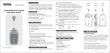
Combustible Gas Detector-Transmitter
E2648-LEL
User Manual

E2648-LEL Rev 10.05.2023
Table of contents
Acetylene 4
Butane 5
Hexane 6
Hydrogen 7
Methane 8
Octane 9
Propane 10
Specifications 11
Product description 13
Safety requirements 13
Operating conditions 14
Installation guidelines 14
Mounting dimensions 15
Sensor probe handling 16
Gas sensor replacement procedures 16
Electrical connections 17
Correct and incorrect cabling for 24 VAC 19
Operation 20
Maintenance 20
Calibration 20
Delivery set 21
Order code for E2648-LEL options 21
Configuring 22
Return to default settings 22
Modbus RTU Communication 23
2


E2648-LEL Rev 10.05.2023
Acetylene
A colorless flammable gas, lighter than air. Mixtures with air are explosive. It results from
the interaction of calcium carbide with water. In industrial production, acetylene is mainly
manufactured by the pyrolysis of light hydrocarbons.
Acetylene is widely used for welding and cutting of metals. The usage of acetylene as a
feedstock in the chemical industry declines due to cost and environmental considerations.
Synonyms/Trade Names: Ethine, Ethyne.
Chemical formula
HC≡CH
Molar weight
26
Relative gas density (to air)
0.90
Conversion
1 ppm = 1.06 mg/m3
Boiling point
-84 °C
Low explosive limit (LEL), % vol. in air
2.3* (2.5**)
Upper explosive limit (UEL), % vol. in air
100
Odor
Odorless or with a faint ethereal smell if pure. The
commercial-grade may have a garlic-like smell due to
impurities.
Hazards
Highly flammable.
Gas/air mixtures are explosive. Forms explosive
acetylide compounds with copper, mercury, silver &
brasses (containing more than 66% copper).
Asphyxiant. Non-toxic, but, when generated from calcium
carbide, it can contain toxic impurities such as traces of
phosphine and arsine.
Exposure limits
(NIOSH)
REL C
2662 mg/m3/2500 ppm
4

E2648-LEL Rev 10.05.2023
Butane
A colorless flammable gas that is heavier than air. The term “butane” is used for any of two
structural isomers (n-butane or iso-butane, with unbranched and branched-chain
respectively) or for their mixture. Occurs in light petroleum fractions.
Butane is used mainly as a fuel and as a feedstock in organic synthesis. It is applied also
as a propellant in aerosol sprays and may be used as an ozone-friendly refrigerant.
Mixtures of butane with propane and other hydrocarbons are referred to as LPG (liquefied
petroleum gas).
Chemical formula
n-butane
CH3CH2CH2CH3
iso-butane
CH3CH(CH3)CH3
Molar weight
58
Relative gas density (to air)
2.0
Conversion
1 ppm = 2.38 mg/m3
Boiling point
-0.56 °C
−11.7 °C
Low explosive limit (LEL), % vol. in air
1.4* (1.6**)
1.5* (1.8**)
Upper explosive limit (UEL), % vol. in air
8.4
9.6
Odor
Gasoline-like odor
Hazards
Highly flammable.
Inhalation of butane can cause euphoria, drowsiness,
narcosis, asphyxia, cardiac arrhythmia, fluctuations in
blood pressure, and temporary memory loss, when
abused directly from a highly pressurized container, and
can result in death from asphyxiation and ventricular
fibrillation.
Exposure limits
(NIOSH)
TWA
1900 mg/m3/800 ppm
Not established
5

E2648-LEL Rev 10.05.2023
Hexane
A colorless flammable gas that is heavier than air. Hexane is a constituent component of
gasoline. It is widely used in solvents as it is cheap, relatively safe and largely unreactive. It
is also used as an industrial cleaner and degreaser and is an ingredient in many consumer
products.
Chemical formula
C6H14
Molar weight
86.18
Relative gas density (to air)
2.97
Conversion
1 ppm = 3.52 mg/m3
Boiling point
68.7 °C
Low explosive limit (LEL), % vol. in air
1.0* (1.2**)
Upper explosive limit (UEL), % vol. in air
7.5
Odor
Petroleum-like odor
Hazards
Highly flammable.
Inhalation of hexane can cause irritation of respiratory
tract, cough, mild depression, cardiac arrhythmias.
Exposure limits
TWA
1800 mg/m3/500 ppm
6

E2648-LEL Rev 10.05.2023
Hydrogen
A colorless, odorless, flammable gas, that is much lighter than air. Mixtures with air are
explosive. Results from the interaction of acids, bases, and water with active metals and
from the electrolysis of aqueous solutions. In industrial production, the main source of
hydrogen is hydrocarbons.
Chemical formula
H2
Molar weight
2
Relative gas density (to air)
0.07
Conversion
1 ppm = 0.0818 mg/m3
Boiling point
−252.88 °C
Low explosive limit (LEL), % vol. in air
4.0
Upper explosive limit (UEL), % vol. in air
75
Odor
Odorless
Hazards
Flammable forms explosive mixtures with air.
Asphyxiant.
Exposure limits
not established
7

E2648-LEL Rev 10.05.2023
Methane
A colorless flammable gas, the main component of natural gas, marsh gases. Methane
results from bacterial decomposition of plant and animal matter (landfill gas).
Methane is widely used as a fuel and chemical feedstock.
Synonyms: Marsh Gas, Natural Gas, Carbon tetrahydride, Hydrogen carbide.
Chemical formula
CH4
Molar weight
16
Relative gas density (to air)
0.55
Conversion
1 ppm = 0.65 mg/m3
Boiling point
−161.49 °C
Low explosive limit (LEL), % vol. in air
4.4* (5.0**)
Upper explosive limit (UEL), % vol. in air
15
Odor
Odorless when pure. Methane used in the kitchens
contains an odorant
Hazards
Highly flammable, mixtures with air are explosive.
Asphyxiant.
Exposure limits
not established
8

E2648-LEL Rev 10.05.2023
Octane
A colorless flammable gas that is heavier than air. Octane is a component of gasoline
(petrol).
Chemical formula
C8H18
Molar weight
114.23
Relative gas density (to air)
3.86
Conversion
1 ppm = 4.67 mg/m3
Boiling point
125.6 °C
Low explosive limit (LEL), % vol. in air
1.0
Upper explosive limit (UEL), % vol. in air
6.5
Odor
Gasoline-like odor
Hazards
Highly flammable.
Inhalation of octane may cause irritation of respiratory
tract, depression, and pulmonary edema.
Exposure limits
(NIOSH)
TWA
350 mg/m3/75 ppm
9

E2648-LEL Rev 10.05.2023
Propane
A colorless flammable gas that is heavier than air. it occurs in light petroleum fractions.
Propane is used mainly as a fuel and as a feedstock in organic synthesis. It is applied also
as a propellant in aerosol sprays and may be used as an ozone-friendly refrigerant.
Mixtures of propane with butane and other hydrocarbons are referred to as LPG (liquefied
petroleum gas).
Chemical formula
CH8CH2CH8
Molar weight
44
Relative gas density (to air)
1.55
Conversion
1 ppm =1.80 mg/m3
Boiling point
−42 °C
Low explosive limit (LEL), % vol. in air
1.7* (2.1**)
Upper explosive limit (UEL), % vol. in air
9.5
Odor
Odorless when pure. Commercially available propane for
fuel purposes may contain odorant (“gas smell”).
Hazards
Highly flammable, mixtures with air are explosive.
Asphyxiant. May cause dizziness, confusion, excitation
when inhaled.
Exposure limits
(NIOSH)
TWA
1800 mg/m3/1000 ppm
IDLH
2100 ppm [10%LEL]
Conversion of ppm to mg/m3is calculated for 25°C and 1 atm.
* according to new EU standards ('stirred' concentration of gas)
** according to US standard (‘still gas’ method)
10

E2648-LEL Rev 10.05.2023
Specifications
Detected gases
Acetylene, butane, hexane, hydrogen, methane, octane, propane
Sampling method
Diffusion
Sensor type
Metal oxide semiconductor
Catalytic (pellistor)*
*not suitable for acetylene
Typical detection range
0...100% LEL
0...100% LEL
Resolution / digital unit
0.1% LEL
1% LEL
Response time T90
ca. 60 s
≤10 s
Sensor lifetime
> 5 years
> 3 years
Calibration interval
12 months
6 months
Operating conditions
-40...+70 °C
-10...+50°C
<95% RH non-condensing, 0,9...1,1 atm
Explosion-safe areas
Normal ambient oxygen level
Avoid exposure to corrosive gases or silicon-containing products
Signal update
Every 1 second
Load resistance
RL< (Us - 2 V) / 22 mA for 4-20 mA
RL> 250 kOhm for 0-10 V mode
Digital interface
RS485, Modbus RTU protocol
No galvanic isolation
Cable connections
Screwless spring-loaded terminal
Power supply
12...36 VDC (default),
24 VAC or 230 VAC as options
Power consumption
< 2 VA
Analog outputs
2 × 4-20 mA / 0-10 V, user settable
Outputs assignment
OUT1 gas; OUT2 gas
Output scale width
> 10 × resolution
Recommended: 20-100% of the detection range
Enclosure
Die-cast aluminium, wall mount, protection class IP66
Dimensions
H120 × W125 × D57 mm
11

E2648-LEL Rev 10.05.2023
CE marking
According to 2014/30/EU and 2014/35/EU, EN 50491-4-1:2012
EN 61000-6-3:2020, EN 61326-1:2013(EMC, emissions)
EN 61000-6-1:2019, EN 61000-6-2:2019(EMC, Immunity)
EN 60079-29-1:2016, EN 60079-29-2:2015 and EN 60079-29-3:2014
Relay option
Output relays
2 × SPST relays (closing contact),
250 VAC / 30 VDC, 5 A max
Default alarm setpoints
RE1 (LOW): set 20% LEL; release 16% LEL
RE2 (HIGH): set 50% LEL; release 40% LEL
Other options
Remote probe
Protection IP65, default cable length 3.0 m;
max height 80 mm, max diameter 65 mm
12

E2648-LEL Rev 10.05.2023
Product description
E2648 series heavy duty detectors-transmitters belong to the PluraSens® family of
multifunctional measurement instruments. The instruments utilize gas sensors of various
types with excellent repeatability, stability, and long lifetime. Due to its IP66 enclosure of
die-cast aluminum, the device may be used under harsh conditions.
E2648 series provides two independent analog outputs OUT1 and OUT2, user-selectable to
4-20 mA or 0-10 V, proportional to gas concentrations. RS485 Modbus RTU digital
communication interface allows easy instrument configuration and integration into various
automation systems.
The following features are available as an option:
●Two relays RE1 and RE2 with closing contacts. Relay outputs can be used to
switch alarm sirens, ventilation fans, shut-off valves, or other actuators,
●24 VAC or 230 VAC as options for power supply module,
●Remote probe.
The version of your detector is marked on the package. If the symbol is marked on the
equipment, consult the documentation for further information.
Safety requirements
Misuse will impair the protection of the product. Always adhere to the safety provisions
applicable in the country of use.
Do not perform any maintenance operation with the power on. Do not let water or foreign
objects inside the device.
Removal of the PCB from the enclosure voids the warranty. Do not touch the electronic
components directly, as they are sensitive to static electricity.
Connection diagrams can be found in the electrical connections section. The device might
not perform correctly or be damaged if the wrong power supply is connected.
External circuits connected to the equipment should have sufficient insulation rating
according to the environmental conditions and equipment power.
A disconnecting device that is marked as such and easily accessible should be included in
the installation of this product.
13

E2648-LEL Rev 10.05.2023
Operating conditions
The device should be used both in a non-hazardous area and in a basic electromagnetic
environment, where the latter is defined in EN 61326-1. Avoid strong mechanical shock and
vibrations. Avoid corrosive atmosphere and areas highly contaminated with dust, oil mist,
etc. Keep the instrument away from direct sunlight. A sudden temperature or humidity
change might affect the sensitivity of the sensor.
Installation guidelines
Before proceeding with the installation it is mandatory to read the Safety requirements
section and make sure to comply with all listed instructions. Installation standards EN
60079-29-2 and EN 45544-4 are also recommended for further instructions and related
information about the installation. During the installation of the transmitter the following
points must be considered:
●Application (the instrument is intended for leakage control.)
●Properties of the space under investigation (room geometry, direction, and
velocity of airflows, etc.),
●For gases lighter than air (hydrogen, methane, and acetylene) install the sensor
higher than the potential leakage/generation source or near the ceiling. Propane,
hexane, octane and butane are heavier than air and tend to sink. It is
recommended to place the sensor lower than potential leakage or generation
source.
●The device should be accessible for maintenance and repair.
The aforementioned conditions above will affect the coverage area of the device. however,
the coverage area for a transmitter is usually between 2.5 to 5 meters radius.
For early leakage detection install the sensor as close as possible to the potential leakage
sources (flanges, valves, pressure reducers, pumps, etc.), taking into consideration other
points listed above.
Do not locate the detector close to ventilation openings and strong air currents. Avoid the
areas without air circulation (corners, niches) as well.
For general area monitoring without definite leakage sources, the detectors should be
distributed evenly in the room.
For personal safety control, the detectors are installed in the breathing zone (at the height
of the head of people or animals). The recommended sensor position is vertical, pointing
downwards.
14

E2648-LEL Rev 10.05.2023
Unscrew four lid screws and detach the lid from the transmitter. Attach the device to a wall
with screws passing through mounting holes. The device is fixed on the wall using two
holes located outside the sealed area of the device.
Mounting dimensions
Front view
Bottom view
15

E2648-LEL Rev 10.05.2023
Sensor probe handling
The E2648 series devices are available with a remote probe. The remote probe is
connected to the main unit with a shielded cable. The default remote probe cable length is
3 m.
A) Wall mount remote probe with fixing clamp (default version),
B) Remote probe with rubber flange and three self-tapping screws (on request)
The sensor probes of all types are equipped with a hydrophobic microporous PTFE filter to
protect the sensor from dust, dirt, and water drops. The filter should be replaced if it gets
strongly contaminated. To replace the PTFE filter, unscrew the sensor head cap and
remove the old filter. Place a new filter into the cap and tighten it again.
NOTE! Never stab or press the filter near its center where the sensor is located since this
may damage the sensor. Do not remove the filter as it may cause the device to show
incorrect values and/or break the sensor.
The recommended orientation of the sensor probe is vertical with the sensor tip pointing
downwards. This prevents the possible accumulation of condensed water on the sensor
protection filter.
Gas sensor replacement procedures
1. Remove the sensor head cap from the device (or the remote probe),
2. Remove the PTFE filter (if it is not removed within the cap),
3. Remove the O-ring rubber,
4. Detach the pellistor (catalytic) sensor from the device,
5. Insert the new pellistor (catalytic) sensor inside,
6. Put back the O-ring rubber, PTFE filter, and the head cap, respectively.
NOTE! Metal oxide semiconductor sensors are not replaceable!
16

E2648-LEL Rev 10.05.2023
Electrical connections
Unscrew four lid screws and detach the lid from the device. Use the M16 cable gland to let
in cables of the power supply and of the external devices. Attach the power cable to the
device without turning it on. Using the connection diagram below, connect the analog
outputs and digital interface terminals to the relevant devices according to your tasks.
Version with PSU and relays Version with PSU and without relays
Version without PSU and with relays Version without PSU and relays
17

E2648-LEL Rev 10.05.2023
Jumpers
J1
OUT1 type (open: 4-20 mA; closed 0-10 V)
J2
OUT2 type (open: 4-20 mA; closed 0-10 V)
X6
Reset Modbus network parameters to default
X4 terminals
OUT1
4-20 mA / 0-10 V output
OUT2
4-20 mA / 0-10 V output
0V
0 V / 24 VAC Neutral (optional)
A
RS485 A / Data +
B
RS485 B / Data -
+U
+24 VDC / 24 VAC Phase (optional)
X5 terminals (optional)
L
90…265 VAC Phase
N
90…265 VAC Neutral
RE1 NO
Relay 1, normally open terminal
RE1 COM
Relay 1, common terminal
RE2 NO
Relay 2, normally open terminal
RE2 COM
Relay 2, common terminal
The screwless quick connect spring terminals on the E2648 series devices are suitable for
a wide range of wires with a cross-section of 0.2...1.5 mm2. We recommend striping the
wire end by 8...9 mm and using wire end sleeves.
To connect the wire, insert the wire end into the terminal hole. To disconnect, push the
spring-loaded terminal lever, pull the wire out, and release the lever.
Use a twisted-pair cable, e.g. LiYY TP 2×2×0.5 mm2or CAT 5, to connect the device to the
RS485 network. A and B on the device represent DATA+ and DATA- respectively, polarity
must be respected when connecting to an external RS485 network.
Both analog outputs can be independently changed between 4-20 mA and 0-10 V type
using jumpers J1 (OUT1) and J2 (OUT2). By closing pins on a specific jumper the related
output is 0-10 V, with an open jumper the output is 4-20 mA. Power restart is required after
changing the position of the jumpers.
18

E2648-LEL Rev 10.05.2023
NOTE! The outputs are not galvanically isolated from the external power supply and share
a common 0V. Allowed load resistance limits are stated in the Specifications table. To
power the instrument from an external power source, connect terminals 0V and +U to the
source. If the integrated mains power supply module is used, connect terminals L and N to
the mains.
NOTE! Actuator short-circuits should be avoided, to protect the instrument relays using
external fuses or safety switches.
Correct and incorrect cabling for 24 VAC
19

E2648-LEL Rev 10.05.2023
Operation
Turn on the power. The instrument warm-up time for both types of sensors takes about 5
minutes after switching on and final sensor stabilization time to maximum accuracy takes
about 1 hour. The operating status is indicated by the LED on the PCB of the device. The
control LED (red) response to different processes is presented in the following table:
Mode
LED mode
During calibration mode or sensor heating
period (if activated)
0.5 Hz (50% on, 50% off)
Relay 1 turned on
Blinking 1 Hz (50% on, 50% off)
Relay 2 turned on
Blinking 2 Hz (50% on, 50% off)
During the Modbus communication cycle
Short on-off pulses
Normal operating/measurement
Continuously on or off
Make sure that the transmitter is properly mounted, the external devices connected, the
power LED (green) on, and the control LED (red) is constantly lit. Make certain that the
cable glands are properly tightened to ensure the conformity to IP66 protection class.
Place the lid back and fix it with the screws. The device is ready to use.
Maintenance
Do not perform any maintenance operation with the power on.
Clean the device with a soft damp cloth. Do not use any abrasive cleaning agents. Do not
immerse the device in water or any cleaning media.
Calibration
E2648-LEL devices have been calibrated by the Manufacturer with standard gas mixtures
before delivery. Provided that the sensor is used under moderate conditions, the
recommended recalibration interval for the metal oxide sensor is 12 months. Catalytic
sensors are more sensitive to the environment and require field recalibration every 6
months. Please contact your dealer for more information.
20
/