Page is loading ...


Table of contents
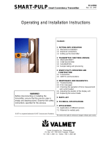
Caution / Warning
Recycling and disposal
Introduction 71.
General............................................................71.1.
Structure 92.
MCA-F..............................................................92.1.
MCA-FT............................................................92.2.
Sensor Electronics ........................................122.3.
Transmitter Central Unit (TCU) .....................122.4.
Installation 133.
General principles..........................................133.1.
Choosing the installation site.........................133.2.
Sensor dimensions.........................................173.3.
Mounting dimensions.....................................193.4.
MCA-F process coupling................................193.5.
Transmitter Central Unit (TCU) and shield.....203.6.
Electrical Connections ...................................203.7.
Valmet MCA-F Sensor Deflector Plate Installation
Guide..............................................................22
3.8.
Setting Up 234.
Mechanical Inspection....................................234.1.
Installation......................................................234.2.
Cabling Inspection..........................................234.3.
Electrical Inspection.......................................234.4.
Configuration and Calibration........................234.5.
User Interface and Operation 255.
Transmitter Central Unit.................................255.1.
Operations Menu............................................265.2.
Configuration 276.
Configuration menu........................................276.1.
Choosing and scaling the output signal.........276.2.
User Settings..................................................276.3.
Device information ........................................286.4.
Setting the date and time...............................286.5.
Address..........................................................286.6.
Calibration 297.
Sample Taking................................................297.1.
Entering Laboratory Results..........................307.2.
Offset Correction............................................307.3.
Fillers..............................................................307.4.
Calibration and sample history ......................317.5.
Diagnostics 338.
Error Table......................................................338.1.
Diagnostics Values.........................................338.2.
Diagnostics Limits..........................................338.3.
Special Functions 359.
Chemical compensation.................................359.1.
Sensitivity Correction.....................................389.2.
Recipes..........................................................399.3.
Troubleshooting 4110.
Troubleshooting.............................................4110.1.
Process Conditions........................................4110.2.
Self-diagnostics error messages....................4310.3.
Replacing Components 4511.
Sensor Electronics.........................................4511.1.
Antenna cables, Fork Sensor.........................4611.2.
Antenna Cables, FT Sensor...........................4811.3.
Antennas, Fork Sensor..................................4911.4.
Antennas, FT Sensor.....................................4911.5.
TCU ...............................................................5011.6.
Installing Vortex Cooler..................................5011.7.
HART® User Interface 5112.
About the interface.........................................5112.1.
Measurement.................................................5212.2.
Configure........................................................5212.3.
Calibrate.........................................................5312.4.
Diagnostics.....................................................5712.5.
Technical Specifications
Service kits & Spare parts
CE Declaration of conformity
Installation & Owner’s manual OUL00298 V2.3 EN
3
Valmet Mircowave Consistency Transmitter


Caution / Warning
During installation, maintenance and service operations, remember that
the sample line may contain hot sample or water – be careful!
Always check that the incoming voltage & frequency are correct before
making any electric connections. Wrong connection may damage the
equipment! The applicable electrical safety regulations must be closely
followed in all installation work!
Before any welding works in the vicinity of the devices, make sure that
operating voltage is not connected!
Installation & Owner’s manual OUL00298 V2.3 EN
5
Valmet Mircowave Consistency Transmitter

Recycling and disposal
When sorted by material, nearly all parts of the device can be recycled.
A materials list is delivered with the device. Upon request, the manufac-
turer will provide more detailed instructions for recycling and disposal.
Used devices may also be returned to the manufacturer for recycling and
disposal against a separate fee.
Installation & Owner’s manual OUL00298 V2.3 EN
6
Valmet Mircowave Consistency Transmitter

1. Introduction
1.1. General
Valmet Mircowave Consistency Transmitter (Valmet
MCA) functions based on the measurement of mi-
crowave propagation time.
Microwaves are electromagnetic radiation; the flying
time depends on the media's dielectric constant. Flying
time is calculated as follows:
c = speed of light in a vacuum
er = media's dielectric constant
In water microwaves advance at a much slower speed
that in wood fiber. Therefore, consistency can be calcu-
lated based on the time it takes the microwaves to
move through the measured mass.
The advantages of this measurement procedure are
pulp type-independence, insensitivity to flow speed,
and single-point calibration.
There are two different models of Valmet MCA sensors:
- Valmet MCA-F Fork sensor (figure 2).
- Valmet MCA-FT Flow-through sensors (figure 3).
Valmet MCA also includes a user interface known
as Transmitter Central Unit (TCU) (figure 1).
Fig. 1. Transmitter Central Unit (TCU).
Fig. 2. Valmet MCA-F.
Fig. 3. MCA-FT.
Installation & Owner’s manual OUL00298 V2.3 EN
7
Valmet Mircowave Consistency Transmitter


2. Structure
Valmet MCA comprises the sensor unit and a user in-
terface called Transmitter Central Unit. There are two
sensor models: MCA-F Fork Sensor and MCA-FT Flow-
Through Sensor, which come in six different sizes
ranging from FT-50 to FT-300. The appropriate model
is selected according to the diamater of the process
pipe.
2.1. MCA-F
In the fork-type MCA-F sensor, the microwave antennas
are mounted on the sensor body, which is installed via
a coupling into the process pipe. On the end of the
sensor there is a probe antenna and on the base there
is a flushmounted antenna. In addition, on the end of
the sensor body there is a Pt-100 thermoelement. The
antenna cables and the Pt-100 sensor cables run
through the inside of the sensor to the sensor electron-
ics.Figure 3 shows the sensor's construction drawing.
The material of the wetted metal parts is AISI316L,
with options of titanium or hastelloy. The antenna ma-
terial is polished ceramic.
1
23
4
Fig. 1. Valmet MCA-F: 1. Pt-100 Thermoelement, 2.
Microwave Antennas, 3. Sensor Electronics, 4. Sensor
Cable Connector.
2.2. MCA-FT
The body of the Flow-Through sensor is a pipe, which,
when installed, replaces an identical length of process
pipe. Flush-mounted antennas are installed on opposite
sides of the sensor body, so measurement takes place
through the pipe. The sensor electronics casings is in-
stalled on the sensor body by means of a connecting
pipe. The Pt-100 sensor, which measures process
temperature, is installed inside the connecting pipe.
The antenna cables, which are protected within casing,
run to the base plate of the electronics casing on the
outside of the connecting pipe. Figure 4 shows the
sensor's construction drawing.
The material of the wetted sensor and antenna
bodies is AISI 316/316L. The antenna material is pol-
ished ceramic.
1
2
3
4
5
Fig. 2. Valmet MCA-FT: 1. Sensor Electronics, 2.
Sensor Cable Connector, 3. Antenna Cable, 4. Pt-100
Thermoelement, 5. Microwave Antennas.
Installation & Owner’s manual OUL00298 V2.3 EN
9
Valmet Mircowave Consistency Transmitter

1
2
3
4
5
6
7
8
9
10
Fig. 3. Valmet MCA-F construction drawing: 1. Microwave Antenna, 2. Sensor Head, 3. Pt-100 Thermoelement,
4. Antenna Cables, 5. Sensor Body, 6. Antenna Sealing, 7. Fixing Clamp, 8. Base Plate Assembly, 9. Sensor
Electronics, 10. Sensor Cover.
Installation & Owner’s manual OUL00298 V2.3 EN
10
Valmet Mircowave Consistency Transmitter

1
2
3
4
5
6
7
8
9
10
Fig. 4. Valmet MCA-FT construction drawing: 1. Sensor Cover, 2. Sensor Electronics, 3. Base Plate Assembly,
4. Pt-100 Thermoelement, 5. Sensor Body, 6. Antenna Sealing, 7. Microwave Antenna, 8. Antenna Flange, 9.
Antenna Cable, 10. Antenna Cover.
Installation & Owner’s manual OUL00298 V2.3 EN
11
Valmet Mircowave Consistency Transmitter

2.3. Sensor Electronics
Sensor electronics is the same for both Fork and
Flowthrough sensors. Refer to figure 6. The sensor
electronics card is installed between the round cover
and base. The electronics includes the microwave
transmitter and receiver as well as control, measure-
ment and communication electronics.
On the bottom there are snap-on connectors, which
connect with antenna cable connectors in the base
plate when you press the electronics against the base
plate. The guide pins in the base plate help guide the
connectors into place. The Pt-100 connector and the
supply voltage / serial communication connector are
connected into the connectors located in the cover of
the sensor electronics.
2.4. Transmitter Central Unit (TCU)
TCU is Valmet MCA's user interface and calculator.
Perform operations using the number buttons and other
buttons and the four-line display. The TCU is delivered
attached to the shield, as shown in figure 5.
Connectors:
– For the sensor unit, sensor electronics supply
voltage and RS485 serial port connectors.
– For the current outputs (passive). From TCU Rev B,
2 current outputs.
– For HART communicator. (HART only in the current
output 1.).
– For RS232 connection to a PC (for maintenance
purposes).
– For network voltage.
Fig. 5. Transmitter Central unit.
1
2
3
4
5
Fig. 6. Sensor Electronics: 1. Power Cable Connector, 2. Fixing Screw, 3. Pt-100 Connector, 4. Guide hole, 5.
Antenna Cable Connectors.
Installation & Owner’s manual OUL00298 V2.3 EN
12
Valmet Mircowave Consistency Transmitter

3. Installation
3.1. General principles
The sensor model is selected according to the size of
the pipe. Flow-through models are FT50/2", FT100/4",
FT150/6", FT200/8", FT250/10", and FT300/12".
Flowthrough models can be installed on the following
pipe flanges:
– DIN PN10
– DIN PN16
– ANSI Class 150
– JIS 10K
In laboratory analysis of measurement results it is
important to use a proper sampler (e.g. NOVE). Install
it according to MCA installation instructions.
NOTE! Before installing the process coupling or sensor,
check that the process pipe is empty and unpressurized
and that installation is safe.
3.2. Choosing the installation site
The fork-type Valmet MCA-F sensor can be installed
on pipes with a diameter of 150 mm (6") or larger. In
choosing an installation position, note the following:
– It is not recommended to install Valmet MCA-F
sensor in a place where the pulp may contain strings,
etc., that may get wrapped around the sensor. If
necessary, use a separate deflector plate.
– Do not install the sensor on the pump's suction side
or in the mixing tank.
– After the sensor there should be a straight section
of pipe, length at least 2 times the pipe diameter,
before a change in pipe profile.
– Adjacent to Valmet MCA-F sensor or one meter be-
fore it there must not be objects inserted into the
pipe.
– Reserve enough space for the sensor casing. For
the Valmet MCA-F, reserve also space required for
sensor installation.
– The TCU must be installed within 10 meters of the
sensor. The sensor cable is 10m long. You also have
the option of purchasing a 10m extension cable.
In addition, you must note the following specifications:
– Process temperature under 100 °C.
– pH range 2.5...11.5.
– Conductivity according to sensor specifications.
– Recommended process pressure is 1.5 - 25 bar
(Fork sensor) / 16 bar (FT sensor) to eliminate the
effect of air bubbles.
– Sensor pressure tolerance:
• Fork sensor PN25
• FT sensor PN16
Installation checklist:
– Check that the mounting location and position are
in accordance with the installation instructions.
– Check that the flow arrow on the sensor casing is
pointing in the direction of flow.
– Protect the sensor and the TCU from direct heat
sources and sunlight.
– Valmet MCA-F: Before operating the sensor, check
that the process coupling's mounting clamp is se-
curely tightened.
–Valmet MCA-FT: Before operating the sensor, check
that the sealing between the MCA flanges and pro-
cess flanges are properly installed and that the
mounting nuts are tightened.
Sensor installation to a vertical and horizontal
pipeline is illustrated in Fig. 1 - 5.
Installation & Owner’s manual OUL00298 V2.3 EN
13
Valmet Mircowave Consistency Transmitter

AB
D
1xD if
Cs>8%
Min2xD
D
1xD if
Cs>8%
Min2xD
Measuring line at a 90° angle
towards the pump axis. Measuring line parallel to
the previous horizontal pipe.
Fig. 1. Valmet MCA-F Installation on a vertical pipe: A. after a pump, B. after a horizontal pipe.
AB
D
D
Min2xD
1xD if
Cs>8%
Min2xD
1xD if
Cs>8%
If the section of horizontal pipe preceding the
sensor is >10xD, then the sensor is installed
with its electronics casing on side.
Fig. 2. Valmet MCA-F Installation on a horizontal pipe: A. after a vertical pipe, B. after a bend in the pipe.
Installation & Owner’s manual OUL00298 V2.3 EN
14
Valmet Mircowave Consistency Transmitter

D
D
AB
1xD if
Cs>8%
Min2xD
1xD if
Cs>8%
Min2xD
Measuring line at a 90° angle
towards the pump axis. Measuring line parallel to
the previous horizontal pipe.
Fig. 3. Valmet MCA-FT Installation on a vertical pipe: A. after a pump, B. after a horizontal pipe.
D
ABD
Min2xD
1xD if
Cs>8%
Min2xD
1xD if
Cs>8%
If the section of horizontal pipe
preceding the sensor is >10xD, then
the sensor is installed with its electronics
casing on top.
Fig. 4. Valmet MCA-FT Installation on a horizontal pipe: A. after a bend in the pipe, B. after a vertical pipe.
Installation & Owner’s manual OUL00298 V2.3 EN
15
Valmet Mircowave Consistency Transmitter


3.3. Sensor dimensions
223 (8.7”)
275 (10.8”)
156 (6.1”)
20 (0.8”)
210 (8.2”)
9
(3.5”)
0
Fig. 7. Dimensions, Valmet MCA-F.
223 (878”) 210 (8.2”)
226 (8.8”)
100 (3.9”)
164 (6.5”)
1
(4”)
02
54
(2.1”)
.4
MCA FT50/2"
223 (8.7”)
159
(6.2)
191 (7.5”)
254 (10”)
210 (8.2”)
100 (3.9”)
MCA FT100/4”
1
(4.1”)
05
Fig. 8. Dimensions, Valmet MCA-FT50 and -FT100.
Installation & Owner’s manual OUL00298 V2.3 EN
17
Valmet Mircowave Consistency Transmitter

223 (8.7”)
223 (8.7”)
215
(8.5”)
280 (11”)
270
(10.6”)
100
304 (12”)
210 (8.2”)
210 (8.2”)
225 (8.8”)
100 (3.9”)
100 (3.9”)
MCA FT150/6" MCA FT200/8"
155
(6.1”)
203
(8”)
Fig. 9. Dimensions, Valmet MCA-FT150 and -FT200.
MCA FT250/10" MCA FT300/12"
223 (8.7”)
320
(12.5”)
120
(4.7”)
330 (12.9”)
210 (8.2”)
255
(8.8”)
223 (8.7”)
(12”)
120
370
(14.5”)
355 (14”)
(4.7”)
210 (8.2”)
305
Fig. 10. Dimensions, Valmet MCA-FT250 and -FT300.
Installation & Owner’s manual OUL00298 V2.3 EN
18
Valmet Mircowave Consistency Transmitter

3.4. Mounting dimensions
Valmet MCA-F
The fork-type Valmet MCA-F sensor is installed in a
process coupling welded onto the side of the process
pipe in such a way that the probe antenna is directed
against the direction of the flow (Fig. 11). The sensor
is loosely tightened into place with mounting clamps
and then approximately aligned with the pipe based on
the position of the electronics casing. After aligning,
tighten the mounting clamps to their final tightness. The
sticker on the electronics casing indicates the installa-
tion direction in relation to the direction of flow.
NOTE: The probe antenna on the end of the sensor is
ceramic, so avoid denting it.
Valmet MCA-FT
When installed, the flow-through sensor replaces the
corresponding length of process pipe (Fig. 12). The
sticker on the electronics casing indicates the installa-
tion direction in relation to the direction of flow. The
sensors do not include flanges, but rather they are
tightened with stud bolts between flanges mounted on
the process pipe.
6.14"
156
4.69"
119
8.27"
210
min. 500 mm (20")
FLOW
Fig. 11. Valmet MCA-F Mounting dimensions.
L
MIN. 500 mm (20")
Fig. 12. Valmet MCA-FT Mounting dimensions.
3.5. MCA-F process coupling
Installing the process coupling:
– Make a 71 mm hole in the flow pipe in line with the
sensor.
– If necessary, shape the process coupling (curvature
radius of installation surface) to the shape of the
pipe.
– Align the process coupling with the hole and weld
and weld four adhesion welds around the seam.
– Weld a continuous weld around the seam.
When process pressure is over 10 bar and/or there
is exceptionally strong vibration, the mounting of the
process coupling should be reinforced with a reinforcing
ring. The area where the deflectors are inserted should
also be reinforced in the same way.
In Fig. 14:
D = inside diameter of pipe
s = wall thickness of pipe
lo = width of reinforcing ring
h = thickness of reinforcing ring
Note that if the pipe wall is thicker than what is indic-
ated in the table, the thickness of the reinforcing ring
can be reduced correspondingly.
4 weld
FLOW
22
90
79
71
90°
± 0.5
Fig. 13. Installation of process coupling.
h
Io
s
min.
6mm
D s p max. T max. h lo
mm mm bar °C mm mm
250 4 25 100 5 32
400 6 25 100 5 50
500 7 25 100 6 60
Fig. 14. Reinforcing the process coupling.
Installation & Owner’s manual OUL00298 V2.3 EN
19
Valmet Mircowave Consistency Transmitter

3.6. Transmitter Central Unit (TCU) and shield
The TCU is delivered attached to the shield. The shield
is attached to the wall with three mounting screws in a
place that is easily accessed.
When selecting a place for the TCU, remember that
the sensor cable is 10 m long. Figure 15 shows shield
mounting dimensions.
3.7. Electrical Connections
NOTE: When connecting the power supply cables, check
that the cables are de-energized. Perform and check all
connections before you connect the power supply to the
cables.
NOTE: If the TCU has been switched off for a long time,
it may take a few minutes for text to appear on the dis-
play. This is due to the charging of the device's internal
back-up battery.
Sensor Cable
NOTE: In a normal delivery, the sensor cable is already
connected to the TCU.
1. Insert the end of the sensor cable that has no
connector into the TCU connector casing through
the inlet and connect it as shown in Figure 17. The
protective shields are connected as follows:
- Twisted pair lines' intertwined protective shields
(cable 3) are connected to adaptor GND together
with cable 2.
- The sensor cable's protective shield (cable 5) is
connected to adaptor SC SHIELD (Sensor Cable
Shield).
2. Bring the sensor cable to the sensor unit and
connect its adaptor to the adaptor in the base plate
of the sensor electronics.
NOTE: Do not place the sensor cable on cable shelves
that contain cables of motors, pumps or other electrical
cables.
232 (9.13")
70 (2.76")
31 (1.22")
236 (9.29")
133 (5.24")
282 (11.10")
Fig. 15. TCU shield mounting dimensions.
Installation & Owner’s manual OUL00298 V2.3 EN
20
Valmet Mircowave Consistency Transmitter
/