
Elcold Frysere Hobro ApS
Løgstørvej 81 Hørby 9500 Hobro Denmark
Phone +45 9657 2222 Fax +45 9852 4685
Email [email protected] www.elcold.com
i.c. graphics cph

Low Temperature Freezers Model UNI/LT
User Instructions

User Instructions Low Temperature Freezers Model UNI/LT
2
USER INSTRUCTIONS
Congratulations on your new low temperature
freezer. We trust that it will serve you for many years
to come. In order to gain optimum benefit from
your freezer, please read the following instructions
thoroughly and act accordingly. The low-tempera-
ture freezers are used for freezing and long-term
storing of food products, medical preparations (
vaccines, blood plasm, ect.) and other biological
products.
1. Environmental protection and disposal.
The packaging is designed to protect the
appliance and its components during
transportation, and it is made of recyclable
materials.
• Please return the packaging to an
official collection point for recycling.
• Old appliances contain reusable
materials and should not be disposed
of together with household refuse.
• Remove the spring-action hinges from
the appliance, in order to prevent
children from being entrapped in the
appliance.
• Ensure that no part of the refrigeration
tubing is damaged as the refrigerant
in the appliance risks escaping to the
environment.
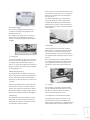
• Information about refrigerant type
and amount will be found on the type
plate on the rear of the appliance
(Fig. 1).
2. Safety instructions.
• In order to prevent injuries and or
damage to the appliance, it should
be unpacked and set up by min. two
people.
• If upon unpacking the appliance is
found damaged, do not connect to
the mains, but contact the supplier.
• Interference with or repair to the
appliance should only be carried out
by authorized personnel, in order to
avoid any injuries. (contact the sup-
plier for further information).
• Never put naked flames or other igni-
tion sources inside the appliance.
• Never touch the freezers interior or
products in the freezer when the
freezer is operating. Use gloves or alike
in order to avoid injuries (frost-bite).
• Keep the key to the appliance away
from the appliance and out of the
reach of children.
3. Connection to the mains.
• For safety reasons the appliance must
be earthed. If you are in any doubt,
please contact an authorized electri
cian.
• The appliance should be left for 5
hours before it is connected to the
mains. If the appliance is connected
before that, there is a risk of damaging
the compressor.
• If for any reason the appliance is
disconnected from the mains, please
wait 10 minutes before re-connecting.
The electronic starting device needs
this time to cool down, before a safe
re-start can be made.
4. Before use.
• Before use, the interior of the appli-
ance should be cleaned with a mild
soap solution, and wiped off with a dry
clean cloth. Never use any kind of
solvent or other chemicals.
5. Setting up the freezer.
The freezer should not be placed where it
might be splashed with water, in extreme
high humidity or in direct sunlight. Any of
these factors may lead to a reduction in
performance and shorten the life span of
the components. The freezer should be
placed on a horizontal level, and should
not be placed close to a heating appliance
or heating tubes. Allow a minimum of 50mm
(2”) clearance on the side and the back.
The side with the ventilation grill should have
a clearance of at least 100 mm (4”) in order
to allow the heat from the compressor
motor to dissipate. Underneath the appli-
ance there should be a gap of 15 mm ap-
prox. (1⁄2”). On a soft surface, e.g. carpet,
it may be necessary to ensure the correct
distance by means of spacers.
GB

User Instructions Low Temperature Freezers Model UNI/LT
6. Electrical supply.
The electrical supply should always be in
accordance with the rating plate on the
back of the freezer.
The supply must always be in accordance
with the law and regulations regarding
electrical safety, if any doubts contact your
supplier.
7. Starting Up.
In case the compressor does not start when
the freezer has been plugged in, the electri-
cal supply may not be in order. Check if
there is an electricity supply to the plug or if
the fuse is blown. If not please go to trouble
shooting page 6. 18.
8.Operating the freezer
The empty freezer should be switched on
for at least 5-6 hours prior to loading of the
freezer. The freezer should not be loaded
above the inside walls which is also the load
line limit.
Please note: After the lid has been opened,
there will be a vacuum created inside the
freezer due to the low temperatures. Wait a
few minutes before trying to reopen the lid
otherwise the handle could be damaged.
9.Defrosting.
In order for the freezer to work to its maxi-
mum efficiency the cabinet should be de-
frosted when a approx. 2mm thick ice layer
has formed inside the cabinet.
The ice layer is easily removed with a plastic
or wooden scraper. Never use a sharp metal
object which might will cause damage to
the inner liner.
The defrosting frequency is determined
mainly by two factors the usage pattern
(number of lid openings) and the relative
humidity. Excess water can be drained out
by using the drain water outlet on the front
of the freezer.
10.Cleaning.
Cleaning should be done when needed.
When used in a dirty environment it might
be necessary to remove the compressor
compartment grill, and clean the compres-
sor compartment eventually with a vacuum
cleaner.
If the cleaning process is neglected there
is a risk that the performance of the freezer
will be effected, and even damage to the
compressor could occur due to overheat-
ing.
11. Storage.
If the freezer is stored for a period of time,
the lid should be kept open for free circula-
tion of air inside the cabinet in order to
avoid corrosion of the inner liner.
12. Temperature control UNI/LT- freezers.
The temperature inside the freezer is con-
trolled by the electronic controller in the
front grill. The controller has a digital readout
of the temperature inside the cabinet. and
3
Fig. 1

User Instructions Low Temperature Freezers Model UNI/LT
the option of changing the temperature
inside the cabinet.
13. External voltage and temperature alarm.
Optionally the freezer can be equipped with
a battery operated alarm box with connec-
tions for external alarm for voltage failure
and temperature alarm. The battery should
be exchanged every two years.
Please note! When commissioning the
freezer, the battery must be turned into its
correct position. More details on page 17.
14.Dixell controller.
15. Functions.
How to see the set point:
1.Press and immediately release the SET key,
the display will now show the set point value.
2.Press and immediately release the SET key
or wait for 5 seconds to display the probe
value again.
How to lock and unlock the keyboard
1.Press the up and down keys simultaneously
for more than 3.seconds.
How to change the set point
1.Press the SET key for more than 3.seconds
to change the set point value.
2.The set point value will be displayed and
the LED starts flashing.
3.To change the set point value, push the up
or down arrow.
4. To memorise the new setting press the SET
key again or wait 15 seconds for the control-
ler to return to normal display of the probe
temperature.
16. Setting the controllers offset value
The UNI/LT freezer is designed for long time
and safe storage of sensitive products.
In some situations the UNI/LT freezer is also
used for other applications like in laborato-
ries for different low temperature test.
Depending on the actual situation it might
be necessary to change the controllers off-
set value in order to get a correspondence
between the reading on the display and the
actual temperature inside the cabinet.
The factory setting is an offset of 0 dgr:C.
The offset can be adjusted in the following
way.
Unlock the keyboard.
Enter the programming mode by pressing
the SET and arrow down keys for 3 seconds.
Select the parameter “Ot” by pressing arrow
up or down key.
Press the SET key to display its value.
Use arrow up or down to change its value.
The offset can be adjusted to +/- 12 dgr .C
Press SET to store the new value.
Press SET + arrow up or wait 15 seconds
without pressing any key. The new value will
now be stored.
For more detailed information about
programming the Dixell controllers please
consult the attached manuals.
17. Trouble shooting.
The appliance is not operating. Please
check:
Is the electrical plug connected to the
mains (wall socket)? Has the fuse blown?
The temperature inside the appliance is too
high. Please check:
Is the Dixell controller set to the correct
temperature?
Has an excess amount of ice formed inside
the appliance?
The appliance is operating continuously.
Please check:
Is the ambient temperature very high?
Has the appliance recently been loaded
with a large amount of warm products?
If you have checked the above points and the appli-
ance is still not working as expected, please contact
your local dealer for further advice.
4

User Instructions Low Temperature Freezers Model UNI/LT
5
INSTALLING AND OPERATING INSTRUCTIONS
GENERAL WARNING
Please read before using this
manual
• This manual is part of the product and
should be kept near the instrument for
easy and quick reference.
• The instrument shall not be used for
purposes different from those de
scribed hereunder. It cannot be used
as a safety device.
• Check the application limits before
proceeding.
Safety Precautions
• Check the supply voltage is correct
before connecting the instrument.
• Do not expose to water or moisture:
use the controller only within the
operating limits avoiding sudden
temperature changes with high at-
mospheric humidity to prevent forma-
tion of condensation
• Warning: disconnect all electrical con-
nections before any kind of mainte-
nance
• Fit the probe where it is not accessible
by the End User. The instrument must
not be opened.
• In case of failure or faulty operation
send the instrument back to the dis-
tributor with a detailed description of
the fault.
• Consider the maximum current which
can be applied to each relay (see
Technical Data).
• Ensure that the wires for probes, loads
and the power supply are separated
and far enough from each other,
without crossing or intertwining.
• In case of applications in industrial
environments, the use of mains filters
(our mod. FT1) in parallel with
inductive loads could be useful.
GENERAL DESCRIPTION
Model XR30C, format 32 x 74 mm, is a digital
termostat with off cycle defrost designed for
refrigeration applications at normal temper-
ature. It provides two relay outputs, one for
the compressor, the other one can be used
for alarm signalling or as auxiliary output. The
probe input can be selected between PTC
or NTC. The instrument has a digital input, for
alarm signalling, for switching the auxiliary
output or for start a defrost cycle. The instru-
ment is fully configurable through special
parameters that can be easily programmed
through the keyboard.
CONTROLLER LOADS
COMPRESSOR
The regulation is performed according to
the temperature measured by the thermo-
stat probe with a positive differential from
the set point: if the temperature increases
and reaches set point plus differential the
compressor is started and then turned off
when the temperature reaches the set point
value again.
In case of fault in the thermostat probe the
start and stop of the compressor are timed
through parameters “COn” and “COF”.
DEFROST
Defrost is performed through a simple stop
of the compressor. Parameter “IdF” controls
the interval between defrost cycles, while its
length is controlled by parameter “MdF”.
Digital controller with off cycle
defrost
XR30C

User Instructions Low Temperature Freezers Model UNI/LT
6
FRONT PANEL COMMANDS
SET: To display target set point; in pro
gramming mode it selects a
parameter or confirm an opera
tion.
(DEF) To start a manual defrost
(UP) To see the last temperature
alarm happened; in program
ming mode it browses the para-
meter codes or increases the
displayed value.
(DOWN) To see the last temp-
erature alarm happened; hold
pressed it switches the auxiliary
output; in programming mode it
browses the parameter codes or
decreases the displayed value.
KEY COMBINATIONS:
+ To lock & unlock the keyboard.
SET + To enter in programming mode.
SET + To return to the room temperature
display.
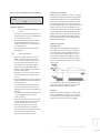
TEMPERATURE ALARM AND ITS DURATION
RECORDING (HACCP)
XR30C signals and records temperature
alarms, together with their duration and
max value reached. See drawing:
HOW TO SEE THE ALARM DURATION AND MAX
(MIN) TEMPERATURE
If the alarm LED is on, an alarm has taken
place.
To see the kind of alarm, the max (min)
reached temperature and alarm duration
do as follows:
1. Push the Up or Down key.
2. On the display the following mes
sage is shown::
“HAL” for high temperature alarm
(“LAL” fot the minimum allarm),
followed by the Maximum (mini-
mum) temperature.
Then the “tiM” (tiMe) message is
displayed, followed by the “Dura-
tion” in h.mm.
3. Then the instrument displays the
temperature once again.
NOTE1: if an alarm is still occurring the “tim”
shows the partial duration.
NOTE2: the alarm is recorded when the tem-
perature come back to normal values
HOW TO RESET A RECORDED ALARM OR ONE
THAT IS STILL OCCURRING
1. Hold the SET key pressed for more
than 3s, while the recorded alarm
is displayed. (the rSt message will
be displayed)
2. To confirm the operation, the “rSt”
message starts blinking and the
normal temperature will be dis
played.
MAIN FUNCTIONS
HOW TO SEE THE SETPOINT
1. Push and immediately release
the SET key: the display will show
the Set point value;
2. Push and immediately release
the SET key or wait for 5 sec-
onds to display the probe value
again.
HOW TO CHANGE THE SETPOINT
1. Push the SET key for more than 2
seconds to change the Set point
value;
2. The value of the set point will be
SET

User Instructions Low Temperature Freezers Model UNI/LT
displayed and the LED starts
blinking;
3. To change the Set value push the
o or n arrows within 10s.
4. To memorise the new set point
value push the SET key again or
wait 10s.
HOW TO START A MANUAL DEFROST
Push the DEF key for more than
2 seconds and a manual defrost
will start.
HOW TO SWITCH ON OR OFF THE SECOND
RELAY(OAC= LHt)
Hold pressed the n key for some
seconds, till the AUX LED is turned
ON or OFF
HOW TO CHANGE A PARAMETER VALUE
To change the parameter’s value operate
as follows:
1. Enter the Programming mode
by pressing the Set and
DOWN key for 3s ( and
start blinking).
2. Select the required parameter.
3. Press the “SET” key to display its value
(now only the LED is blinking).
4. Use “UP” or “DOWN” to change its value.
5. Press “SET” to store the new value and
move to the following parameter.
To exit: Press SET + UP or wait 15s without
pressing a key.
NOTE: the set value is stored even when the
procedure is exited by waiting the time-out
to expire.
THE HIDDEN MENU
The hidden menu Includes all the para-
meters of the instrument.
HOW TO ENTER THE HIDDEN MENU
1. Enter the Programming mode
by pressing the Set + n key for
3s (LED 1 and start blinking).
2. When a parameter is displayed
keep pressed the Set+ n for
more than 7s. The Pr2 label will
be displayed immediately fol-
lowed from the HY parameter.
NOW YOU ARE IN THE HIDDEN
MENU.
3. Select the required parameter.
4. Press the “SET” key to display its value
(Now only the LED is blinking).
5. Use o or n to change its value.
6. Press “SET” to store the new value and
move to the following parameter.
To exit: Press SET + o or wait 15s without
pressing a key.
NOTE: the set value is stored even when the
procedure is exited by waiting the time-out
to expire.
HOW TO MOVE A PARAMETER FROM THE
HIDDEN MENU TO THE FIRST LEVEL AND VICE-
VERSA.
Each parameter present in the HIDDEN
MENU can be removed or put into “THE
FIRST LEVEL” (user level) by pressing “SET+ n”
In HIDDEN MENU when a parameter is pres-
ent in First Level the decimal point is on.
HOW TO LOCK THE KEYBOARD
1. Keep pressed for more than 3 s the o and
n keys.
2. The “POF” message will be displayed and
the keyboard will be locked. At this point
it will be possible only to see the set point
or the MAX o Min temperature stored
3. If a key is pressed more than 3s the “POF”
message will be displayed.
TO UNLOCK THE KEYBOARD
Keep pressed together for more than 3s the
and keys, till the “Pon” message will be
displayed.
THE CONTINUOUS CYCLE
When defrost is not in progress,
it can be activated by holding
the “o” key pressed for about 3
seconds.
The compressor operates in continuous
mode for the time set through the “CCt”
parameter. The cycle can be terminated
before the end of the set time using the
same activation key “o” for 3 seconds.
7
SET
AUX
SET

User Instructions Low Temperature Freezers Model UNI/LT
8
PARAMETERS
NOTE: the parameters preceded by dots are
in the Hidden Menu.
REGULATION
Hy Differential: (0,1 ÷ 25,5°C / 1÷255 °F) Inter-
vention differential for set point. Compressor
Cut IN is Set Point Plus Differential (Hy). Com-
pressor Cut OUT is when the temperature
reaches the set point.
• LS Minimum set point: (- 50°C÷SET-58°F÷
SET): Sets the minimum acceptable value
for the set point.
• US Maximum set point: (SET÷110°C/ SET÷
230°F). Set the maximum acceptable
value for set point.
Ot Thermostat probe calibration: (-12.0÷
12.0°C; -120÷120°F) allows to adjust possible
offset of the thermostat probe.
• OdS Outputs activation delay at start up:
(0÷255min) This function is enabled at the
initial start up of the instrument and inhibits
any output activation for the period of
time set in the parameter.
AC Anti-short cycle delay: (0÷50 min) mini-
mum interval between the compressor stop
and the following restart.
• CCt Compressor ON time during continu
ous cycle: (0.0÷24.0h; res. 10min) Allows
to set the length of the continuous cycle:
compressor stays on without interruption
for the CCt time. Can be used, for in-
stance, when the room is filled with new
products.
• COn Compressor ON time with faulty
probe: (0÷255 min) time during which
the compressor is active in case of fauly
thermostat probe. With COn=0 compressor
is always OFF.
• COF Compressor OFF time with faulty
probe: (0÷255 min) time during which the
compressor is OFF in case of faulty thermo
stat probe. With COF=0 compressor is
always active.
CH Type of action: CL = cooling; Ht = heating.
DISPLAY
• CF Temperature measurement unit:
°C=Celsius; °F=Fahrenheit. WARNING: When
the measurement unit is changed the SET
point and the values of the parameters Hy,
LS, US, Ot, ALU and ALL have to be checked
and modified if necessary).
rES Resolution (for °C): (in = 1°C; dE = 0.1 °C)
allows decimal point display.
DEFROST
IdF Interval between defrost cycles: (0÷120h)
Determines the time interval between the
beginning of two defrost cycles.
MdF (Maximum) length for defrost: (0÷255min)
When P2P = n, (not evaporator probe: timed
defrost) it sets the defrost duration, when P2P
= y (defrost end based on temperature) it sets
the maximum length for defrost.
• dFd Temperature displayed during defrost: (rt
= real temperature; it = temperature at de
frost start; SEt = set point; dEF = “dEF” label)
• dAd MAX display delay after defrost:
(0÷255min). Sets the maximum time
between the end of defrost and the restart
ing of the real room temperature display.
ALARMS
• ALC Temperature alarms configuration:
(Ab; rE) Ab= absolute temperature: alarm
temperature is given by the ALL or ALU
values. rE = temperature alarms are re
ferred to the set point. Temperature
alarm is enabled when the temperature
exceeds the “SET+ALU” or “SET-ALL”
values.
ALU MAXIMUM temperature alarm:
(SET÷110°C; SET÷230°F) when this tempera-
ture is reached the alarm is enabled, after
the “ALd” delay time.
ALL Minimum temperature alarm: (-50.0 ÷
SET°C; -58÷230°F when this temperature is
reached the alarm is enabled, after the
“ALd” delay time.
• ALd Temperature alarm delay: (0÷255 min)
time interval between the detection of an
alarm condition and alarm signalling.
• dAO Exclusion of temperature alarm at
startup: (from 0.0 min to 23.5h) time interval
between the detection of the tempera-
ture alarm condition after instrument
power on and alarm signalling.
SECOND RELAY AND DIGITAL INPUT
• tbA Alarm relay silencing (with oAC=ALr):
(n= silencing disabled: alarm relay stays
on till alarm condition lasts, y =silencing
enabled: alarm relay is switched OFF by
pressing a key during an alarm).

User Instructions Low Temperature Freezers Model UNI/LT
9
OA1 Second relay configuration: ALr: alarm;
LHt: auxiliary; onF: always on;
dEF: do not select it!.; FAn: do not select it!.;
AoP Alarm relay polarity: it set if the alarm
relay is open or closed when an alarm hap-
pens. CL= the relay is closed; oP = the relay
is open
i1P Digital input polarity: oP: the digital input
is activated by opening the contact; CL:
the digital input is activated by closing the
contact.
i1F Digital input configuration:
EAL = external alarm: “EA” message is dis-
played; bAL = serious alarm “CA” message is
displayed. PAL = pressure switch alarm, “CA”
message is displayed; dor = door switch
function; dEF = activation of a defrost cycle;
LHt =switch on the second relay if oA1=LHt;
Htr = kind of action inversion (cooling – heat-
ing).
did: (0÷255 min)
with i1F= EAL or i1F = bAL digital input alarm
delay: delay between the detection of the
external alarm condition and its signalling.
with i1F= dor: door open signalling delay
with i1F = PAL: time for pressure switch func-
tion: time interval to
calculate the number of the pressure switch
activation.
nPS Pressure switch number: (0 ÷15) Number
of activation of the pressure switch, during
the “did” interval, before signalling the
alarm event (I2F= PAL). If the nPS activation
in the did time is reached, switch off and on
the instrument to restart normal regulation.
• odc Compressor status when open door:
no, Fan = normal; CPr, F_C = Compressor
OFF
OTHER
PbC Type of probe: it allows to set the kind
of probe used by the instrument: PbC = PBC
probe, ntC = NTC probe.
• rEL Software release for internal use.
• Ptb Parameter table code: readable only.
DIGITAL INPUT
The free contact digital input is program-
mable in five different configurations by the
“i1F” parameter.
DOOR SWITCH INPUT (i1F = dor)
It signals the door status and the corre-
sponding relay output status through the
“odc” parameter:
no, Fan = normal (any change);
CPr, F_C = Compressor OFF;
Since the door is opened, after the delay
time set through parameter “did”, the door
alarm is enabled, the display shows the mes-
sage “dA” and the regulation restarts. The
alarm stops as soon as the external digital
input is disabled again. With the door open,
the high and low temperature alarms are
disabled.
GENERIC ALARM (i1F = EAL)
As soon as the digital input is activated the
unit will wait for “did” time delay before
signalling the “EAL” alarm message. The
outputs status don’t change. The alarm
stops just after the digital input is de-acti-
vated.
SERIOUS ALARM MODE (i1F = bAL)
When the digital input is activated, the unit
will wait for “did” delay before signalling the
“CA” alarm message. The relay outputs are
switched OFF. The alarm will stop as soon as
the digital input is de-activated.
PRESSURE SWITCH (i1F = PAL)
If during the interval time set by “did” pa-
rameter, the pressure switch has reached
the number of activation of the “nPS” pa-
rameter, the “CA” pressure alarm message
will be displayed. The compressor and the
regulation are stopped. When the digital
input is ON the compressor is always OFF.
If the nPS activation in the did time is re-
ached, switch off and on the instrument
to restart normal regulation.
SWITCHING SECOND RELAY ON (i1F = LHt)
With oA1= LHt it switches on and off the
second relay.
START DEFROST (i1F = dFr)
It starts a defrost if there are the right condi-
tions. After the defrost is finished, the normal
regulation will restart only if the digital input
is disabled otherwise the instrument will wait
until the “MdF” safety time is expired.
INVERSION OF THE KIND OF ACTION: HEAT-
INGCOOLING (i1F = Htr)
This function allows to invert the regulation of
the controller: from cooling to heating and
viceversa.

User Instructions Low Temperature Freezers Model UNI/LT
10
DIGITAL INPUTS POLARITY
The digital input polarity depends on the
“i1P” parameter.
i1P=CL: the input is activated by closing the
contact.
i1P=OP: the input is activated by opening
the contact
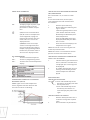
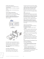
INSTALLATION AND MOUNTING
Instrument XR30C shall be mounted on
vertical panel, in a 29x71 mm hole, and fixed
using the special bracket supplied.
To obtain an IP65 protection grade use the
front panel rubber gasket (mod. RG-C) as
shown in figure.
The temperature range allowed for correct
operation is 0÷60 °C. Avoid places subject to
strong vibrations, corrosive gases, excessive
dirt or humidity. The same recommenda-
tions apply to probes. Let air circulate by the
cooling holes.
ELECTRICAL CONNECTIONS
The instrument is provided with screw
terminal block to connect cables with a
cross section up to 2,5 mm2. Before con-
necting cables make sure the power supply
complies with the instrument’s requirements.
Separate the probe cables from the power
supply cables, from the outputs and the
power connections. Do not exceed the
maximum current allowed on each relay, in
case of heavier loads use a suitable external
relay.
PROBE CONNECTION
The probes shall be mounted with the bulb
upwards to prevent damages due to casual
liquid infiltration. It is recommended to place
the thermostat probe away from air streams
to correctly measure the average room
temperature. Place the defrost termination
probe among the evaporator fins in the
coldest place, where most ice is formed,
far from heaters or from the warmest place
during defrost, to prevent premature defrost
termination.
HOW TO USE THE HOT KEY
HOW TO PROGRAM A HOT KEY FROM THE
INSTRUMENT (UPLOAD)
1. Program one controller with the front
keypad.
2. When the controller is ON, insert the “Hot
key” and push o key; the “uPL” message
appears followed a by flashing “End”
3. Push “SET” key and the End will stop flash
ing.
4. Turn OFF the instrument remove the “Hot
Key”, then turn it ON again.
NOTE: the “Err” message is displayed for
failed programming. In this case push again
key if you want to restart the upload again
or remove the “Hot key” to abort the opera-
tion.
HOW TO PROGRAM AN INSTRUMENT USING
A HOT KEY (DOWNLOAD)
1. Turn OFF the instrument.
2. Insert a programmed “Hot Key” into the
5 PIN receptacle and then turn the Con
troller ON.
3. Automatically the parameter list of the
“Hot Key” is downloaded into the
Controller memory, the “doL” message is
blinking followed a by flashing “End”.
4. After 10 seconds the instrument will restart
working with the new parameters.
5. Remove the “Hot Key”..
BRACKET
(PUSH TO RELEASE)
PANEL

User Instructions Low Temperature Freezers Model UNI/LT
11
NOTE: the message “Err” is displayed for
failed programming. In this case turn the
unit off and then on if you want to restart the
download again or remove the “Hot key” to
abort the operation.
ALARM SIGNALS
ALARM RECOVERY
Probe alarm “P1” starts some seconds after
the fault in the related probe; it automati-
cally stops some seconds after the probe
restarts normal operation. Check connec-
tions before replacing the probe.
Temperature alarms “HA” and “LA” auto-
matically stop as soon as the thermostat
temperature returns to normal values and
when defrost starts.
Alarms “EA” and “CA” (with i1F=bAL) re-
cover as soon as the digital input is
disabled.
Alarm “CA” (with i1F=PAL) recovers only by
switching off and on the instrument.
TECHNICAL DATA
Housing: self extinguishing ABS.
Case: XR30C frontal 32x74 mm; depth 60mm;
Mounting: XR30C panel mounting in a
71x29mm panel cut-out
Protection: IP20.
Frontal protection: IP65 with frontal gasket
RG-C (optional).
Connections: Screw terminal block ≤ 2,5
mm2 wiring.
Power supply: according to the model:
12Vac/dc, ±10%; 24Vac/dc, ±10%;
230Vac ±10%, 50/60Hz, 110Vac ±10%,
50/60Hz
Power absorption: 3VA max
Display: 3 digits, red LED, 14,2 mm high.
Inputs: 1 NTC or PTC probe.
Digital input: free contact
Relay outputs:
compressor: SPST relay 8(3) A, 250Vac or
SPST relay 20(8)A; 250Vac
second relay: SPDT relay 8(3) A, 250Vac or
Data storing: on the non-volatile memory
(EEPROM).
Kind of action: 1B; Pollution grade: normal;
Software class: A.
Operating temperature: 0÷60 °C.
Storage temperature: -30÷85 °C.
Relative humidity: 20÷85% (no condensing)
Measuring and regulation range:
NTC probe: -40÷110°C (-40÷230°F)
PTC probe: -50÷150°C (-58÷302°F)
Resolution: 0,1 °C or 1°C or 1 °F (selectable).
Accuracy (ambient temp. 25°C): ±0,7 °C ±1
digit
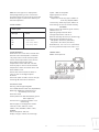
CONNECTIONS
XR30C: 8A compressor
Alarm signals;
Message
EE
P1
HA
LA
Cause
Date or memory failure
Probe failure
Max. temp. alarm
Min. temp. alarm

User Instructions Low Temperature Freezers Model UNI/LT
DEFAULT SETTING VALUES
Hidden parameters
12
Set
HY
LS
US
Ot
Ods
AC
CCt
COn
COF
CH
CF
rES
IdF
MdF
dFd
dAd
ALc
ALU
ALL
ALd
dAO
tbA
oA1
AoP
i1P
i1F
did
NpS
odc
PbC
rEL
Ptb
Set point
Differential
Minimum set point
Maximum setpoint
Thermostat probe calibration
Outputs delay at start up
Anti-short cycle delay
Continuos cycle duration
Compressor ON time with faulty probe
Compressor OFF time with faulty probe
Kind of action
Temperature measurement
Resolution
Interval between defrost cycles
(Maximum) length for defrost
Displaying during defrost
MAX display delay after defrost
Temp. alarmsconfiguration
MAXIMUM temp. alarm
Mimimum temp. alarm
Temperature alarm delay
Delay of temp. alarm at start up
Alarm relay silencing
2nd relay configuration
Second relay polarity (oA1=ALr)
Digital input polarity
Digital input configuration
Digital input delay
Number of activation of pressure switch
Compressor status with open door:
Kind of probe
Software release
Map code
Label Name Range °C/°F
3,0/37
2,0/4
-50,0/-58
110/230
0,0
0
1
0,0
15
30
CL
ºC/ºF
dE/-
8
20
it
30
Ab
LS+US
0,1-25,5ºC/ 1-255ºF
-50ºC-SET/ -58ºF-SET
SET-110ºC/ SET-230ºF
-12-12ºC/ -120-120ºF
0-255 min
0-50 min
0,0-24,0 h
0-255 min
0-255 min
CL=cooling Ht=heating
ºC - ºF
in=integer dE=dec. point
1-120 ore
0-255 min
rt, it, SEt, DEF
0-255 min
rE=related to set;
Ab=absolute
Set-110,0ºC; Set-230ºF
-50,0ºC-Set/ -58ºF-Set
0-255 min
0-23 h e 50´
n=no y=yes
ALr=alarm; dEF=no select it;
LHt=auxiliary; onF=always on:
Fan=no select it
oP; cL
oP=opening; CL=closing
EAL=extern alarm; bAL=lock
regulation; PAL=press switch;
dor=door switch; dEF=defrost
LHt=switch on 2nd relay;
Htr=cooling - heating
0-255 min
0-15
no, Fan=normal;
CPr; F_C=Compr. OFF
Ptc; ntc
--
--
110/230
-50/-58
15
1,3
Y
LHt
cL
cL
LHt
5
15
no
ntc/Ptc
4,0
-

User Instructions Low Temperature Freezers Model UNI/LT
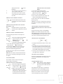
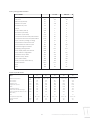
Factory settings UNI/LT models.
Technical specifications:
13
Description
Set point
Different (Hysteresis)
Minimum set point
Maximum set point
Offset
Output delay start up
Anti-short cycle delay
Continious cycle delay
Compressor ON time with probe failure
Compressor OFF time with probe failure
Type of action (cooling, heating)
Temperature measurement unit
Interval between defrost cycles
Maximum lenght for defrost
Displaying during defrost
Max. display delay after defrost
Temp. alarms configuration
Maximum temp. alarm
Minimum temp. alarm
Temp. alarm delay
Delay of temp. alarm start up
Probe selection
N/A
N/A
Label
Set
Hy
LS
US
Ot
Ods
AC
CCt
COn
COF
CH
CF
ldF
Mdf
dFd
dAd
Alc
ALU
ALL
Ald
dAo
PbC
Rel
Ptb
Dixell XR30C 115 volt
Setting Celcius
-45
3
-50
0
0
1
3
0
60
5
CL
C
120
0
Set
1
Ab
-36
-50
120
24
Ptc
3
84
Setting Farenheit
-45
3
-58
0
0
1
3
0
60
5
CL
F
120
0
Set
0
Ab
-33
-58
120
24
Ptc
3
84
230 volt
Ambient temperature
Gross volume
Gross volume
Height on feet
Height with open lid
Width
Insulation thickness
Depth excl. handle and hinges
Power consumption UNI/LT at +25˚ C
Fuse
Temeprature range UNI/LT
Noise level UNI/LT
Weight
˚C
litres
cu. ft.
mm
mm
mm
mm
mm
Watts
A
˚C
dBa
kg
+10˚ to +30˚
130
4,6
860
1560
720
100
730
210
10
-30˚ to -45˚
< 51
50
+10˚ to +30˚
227
8,0
860
1560
1055
100
730
360
10
-30˚ to -45˚
< 51
63
+10˚ to +30˚
301
10,6
860
1560
1300
100
730
360
10
-30˚ to -45˚
< 51
75
11 21 31
UNI/LT
5141
+10˚ to +30˚
360
12,7
860
1560
1500
100
730
400
10
-30˚ to -45˚
< 51
80
+10˚ to +30˚
418
14,8
860
1560
1700
100
730
420
10
-30˚ to -45˚
< 51
92
(230V 50Hz)

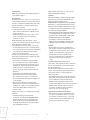
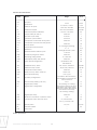
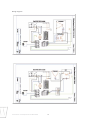
User Instructions Low Temperature Freezers Model UNI/LT
14
Wiring diagrams
Censor
Power supply
230V
50/60 HZ
Power supply
230V
50/60 HZ
Censor

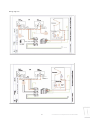
User Instructions Low Temperature Freezers Model UNI/LT
15
Wiring diagrams
Power
supply
115V
60 HZ
Censor
Power
supply
Censor
115V 60 HZ

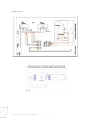
User Instructions Low Temperature Freezers Model UNI/LT
Wiring diagrams
Power
supply
115V
60 HZ
Censor
16

User Instructions Low Temperature Freezers Model UNI/LT
17
-
 1
1
-
 2
2
-
 3
3
-
 4
4
-
 5
5
-
 6
6
-
 7
7
-
 8
8
-
 9
9
-
 10
10
-
 11
11
-
 12
12
-
 13
13
-
 14
14
-
 15
15
-
 16
16
-
 17
17
-
 18
18


AccuCold EL21LT Owner's manual
- Category
- Fridge-freezers
- Type
- Owner's manual
Ask a question and I''ll find the answer in the document
Finding information in a document is now easier with AI
Related papers
Other documents
-
 UNI DEVICE JO-UQM10A User manual
-
Emerson Dixell XR10C Installating And Operating Instructions
-
 ThermoMart DWH7016M Owner's manual
-
Frigor GLE 30 User Instructions
-
 ThermoMart DWH7016V Owner's manual
-
dixell XT11CX Owner's manual
-
-
-
Norlake NL708 Door Alarm Installation, Operation And Maintenance Instructions
-


