Peavey PVXp 15 DSP 830-Watt 15 inch Powered Speaker Owner's manual
- Category
- Audio amplifiers
- Type
- Owner's manual
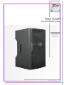
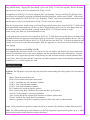
Peavey PVXp 15 DSP 830-Watt 15 inch Powered Speaker
This speaker provides a total of 830 Watts of peak available dynamic power and features a reliable bi-amped power section. It includes heavy-duty speaker drivers, a 15” woofer with a 2-3/8” voice coil and a 50 oz. magnet, coupled with the RX14 compression driver that includes a 1.4” titanium diaphragm on a 100-degree horizontal x 50-degree vertical pattern asymmetrical horn.
Advanced digital signal compression prevents audible overload, protecting the speakers from harmful distortion at high output levels.


-
 1
1
-
 2
2
-
 3
3
-
 4
4
-
 5
5
-
 6
6
-
 7
7
-
 8
8
-
 9
9
-
 10
10
-
 11
11
-
 12
12
-
 13
13
-
 14
14
-
 15
15
-
 16
16
-
 17
17
-
 18
18


Peavey PVXp 15 DSP 830-Watt 15 inch Powered Speaker Owner's manual
- Category
- Audio amplifiers
- Type
- Owner's manual
Peavey PVXp 15 DSP 830-Watt 15 inch Powered Speaker
This speaker provides a total of 830 Watts of peak available dynamic power and features a reliable bi-amped power section. It includes heavy-duty speaker drivers, a 15” woofer with a 2-3/8” voice coil and a 50 oz. magnet, coupled with the RX14 compression driver that includes a 1.4” titanium diaphragm on a 100-degree horizontal x 50-degree vertical pattern asymmetrical horn.
Advanced digital signal compression prevents audible overload, protecting the speakers from harmful distortion at high output levels.
Ask a question and I''ll find the answer in the document
Finding information in a document is now easier with AI
Related papers
-
Peavey PVXp 12 DSP 830-Watt 12 inch Powered Speaker Owner's manual
-
-
-
-
-
Peavey AQ 12 Enclosure Speaker User manual
-
-
-
-
Other documents
-
Fostex FT17H User manual
-
Giant RGBICW User manual
-
Rolls RDB109 User manual
-
Clinton Electronics CE-CMHL-EX User manual
-
 PYLE Audio PPFR212 User manual
-
 PYLE Audio PRO PPHP1259 User manual
-
 W Audio Gig Rig 2 User manual
-
 Motion Sound KM-12 Owner's manual
-
AUDIOTONE PROFESSIONAL MU-15DSP User manual
-
Qtx 178.230UK User manual


