
Professional Digital DJ Mixer
OWNER’S MANUAL
CAUTION: TO REDUCE THE RISK OF ELECTRIC SHOCK, DO NOT
REMOVE COVER (OR BACK). NO USER-SERVICEABLE PARTS
INSIDE. REFER SERVICING TO QUALIFIED SERVICE PERSONNEL.
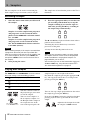
The exclamation point within an equilateral triangle is intended to alert the user to the pres-
ence of important operating and maintenance (servicing) instructions in the literature
accompanying the appliance.
The lightning flash with arrowhead symbol, within an equilateral triangle, is intended to alert
the user to the presence of uninsulated “dangerous voltage” within the product’s enclosure
that may be of sufficient magnitude to constitute a risk of electric shock to persons.
This appliance has a serial number
located on the bottom. Please record
the model number and serial number
and retain them for your records.
Model number
Serial number
Ü
ÿ
Ÿ
WARNING: TO PREVENT FIRE OR SHOCK
HAZARD, DO NOT EXPOSE THIS
APPLIANCE TO RAIN OR MOISTURE.

2 TASCAM X-9 Owner’s Manual
Important Safety Precautions
IMPORTANT (for U.K. Customers)
DO NOT cut off the mains plug from this equipment.
If the plug fitted is not suitable for the power points in your home or
the cable is too short to reach a power point, then obtain an
appropriate safety approved extension lead or consult your dealer.
If nonetheless the mains plug is cut off, remove the fuse
and dispose
of the plug immediately, to avoid a possible shock hazard by
inadvertent connection to the mains supply.
If this product is not provided with a mains plug, or one has to be
fitted, then follow the instructions given below:
IMPORTANT: DO NOT make any connection to the larger
terminal which is marked by the letter E or by the safety earth
symbol ç
or coloured GREEN or GREEN-and-YELLOW.
The wires in this mains lead are coloured in accordance with the
following code:
BLUE : NEUTRAL
BROWN : LIVE
As the colours of the wires in the mains lead of this apparatus may
not correspond with the coloured markings identifying the terminals
in your plug proceed as follows:
The wire which is coloured BLUE must be connected to the terminal
which is marked with the letter N or coloured BLACK.
The wire which is coloured BROWN must be connected to the
terminal which is marked with the letter L or coloured RED.
When replacing the fuse only a correctly rated approved type should
be used and be sure to re-fit the fuse cover.
IF IN DOUBT — CONSULT A COMPETENT ELECTRICIAN.
TO THE USER
This equipment has been tested and found to
comply with the limits for a Class A digital device,
pursuant to Part 15 of the FCC Rules. These
limits are designed to provide reasonable
protection against harmful interference when the
equipment is operated in a commercial
environment. This equipment generates, uses,
and can radiate radio frequency energy and, if
not installed and used in accordance with the
instruction manual, may cause harmful
interference to radio communications.
Operation of this equipment in a residental area
is likely to cause harmful interference in which
case the user will be required to correct the
interference at his own expense.
CAUTION
Changes or modifications to this equipment not
expressly approved by TEAC CORPORATION
for compliance could void the user’s authority to
operate this equipment.
For the consumers in Europe
WARNING
This is a Class A product. In a domestic environment, this
product may cause radio interference in which case the user
may be required to take adequate measures.
Pour les utilisateurs en Europe
AVERTISSEMENT
Il s’agit d’un produit de Classe A. Dans un environnement
domestique, cet appareil peut provoquer des interférences
radio, dans ce cas l’utilisateur peut être amené à prendre
des mesures appropriées.
Für Kunden in Europa
Warnung
Dies is eine Einrichtung, welche die Funk-Entstörung nach
Klasse A besitzt. Diese Einrichtung kann im Wohnbereich
Funkstörungen versursachen ; in diesem Fall kann vom
Betrieber verlang werden, angemessene Maßnahmen
durchzuführen und dafür aufzukommen.
For U.S.A
The equipment draws nominal non-operating power from the
AC outlet with its POWER switch in the off position.

TASCAM X-9 Owner’s Manual 3
CAUTION:
…Read all of these Instructions.
…Save these Instructions for later use.
…Follow all Warnings and Instructions marked on the audio
equipment.
1) Read Instructions — All the safety and operating instructions should
be read before the product is operated.
2) Retain Instructions — The safety and operating instructions should
be retained for future reference.
3) Heed Warnings — All warnings on the product and in the operating
instructions should be adhered to.
4) Follow Instructions — All operating and use instructions should be
followed.
5) Cleaning — Unplug this product from the wall outlet before cleaning.
Do not use liquid cleaners or aerosol cleaners. Use a damp cloth for clean-
ing.
6) Attachments — Do not use attachments not recommended by the
product manufacturer as they may cause hazards.
7) Water and Moisture — Do not use this product near water — for
example, near a bath tub, wash bowl, kitchen sink, or laundry tub; in a wet
basement; or near a swimming pool; and the like.
8) Accessories — Do not place this product on an unstable cart, stand,
tripod, bracket, or table. The product may fall, causing serious injury to a
child or adult, and serious damage to the product. Use only with a cart,
stand, tripod, bracket, or table recommended by the manufacturer, or sold
with the product. Any mounting of the product should follow the manufac-
turer’s instructions, and should use a mounting accessory recommended by
the manufacturer.
9) A product and cart combination should be moved with care. Quick stops,
excessive force, and uneven surfaces may cause the product and cart com-
bination to overturn.
10) Ventilation — Slots and openings in the cabinet are provided for ven-
tilation and to ensure reliable operation of the product and to protect it from
overheating, and these openings must not be blocked or covered. The open-
ings should never be blocked by placing the product on a bed, sofa, rug, or
other similar surface. This product should not be placed in a built-in instal-
lation such as a bookcase or rack unless proper ventilation is provided or
the manufacturer’s instructions have been adhered to.
11) Power Sources — This product should be operated only from the
type of power source indicated on the marking label. If you are not sure of
the type of power supply to your home, consult your product dealer or local
power company. For products intended to operate from battery power, or
other sources, refer to the operating instructions.
12) Grounding or Polarization — This product may be equipped with a
polarized alternating-current line plug (a plug having one blade wider than
the other). This plug will fit into the power outlet only one way. This is a
safety feature. If you are unable to insert the plug fully into the outlet, try
reversing the plug. If the plug should still fail to fit, contact your electrician
to replace your obsolete outlet. Do not defeat the safety purpose of the
polarized plug.
13) Power-Cord Protection — Power-supply cords should be routed so
that they are not likely to be walked on or pinched by items placed upon or
against them, paying particular attention to cords at plugs, convenience
receptacles, and the point where they exit from the product.
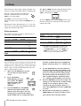
14) Outdoor Antenna Grounding — If an outside antenna or cable
system is connected to the product, be sure the antenna or cable system is
grounded so as to provide some protection against voltage surges and built-
up static charges. Article 810 of the National Electrical Code, ANSI/NFPA
70, provides information with regard to proper grounding of the mast and
supporting structure, grounding of the lead-in wire to an antenna discharge
unit, size of grounding conductors, location of antenna-discharge unit, con-
nection to grounding electrodes, and requirements for the grounding elec-
trode.
"Note to CATV system installer:
This reminder is provided to call the CATV system installer’s attention to
Section 820-40 of the NEC which provides guidelines for proper grounding
and, in particular, specifies that the cable ground shall be connected to the
grounding system of the building, as close to the point of cable entry as
practical.
15) Lightning — For added protection for this product during a lightning
storm, or when it is left unattended and unused for long periods of time,
unplug it from the wall outlet and disconnect the antenna or cable system.
This will prevent damage to the product due to lightning and power-line
surges.
16) Power Lines — An outside antenna system should not be located in
the vicinity of overhead power lines or other electric light or power circuits,
or where it can fall into such power lines or circuits. When installing an
outside antenna system, extreme care should be taken to keep from touch-
ing such power lines or circuits as contact with them might be fatal.
17) Overloading — Do not overload wall outlets, extension cords, or
integral convenience receptacles as this can result in risk of fire or electric
shock.
18) Object and Liquid Entry — Never push objects of any kind into
this product through openings as they may touch dangerous voltage points
or short-out parts that could result in a fire or electric shock. Never spill
liquid of any kind on the product.
19) Servicing — Do not attempt to service this product yourself as open-
ing or removing covers may expose you to dangerous voltage or other
hazards. Refer all servicing to qualified service personnel.
20) Damage Requiring Service — Unplug this product from the wall
outlet and refer servicing to qualified service personnel under the following
conditions:
a) when the power-supply cord or plug is damaged.
b) if liquid has been spilled, or objects have fallen into the product.
c) if the product has been exposed to rain or water.
d) if the product does not operate normally by following the operating
instructions. Adjust only those controls that are covered by the operating
instructions as an improper adjustment of other controls may result in
damage and will often require extensive work by a qualified technician to
restore the product to its normal operation.
e) if the product has been dropped or damaged in any way.
f ) when the product exhibits a distinct change in performance – this
indicates a need for service.
21) Replacement Parts — When replacement parts are required, be sure
the service technician has used replacement parts specified by the manufac-
turer or have the same characteristics as the original part.
Unauthorized substitutions may result in fire, electric shock, or other
hazards.
22) Safety Check — Upon completion of any service or repairs to this
product, ask the service technician to perform safety checks to determine
that the product is in proper operating condition.
23) Wall or Ceiling Mounting — The product should be mounted to a
wall or ceiling only as recommended by the manufacturer.
24) Heat — The product should be situated away from heat sources such
as radiators, heat registers, stoves, or other products (including amplifiers)
that produce heat.
ANTENNA
LEAD IN
WIRE
ANTENNA
DISCHARGE UNIT
(NEC SECTION 810-20)
GROUNDING CONDUCTORS
(NEC SECTION 810-21)
GROUND CLAMPS
POWER SERVICE GROUNDING
ELECTRODE SYSTEM
(NEC ART 250. PART H)
NEC - NATIONAL ELECTRICAL CODE
ELECTRIC
SERVICE
EQUIPMENT
Example of Antenna Grounding as per
National Electrical Code, ANSI/NFPA 70
GROUND
CLAMP
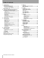
IMPORTANT SAFETY INSTRUCTIONS

Table of Contents
4 TASCAM X-9 Owner’s Manual
1 – Introduction
Some notes and precautions ...................... 5
Environmental considerations ............................... 5
Connections to other equipment ...........................5
Serial number, etc. ....................................... 5
2 – Getting acquainted with the X-9
Road map to front panel functions ............ 6
Program gain level, EQ and assignment section ..6
Sampler section ....................................................... 7
Microphone control ................................................ 7
Cue selection keys and monitor keys ....................7
Master fader ............................................................ 8
Program faders ........................................................ 8
External effect .........................................................8
Cross-fader and fader controls ............................... 9
Effect, menu, etc. management .............................9
3 – Connections
Record turntables .................................................. 10
CD decks, etc. .........................................................10
Digital connections ............................................... 10
Amplifier system ...................................................10
Booth outputs .......................................................11
Microphone (connection and use) .......................11
External effects unit .............................................. 12
Headphones (connecting and using) ...................12
Fader start/stop connections ................................12
Footswitches .......................................................... 12
External effects .....................................................13
4 – Learning more
About programs ........................................ 14
Assigning sources to programs ............................ 14
Trim .................................................................... 14
Cross-fading ............................................... 14
Signal flow .............................................................15
Playing a song ............................................ 16
Adjusting the output volume ................... 16
Cue (previewing sounds) .......................... 16
5 – Menus
How the X-9 shows characters ..................17
Menu reference ..........................................17
6 – Faders
Program fader “curve” ...............................21
Program fader direction ............................21
Fader start ...................................................21
Cross-fader curve .......................................22
Cross-fader start .........................................22
Cross-fader reverse ....................................22
7 – Effects
Selecting the effect type .......................................23
Editing the effects .................................................23
The BEAT parameter ..............................................23
Effect parameters ..................................................24
Storing effects .......................................................24
Recalling stored effect settings ............................25
8 – Samplers
Recording a sample ....................................26
Playing back samples .................................26
Editing samples ..........................................27
Erasing samples ..........................................27
Sample pitch ...............................................27
9 – EQ
EQ Q setting ...........................................................28
Cutting the EQ bands ............................................28
Viewing EQ settings ..............................................28
Remembering and recalling EQ settings ..............29
10 – Specifications, etc.
I/O specifications ........................................30
Audio I/O ................................................................30
Control I/O .............................................................30
Audio specifications ...................................31
General specifications ...........................................31
Dimensional drawing .................................32
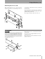
Mounting the X-9 in a rack ........................33
Case mounting .......................................................33
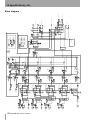
Block diagram .............................................34

TASCAM X-9 Owner’s Manual 5
1 – Introduction
The X-9 is a sophisticated DJ mixer which allows the
connection of many devices, and allows you to mix
in a creative way, adding effects, taking samples, etc.
and crossfading between sources.
Following the standard design pattern for such a
device, the X-9 combines easy operation with a wide
range of functions.
Smooth faders, easy-to-use controls and clear indica-
tors displays allow you to concentrate on the music,
not the operation of the unit.
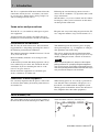
Some notes and precautions
Treat the X-9 as you would any other piece of preci-
sion equipment.
Avoid exposing it to extremes of temperature and
humidity and avoid mechanical shocks and vibration.
Keep the unit away from strong magnetic fields (TV
sets, computer monitors, large electric motors, etc.).
Environmental considerations
The X-9 may be used in most areas, but to maintain
top performance, and prolong operating life, observe
the following environmental conditions:
The nominal temperature should be between 5°C and
35°C (41°F and 95°F).
Relative humidity should be 30 to 90 degrees non-
condensing.
As the unit may become hot during operation, always
leave sufficient space above and around the unit for
ventilation. If you are mounting the unit in a rack,
leave 1U of space above it.
Do not install this equipment in a confined space
such as a bookcase or similar unit.
You should not place the unit on a piece of equip-
ment generating heat, e.g. an amplifier, to avoid pos-
sible problems with overheating.
The voltage supplied to the unit should match the
voltage as printed on the rear panel. If you are in any
doubt regarding this matter, consult an electrician.
NOTE
When transporting the unit, always use the original
packing materials or a properly-designed equipment
case. For this reason, we strongly recommend that you
save all the packing materials that came with the X-9, in
case you need to transport it in the future.
Connections to other equipment
It is extremely important that the power is turned off
on all units when making or breaking connections to
or from the X-9.
When turning power on, it is usually a good idea to
start with the source (turntables, CD players, etc.),
then the X-9 and finish with the amplifier system.
Turning power off should be done in the other direc-
tion (amplifiers first, then other equipment).
Serial number, etc.
The serial number of the X-9 is located on a sticker at
the front of the unit on the bottom panel. Make a note
of this for future reference (warranty, etc.).

6 TASCAM X-9 Owner’s Manual
2 – Getting acquainted with the X-9
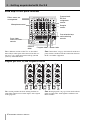
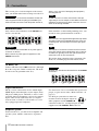
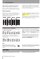
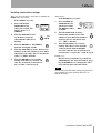
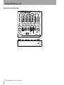
Road map to front panel functions
These different sections of the X-9 are described
more fully in other parts of the manual, but this sec-
tion gives you a quick orientation to help you find
your way around the mixer.
See “Connections” on page 10 for details of the rear
panel features and how to make connections between
the X-9 and other equipment.
Program gain level, EQ and assignment section
This section provides the basic mixing facilities to
control the sound received at the inputs, and assigned
to the programs.
See “About programs” on page 14 for details of how
inputs and programs work together and how to use
these controls.
Sampler
section
Program level,
EQ and
assignment
section
Microphone control
Cue selection keys
and monitoring
controls
Cross-fader
and cross-fader
controls
Effect, menu, etc.
management
Program faders
Master fader
External
effect

2 Getting acquainted with the X-9
TASCAM X-9 Owner’s Manual 7
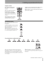
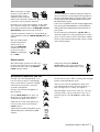
Sampler section
The sampler section provides
the controls for two built-in
samplers.
These are capable of accepting
the input from a variety of
sources (program, microphone
or master mix), and recording
eight seconds of sound (for each
sampler).
You can then play the resulting
sample from the X-9, cue it, etc.
and add it to the overall mix.
Samplers can be assigned to the cross-fader signals,
and the cross-fader can be used to start them.
See “Samplers” on page 26 for full details of how to
operate these samplers.
Microphone control
This section provides control over the
microphone.
A talkover function, as well as 2-band
EQ, is provided in this section for use
with the microphone.
See “Microphone (connection and
use)” on page 11 for full details of how
to use the microphone with the X-9.
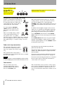
Cue selection keys and monitor keys
These keys allow the selection of the programs,
microphone, sampler, etc. for cueing and preview.
The headphones are used for this purpose, and the
booth outputs may be used to provide a second set of
stereo outputs.
See “Headphones (connecting and using)” on
page 12 and “Cue (previewing sounds)” on page 16
for details.

2 Getting acquainted with the X-9
8 TASCAM X-9 Owner’s Manual
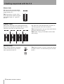
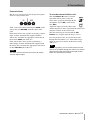
Master fader
The master fader is used to control
the overall level of the mixed signal
output from the X-9.
See “Signal flow” on page 15 for
details of how this works in conjunc-
tion with the input, etc., signals in
the X-9.
Program faders
These faders adjust the levels of the programs after
they have been equalized and before they are sent to
either the cross-fader or to the master fader.
The fader curve and fader direction can also be set,
and fader program start can be carried out.
See “About programs” on page 14 for details of how
programs and signals interact.
See “Faders” on page 21 for further details about
fader settings.
External effect
These controls affect the assignment
and the on/off status of any external
effect connected to the X-9.
See “External effects” on page 13 for details of how
to connect and use an external effect processor with
the X-9.

2 Getting acquainted with the X-9
TASCAM X-9 Owner’s Manual 9
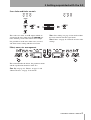
Cross-fader and fader controls
These take care of the A and B outputs which are
assigned to the cross-fader using the
ASSIGN con-
trols, and then passed to the master stereo output.
It is possible to set the cross-fader curve, reversal,
and allow source starting with the cross-fader.
See “Cross-fading” on page 14 for details of how
the cross-fader fits into the signal chain.
See “Faders” on page 21 for details of cross-fader
settings.
Effect, menu, etc. management
This section handles the effects, the parameter menus
and the equalization memories of the X-9.
See “EQ” on page 28, “Effects” on page 23 and
“Menu reference” on page 17 for details.

10 TASCAM X-9 Owner’s Manual
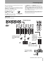
3 – Connections
This section gives a brief description of the connec-
tions you should make before starting to use the X-9.
WARNING
Make and break all connections between the X-9 and
other equipment with everything turned
OFF
. If you
make or break connections with the power turned on,
there is a very real risk of damaging the equipment,
including the X-9.
NOTE
All XLR connectors on the X-9 are wired so that pin
1=ground, pin 2= hot and pin 3=cold. Make sure that all
equipment connected using these connectors also con-
forms to this wiring standard.
Record turntables
Only connect record turntables to the PHONO con-
nectors (
1, 2, 3 or 4).
WARNING
Never connect record turntables to any other type of
connector on the X-9.
Never connect any other type of equipment to the
PHONO
connectors.
If the turntables are fitted with grounding wires, con-
nect these to the ground terminals on the X-9.
NOTE
Note that the X-9 is supplied with eight RCA caps which
should be fitted over the PHONO terminals if they are
not being used. This will help to maintain high signal
quality.
TIP
The X-9 pairs of connectors all have the left connector
at the top and the right at the bottom. Pairs of pin sig-
nal cables are typically red for the right channel and
some other color for the left channel.
We explain about connecting other equipment (CD
decks, etc.) including digital connections, below.
CD decks, etc.
Connect CD decks to the LINE connectors (1 through
4) on the rear panel. Unlike record decks, CD decks
do not need to be grounded to the X-9).
WARNING
CD decks, etc. should never be attached to the
PHONO
connections.
Digital connections
The X-9 can be connected to devices which output
SPDIF digital audio through a coaxial output (many
CD players, MD players and DATs, as well as some
electronic musical instruments) and can also output a
digital audio version of the final mix (to a digital
recorder such as a DAT, or a CD recorder, or a suit-
ably-equipped personal computer).
Use menu item 14dl to set whether the signal is out-
put pre- or post- master fader (“Menu reference” on
page 17).
Use RCA pin jack cables to make con-
nections between the digital outputs of
other equipment and the
DIGITAL IN
connectors of the X-9, and digital inputs of other
equipment and the
DIGITAL OUT of the X-9.
Amplifier system
To listen to the X-9, you will need an amplifier and
speaker system, which is connected as explained
here.

3 Connections
TASCAM X-9 Owner’s Manual 11
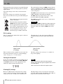
When connecting an ampli-
fication system to the X-9,
check the inputs of the
amplifier. If they look like
either of the connectors shown here, they are XLR
connectors and are probably balanced.
Check the rear panel of the amplifier, or the ampli-
fier’s manual, to make sure. Amplifiers with bal-
anced inputs should be fed by the
MASTER OUTPUT
(BALANCED)
output connectors of the X-9.
All other connectors (mono 1/4” jack or RCA pin
jacks should be fed by the
(UNBALANCED) RCA pin
outputs.
The level of the output
from the unbalanced
outputs can be set
using the
PRE/POST
switch to be affected
by the master fader
(
POST) or unaffected
by it (
PRE).
WARNING
It is most important to make sure that you make the
correct connections. Connecting the wrong output of
the X-9 to the amplification system can result in over-
heating and possible damage to both the X-9 and to
the amplification system.
If you are in any doubt at all, we strongly suggest that
you consult your TASCAM dealer or other qualified
audio professional regarding the interconnection of
your system.
Use the trimmer potentiometers (LEVEL ATT) to
adjust the output level to the amplification systems.
Again, you may find it useful to consult the amplifi-
cation system documentation and/or consult a profes-
sional sound engineer.
Booth outputs
The booth outputs provide you with a sec-
ond mix where the level is not controlled
by the master fader, but by the
BOOTH
LEVEL
volume control.
Connect the unbalanced
BOOTH
OUTPUT
RCA jacks to the unbalanced
inputs of the booth amplification system.
Microphone (connection and use)
To input your voice through the X-9 sys-
tem, you need to connect a microphone
to the system. The X-9 provides an XLR
connector for connecting a standard
(dynamic) microphone.
Connect your favorite microphone to
this connector.
Use the
TALK OVER key to “dim” all
the signals except the microphone by
20 dB (the key lights when active).
Adjust the level of the microphone sig-
nal sent to the master fader with the
LEVEL control.
Adjust the tone of the microphone signal
with the
HI (treble) and LO (bass) EQ
controls.
Use the menu system (
18bm) to change the left-right
balance of the microphone signal.
You can also select the microphone signal to be
passed through the internal or external effects, as
well as being used as a source for sampler 1.
The microphone signal can be cued (see “Cue (pre-
viewing sounds)” on page 16) in the same way as
program signals, using the
CUE key (lights when
active).
or

3 Connections
12 TASCAM X-9 Owner’s Manual
External effects unit
Use the SEND and
RETURN 1/4” jacks to
connect any external
effects unit. For full
details of connection and use of an external unit, see
“External effects” on page 13
Headphones (connecting and using)
Connect a standard pair of stereo head-
phones to the stereo 1/4” jack on the top
or at the front of the X-9. These two
jacks output the same signals and are
controlled by the same controls.
Use the headphone
PHONES
LEVEL
control to adjust the vol-
ume of the signal from the head-
phones.
There are four EQ settings, which
can be made using the menu sys-
tem (menu
01HP)—see “Menu
reference” on page 17. These settings boost either the
low or the high part of the frequency range, or both.
The fourth setting is a “normal” setting—no cut or
boost.
The balance between the cue mix (see “Cue (pre-
viewing sounds)” on page 16) and the master cue
mix in the headphones is set using the upper
PHONES control. Turn counterclockwise for cue sig-
nals (
CUE) and clockwise for main master cue mix
(
MST).
In addition, the headphone output can be in stereo
outputs or set so that the left headphone outputs the
cue signal (in mono, of course) and the right head-
phone outputs the master main signal (in mono).
Use the STEREO (the indicator is unlit)/
MONO
SPLIT
(indicator is lit) key to change between these
two modes.
In the
MONO SPLIT mode, the cue signal is output
from the left headphone, and the master cue signal
from the right headphone. Use the
CUE/MST control
to adjust the relative levels.
Fader start/stop connections
The four mono mini-jacks (3.5 mm)
are connected so that the tip feeds a
fader start, and the sleeve feeds a fader
stop.
The ground for these connections is
provided by the signal ground of the device to which
the fader start is made.
NOTE
Even if the device is connected digitally to the X-9 (such
as a CD or MD player) for the audio connection, an ana-
log connection must also be made to provide the
ground for the fader start.
Note that the fader start control refers to the program
number—see “About programs” on page 14 (not the
device number).
To activate fader start/stop for individual programs,
follow the instructions in “Fader start” on page 21.
To activate fader start/stop for the devices assigned to
the cross-fader signals, follow the instructions in
“Cross-fader start” on page 22.
Footswitches
You can connect one or two
(optional) footswitches, such as
the TASCAM RC-30P model, to
the X-9’s
FOOT SW jacks.
These footswitches can be used for a variety of pur-
poses, such as sampler control, effect on and off, etc.
Use the menu item (
08Ft) (“Menu reference” on
page 17) for full details of how these switches can be
set up.

3 Connections
TASCAM X-9 Owner’s Manual 13
External effects
The X-9 can send signals to and accept return signals
from an external effects unit.
Such a unit can be connected using the
SEND (to the
effects unit) and
RETURN (from the effects unit)
jacks.
If the effects unit is only capable of accepting a mono
input, read the documentation supplied with the
effects unit, and make the appropriate connection to
the
L effect SEND jack of the X-9.
If the effects unit is only capable of producing a
mono output, read the documentation supplied with
the effects unit, and make the appropriate connection
to the
L RETURN jack of the X-9.
NOTE
The return from the external input cannot be output
from the digital output.
To use the external effects unit
Turn the EFFECT IN knob to select the
signal that will be processed by the
effects unit: a program (
1 through 4), the
microphone signal (
MIC) or the master
mix (
MST).
Adjust the input level to the effects unit
and the output level of the signal from the effects unit
using the controls of the external unit.
Turn the effect loop on and off with the
EXT
EFFECT
key (it lights when the loop is active).
It is also possible to use an external effects unit
through the footswitches (see “Footswitch assign-
ment” on page 18 for details of this menu setting
(
08Ft))).
TIP
For a strange effect, you can send and return the left
channel of a program through one effects unit, and the
right channel of the same program through another
effects unit with different settings.

14 TASCAM X-9 Owner’s Manual
4 – Learning more
The X-9 has four sets of inputs, as well as the two
built-in samplers and the microphone input, all of
which can be mixed and used as sound sources.
There are a number of different signals that can be
fed into the X-9: up to four turntables, and four other
analog devices, and two digital devices, not to men-
tion the two internal samplers and the microphone.
In order to understand the X-9, it is necessary to get a
basic idea of where the signals go.
About programs
These inputs are assigned to four mixer channels
(modules), known as programs, and numbered from
1 through 4, The levels of the programs are con-
trolled using program faders.
In addition, each program is equipped with 3-band
sweppable sweepable EQ, with variable Q, and a trim
control.
The left-right balance of each program is adjusted
using the menu system with
19b1, 20b2, 21b3 and
22b4 (see “Menu reference” on page 17).
Assigning sources to programs
Use the switches on the top panel to change between
the
LINE and PHONO inputs.
In addition, there is a key beside each of these
switches, allowing you to choose different sources
for the programs:
The keys for programs 1 and 2 allow the digital
inputs to be selected as an alternative to the PHONO/
LINE
pair. When the indicators for these keys are lit
(the digital is selected), the
PHONO/LINE switch has
no effect.
The keys for programs 3 and 4 allow input 2 to be
selected for program 3 and/or input 1 to be selected
for program 4. The meaning of inputs 1 and 2 is
decided by the
PHONO/LINE switches for 1 and 2
and by the digital selection keys.
Trim
When the inputs have been assigned,
adjust the level fed to the equalizer, and
then the fader, using the program’s
TRIM
control.
This provides 38 dB of adjustment. Note that turning
this control too far clockwise with a powerful input
signal may result in a distorted signal.
Cross-fading
When the two program sources have been assigned
as shown above (“About programs” on page 14), they
can be transferred to the outputs through the cross-
fader and then through the master fader.

4 Learning more
TASCAM X-9 Owner’s Manual 15
The two signals that are controlled by the cross-fader
are known as
A and B.
You can set these to be any of the following using the
ASSIGN A and ASSIGN B controls below and to the
right and left of the program faders:
Programs 1 through 4, a sam-
pler (
SAMP 1 for A, and
SAMP 2 for B) or THRU.
The
THRU setting is equivalent
to OFF. In other words, if either
the
ASSIGN A or the ASSIGN B control is set to
THRU, no signal is assigned to go through the cross-
fader on that side, and moving the cross-fader to the
side with the
THRU setting has no effect on that side.
When
THRU is selected, use the appropriate program
fader(s) and the master fader.
Move the fader from the left (fully A signal only) to
the right (fully B signal only) to perform the cross-
fade between the two signals.
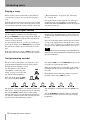
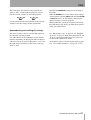
Signal flow
The signal flow is therefore:
Note that this is SAMP1
for the ASSIGN A control
Incoming signals are
assigned to programs
Programs (and samplers)
are assigned to the
cross-fader A and B
signals
Programs (and
samplers not
assigned to the
cross-fader) go
straight to the
master, together
with the mic
The cross-fader
determines the A and B
levels sent to the master
The master outputs
(what your audience
hears)

4 Learning more
16 TASCAM X-9 Owner’s Manual
Playing a song
When you have made connections as described in
“Connections” on page 10, you can start playing a
song.
With the program fader at its lowest level (0) and the
master fader also at 0, load a CD in the player, or put
a record on the turntable connected in the earlier step
(“Record turntables” on page 10 and “CD decks,
etc.” on page 10).
Cue up the CD or record using the cue functions as
described below (use headphones to monitor the
CUE output while the
CUE indicator for the program
with the record is lit).
Adjusting the output volume
Set the amplifier volume to less than full setting.
Bring the
MASTER fader up to about the 7 mark, and
slowly bring adjust the program fader until the over-
all level is what you want.
Use the program meter to view the level of the pro-
gram signal, and the stereo
MASTER meters to check
the overall level of the signal fed from the X-9 out-
puts.
If the top segment of a meter (
14 dB) is lit for most
of the time, the sound coming out of the X-9 will be
distorted. You should therefore try to keep the level
so that the red segments of the meters are not lit all
the time.
You can set the time that the meters take to fall back,
as well as the time that they hold peak values, using
the
12Mr and 13Mp menus (see “Meter release time”
on page 19 and “Meter peak hold time” on page 19).
TIP
We suggest this way of working to avoid possible over-
loading of the internal amplifiers, and distortion caused
by such overloading.
Cue (previewing sounds)
The X-9’s cue system allows you to preview a pro-
gram through headphones before playing it back
through the main amplifier system.
Use the controls as described in
“Headphones (connecting and
using)” on page 12 to select the
cue output to the headphones.
Press any of the program
CUE
keys, the microphone
CUE key,
the sampler
CUE key or the MASTER cue key to lis-
ten to the cue signal for that source.
When one of these keys is active (that is, the source is
routed through the cue mix to the headphones), the
key is lit.
Remember that no monitoring of the cue signals is
possible if none of the
CUE keys is lit.
The programs and samplers, are monitored done pre-
fader (that is, moving the program fader or adjusting
the sampler
LEVEL controls has no effect on the
monitor signal level). On the other hand, the master
cue output is monitored post-fader (moving the mas-
ter fader affects the monitoring volume).
The microphone is monitored after the
LEVEL con-
trol.
Use the
CUE/MST headphone control to adjust the
balance between the cue and master signals in the
headphones.

TASCAM X-9 Owner’s Manual 17
5 – Menus
The X-9 uses a menu system to allow various func-
tions to be enabled.
You should read through the menu section (“Menu
reference” on page 17) to find out exactly what is
possible—the X-9 may possibly do more than you
first thought, thanks to the menu system.
To use the menus:
1 Press the
FUNCTION key.
2 Turn the
DATA knob to select the menu
description (a 4-character code shown on the
display).
3 Press
ENTER to confirm that you want to use
this menu.
4 Turn the
DATA knob to change the value for
the menu.
5 Some menus have only one setting. For these
menus, press
ENTER to confirm the setting
and leave the menu system.
For menus with two settings (for example,
first selecting the sampler whose settings will
be changed and then changing the setting),
press ENTER to confirm the first setting.
6 Turn the
DATA knob to set the next value.
7 Press
ENTER to confirm the setting and leave
the menu system.
Typically, most menus can be performed using either
the right and left menu systems (consisting of keys,
dial and display).
The menus and the different settings you can make
are listed in “Menu reference” on page 17.
These menu controls are also used with the effects
units, as explained here (“Effects” on page 23).
How the X-9 shows characters
It’s usually fairly clear what’s being shown on the X-
9 display. However, you may want to refer to this
chart if you are not quite sure how things are being
shown:
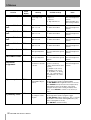
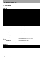
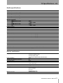
Menu reference
The following table provides a list of the menu
options available on the X-9, together with the
parameters available and their meaning.
In this table, default (factory) settings are marked
with a *.
See “Menus” on page 17 for details of how to use the
menu system.
1
2
3
4
6
7
5
ABCDEFGHI J KL MNOPQRSTUVWXYZ
ABcDEFGHIJKLMNOPQRSTUVWXYZ
0123456789- _+
0123456789-
_
+

5 Menus
18 TASCAM X-9 Owner’s Manual
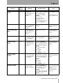
Function
Menu
display
Meaning Available settings Notes
Headphone EQ
01HP
Sets headphone EQ to
normal, high or low
boost
nOr
* (no EQ)
H
High boost
L
Low boost
HL
High and low boost
Can be performed on
both left and right menu
systems.
Takes immediate effect
before being confirmed.
Program 1 fader
start
02F1
Sets fader start for pro-
gram 1 on or off
OFF
* Fader start disabled
On
Fader start enabled
Can be performed on
both left and right menu
systems.
Program 2 fader
start
03F2
Sets fader start for pro-
gram 2 on or off
OFF
* Fader start disabled
On
Fader start enabled
Can be performed on
both left and right menu
systems.
Program 3 fader
start
04F3
Sets fader start for pro-
gram 3 on or off
OFF
* Fader start disabled
On
Fader start enabled
Can be performed on
both left and right menu
systems.
Program 4 fader
start
05F4
Sets fader start for pro-
gram 4 on or off
OFF
* Fader start disabled
On
Fader start enabled
Can be performed on
both left and right menu
systems.
Cross-fader A start
6cFA
Sets the cross-fader to
start signal A playback
OFF
Fader start disabled
On
* Cross-fader starts signal A
playback
Can be performed on
both left and right menu
systems.
Cross-fader B start
7cFb
Sets the cross-fader to
start signal B playback
OFF
Fader start disabled
On
* Cross-fader starts signal B
playback
Can be performed on
both left and right menu
systems.
Footswitch
assignment
08Ft
Sets the function of the
footswitches connected
to the X-9.
EF
* links to internal effects
(1=effect 1, 2=effect 2)
E
links to external effects (1& 2=
external)
S1
Sampler 1 (1=in, 2=out)
S2
Sampler 2 (1=in, 2=out)
CF
Crossfader (
1
on, hard A
side,
1
off, current position;
2
on, hard B side,
2
off, current
position)
Can be performed on
both left and right menu
systems.
EQ memory store
09EM
Stores currently-
selected EQ settings to
memory.
Use the left menu system for programs 1 and 3.
Use the right menu system for programs 2 and 4.
The
EQ MEMO
indicator lights when
09EM
is selected
When
ENTER
is first pressed, the lowest empty memory
bank number is shown. Use the dial to select a bank.
If the bank already contains a setting, the display shows
SURE
. Press
ENTER
to overwrite, or any other key to
cancel.
EQ memory recall
10Er
Recalls stored EQ mem-
ory settings to current
program.
Use the left menu system for programs 1 and 3.
Use the right menu system for programs 2 and 4.
The
EQ RECALL
indicator lights when
10Er
is selected
Use the dial to select a bank containing EQ memory (only
banks containing data are shown).
Press
ENTER
to recall the memory.

5 Menus
TASCAM X-9 Owner’s Manual 19
Program EQ Q
values
11
_
E
Sets the Q value for the
EQ bands of the
selected program (see
“EQ Q setting” on
page 28)
After pressing
ENTER
to
select the menu, use the dial to
select the band (
H
=high,
M
*=mid,
L
=low) and press
ENTER
.
A
low value of Q
nOr
Normal value of Q
B
high value of Q
Value changes as selection is
made. Press
ENTER
to con-
firm.
Use the left menu sys-
tem for programs 1 and
3.
Use the right menu sys-
tem for programs 2 and
4.
Meter release time
12Mr
Sets the meter release
time (see “Adjusting the
output volume” on
page 16).
nor
* Normal
SLO
Slow
Can be performed on
both left and right menu
systems.
Meter peak hold
time
13MP
Sets the meter peak
hold time (“Adjusting the
output volume” on
page 16)
All values are in seconds
OFF
0.5
1.0
*
2.0
Can be performed on
both left and right menu
systems.
Digital out
14dI
Sets whether the signal
from the digital output is
pre- or post master
fader
nOr
* Post-fader signal
rEc
Pre-fader signal
Can be performed on
both left and right menu
systems.
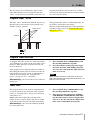
Program fader
curve
15Fc
Sets the fader curve as
described and shown in
“Program fader “curve””
on page 21.
After pressing
ENTER
to
select the menu, use the dial to
select the program fader to be
set (
1
,
2
,
3
or
4
) and press
ENTER
.
Select from the following:
A1
–6 dB
nOr
* –12 dB
A2
–24 dB
Press
ENTER
to confirm.
Can be performed on
both left and right menu
systems.
Program fader
reverse
16Fr
Sets the fader direction
to reverse as described
in “Program fader direc-
tion” on page 21.
After pressing
ENTER
to
select the menu, use the dial to
select the program fader to be
set (
1
,
2
,
3
or
4
) and press
ENTER
.
Select:
NOr
* Normal
rEV
Reverse
Press
ENTER
to confirm.
Can be performed on
both left and right menu
systems.
Sampler tempo
17St
Sets the sampler play-
back pitch for either
sampler 1 or sampler 2.
After pressing
ENTER
to
select the menu, use the dial to
select the sampler to be set
(
S1
*, or
S2
) and press
ENTER
.
Use the dial to select the value
(from -
100
to
100
) and press
ENTER
to confirm.
Can be performed on
both left and right menu
systems.
When sampler data is
erased, the value is
reset to 0%.
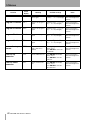
Function
Menu
display
Meaning Available settings Notes

5 Menus
20 TASCAM X-9 Owner’s Manual
Mic balance
18bM
Balances the micro-
phone signal
(hard left)
L9
to
L1
,
nor
(center) ,
r1
to
r9
(hard right)
Can be performed on
both left and right menu
systems.
Program 1 balance
19b1
Balances the program 1
signal
(hard left)
L9
to
L1
,
c0
(cen-
ter) ,
r1
to
r9
(hard right)
Can be performed on
both left and right menu
systems.
Program 2 balance
20b2
Balances the program 2
signal
(hard left)
L9
to
L1
,
c0
(cen-
ter) ,
r1
to
r9
(hard right)
Can be performed on
both left and right menu
systems.
Program 3 balance
21b3
Balances the program 3
signal
(hard left)
L9
to
L1
,
c0
(cen-
ter) ,
r1
to
r9
(hard right)
Can be performed on
both left and right menu
systems.
Program 4 balance
22b4
Balances the program 4
signal
(hard left)
L9
to
L1
,
c0
(cen-
ter) ,
r1
to
r9
(hard right)
Can be performed on
both left and right menu
systems.
Restore factory
presets
23FA
Restore all menu set-
tings to their factory
defaults.
Press
ENTER
. The display
shows
SURE
.
Press
ENTER
to restore fac-
tory defaults.
Can be performed on
both left and right menu
systems.
Clear all EQ
memories
24AC
Clears all EQ memories
Press
ENTER
. The display
shows
SURE
.
Press
ENTER
to clear the
memories.
Can be performed on
both left and right menu
systems.
Clear all effect
memories
25Ec
Clears all effect memo-
ries
Press
ENTER
. The display
shows
SURE
.
Press
ENTER
to clear the
effect memories.
Can be performed on
both left and right menu
systems.
Function
Menu
display
Meaning Available settings Notes
Page is loading ...
Page is loading ...
Page is loading ...
Page is loading ...
Page is loading ...
Page is loading ...
Page is loading ...
Page is loading ...
Page is loading ...
Page is loading ...
Page is loading ...
Page is loading ...
Page is loading ...
Page is loading ...
Page is loading ...
Page is loading ...
-
 1
1
-
 2
2
-
 3
3
-
 4
4
-
 5
5
-
 6
6
-
 7
7
-
 8
8
-
 9
9
-
 10
10
-
 11
11
-
 12
12
-
 13
13
-
 14
14
-
 15
15
-
 16
16
-
 17
17
-
 18
18
-
 19
19
-
 20
20
-
 21
21
-
 22
22
-
 23
23
-
 24
24
-
 25
25
-
 26
26
-
 27
27
-
 28
28
-
 29
29
-
 30
30
-
 31
31
-
 32
32
-
 33
33
-
 34
34
-
 35
35
-
 36
36


Ask a question and I''ll find the answer in the document
Finding information in a document is now easier with AI
Other documents
-
Tascam X-17 User manual
-
Rane MP 24 User manual
-
Pioneer DJM-909 User manual
-
-
SoundCraft 1601 User manual
-
Allen-Heath Xone 92 Pro 6 Channel DJ Mixer User manual
-
-
-
ALLEN & HEATH XONE:62 User guide
-