Page is loading ...

1
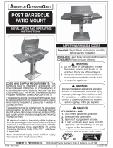
IMPORTANT: READ THESE INSTRUCTIONS CAREFULLY BEFORE STARTING INSTALLATION OR USE.
STAND-ALONE OUTDOOR
GAS GRILLS
DANGER:
IF YOU SMELL GAS:
1. Shut off the gas to the appliance.
2. Extinguish any open fl ame.
3. Open lid.
4. If odor continues, keep away from the
appliance and immediately call your
gas supplier or the fi re department.
WARNING:
1. Do not store or use gasoline or other
fl ammable vapors and liquids in the
vicinity of this or any other appliance.
2. An LP cylinder not connected for use
shall not be stored in the vicinity of this
or any other appliance.
CODE AND SUPPLY REQUIREMENTS: This grill
must be installed in accordance with local codes
and ordinances, or, in the absence of local codes,
with either the latest National Fuel Gas Code
(ANSI Z223.1/NFPA 54), and Natural Gas and
Propane Storage and Handling Installation Code
(CSA-B149.1).
This appliance and its dedicated manual shutoff
valve must be disconnected from the gas-supply
piping system when testing the system at pressures
in excess of ½ psig (3.5 kPa).
This appliance must be isolated from the gas-supply
piping system by closing its dedicated manual
shutoff valve during any pressure testing of the gas-
supply system at pressures up to and including ½
psig (3.5 kPa).
All electrical outlets in the vicinity of the grill must
be properly grounded in accordance with local
codes, or, in the absence of local codes, with the
National Electrical Code, ANSI/NFPA 70, or the
Canadian Electrical Code, CSA C22.1, whichever
is applicable.
Keep all electrical-supply cords and fuel-supply
hoses away from any heated surface.
Robert H. Peterson Co. • 14724 East Proctor Avenue • City of Industry, CA 91746
WARNING:
Improper installation, adjustment, alteration,
service, or maintenance can cause injury
or property damage. For proper installation,
refer to the installation instructions. For
assistance or additional information,
consult a qualifi ed professional installer,
service agency, or the gas supplier.
INSTALLATION
INSTRUCTIONS AND
OWNER’S MANUAL
INSTALLER: Leave these instructions with consumer.
CONSUMER: Retain for future reference.
SAFETY AND WARNING CODES
Proper operation of your grill
requires prompt and periodic
maintenance. See the CARE &
CLEANING section for details.
Certifi ed to: ANSI Z21.58b-2012
CSA 1.6b-2012
11-093
REV 0 - 1406030710
L-C2-428
C430s & C540s
C430s shown

3
CONTENTS
REV 0 - 1406030710
L-C2-428
4 REPLACEMENT PARTS LIST
6 GRILL NOTES PAGE
7 GRILL MAINTENANCE AND SAFETY INFORMATION
8 STAND-ALONE GRILL DIMENSIONS TABLE
8 MODEL SPECIFICATIONS TABLE
9 INSTALLATION REQUIREMENTS
10 ENSURING PROPER COMBUSTION AIR AND COOLING AIRFLOW
10 EXHAUST REMOVAL
11 LOCATION PREPARATION
11 WHEELS AND CASTERS
11 CONNECTING THE GAS SUPPLY
11 INSTALLING THE STAND-ALONE UNIT
13 SAFE USE & MAINTENANCE OF PROPANE GAS CYLINDERS
14 IDENTIFICATION OF GRILL CONTROLS
15 LIGHTING (IGNITION) INSTRUCTIONS
15 SHUTTING OFF THE UNIT
17 RIGID SHELF INSTALLATION
18 GRILLING TIPS
19 ACCESSORIES
19 THE WARMING RACK
20 FIRE MAGIC
®
DRIP TRAY
21 CARE & CLEANING
22 REGULATOR CONVERSION
22 GAS ORIFICE CONVERSION
22 CONVERTING THE GAS TYPE
23 BURNER AIR SHUTTER ADJUSTMENT
24 GRILL NOTES PAGE
25 TROUBLESHOOTING
26 WARRANTY

5
REPLACEMENT PARTS LIST (cont.)
REV 0 - 1406030710
L-C2-428
C430s C540s
Item Description Part No. Qty. Part No. Qty.
1.
Stainless cooking grid (set of 2 or 3) 3542-S-2 1 3543-S-3 1
2.
Flavor grid (set of 2 or 3) 3063-S-2 1 3064-S-3 1
3.
Main burner 3042-60 2 3042-60 3
4.
Oven lid 23729-54 1 23733-54 1
5.
Warming rack* 3672S-M 1 3673S-M 1
6.
Grid lifter 3519 1 3519 1
7.
Convertible regulator PR-4 1 PR-4 1
8.
Valve manifold 24130-28 1 24170-28 1
9.
Control panel 24130-36 1 24170-36 1
10.
Large knob 3015 2 3015 3
11.
Thermometer † 23305 1 23305 1
12.
Ignitor battery holder assy (9v) 24180-38 1 24180-38 1
13.
Drip tray 3084 1 3084 1
14.
Drip tray liner (set of 4) 3557 1 3557 1
15.
Wire harness assembly † 24177-24 1 24177-24 1
16.
Rigid shelf 24-C-01 2 24-C-01 2
17.
Door (left) 24330-29L 1 24370-29L 1
18.
Door (right) 24330-29R 1 24370-29R 1
19.
Caster kit (set of 4) 24-C-35 1 24-C-35 1
20.
Electrode & collector box assy † 3199-45 2 3199-45 3
21.
Ignitor module 3199-44 1 3199-46 1
22.
Natural gas orifi ce(s) † 3001-44-2 1 3001-44-3 1
23.
Propane gas orifi ce(s) † 3001-55-2 1 3001-55-3 1
24.
Propane regulator / hose assy. † 5110-07 1 5110-07 1
or
Natural Gas QD hose † 5110-03 1 5110-03 1
25.
Fire Magic
®
cookbook † 3595 1 3595 1
* If equipped
† Not shown

6
REV 0 - 1406030710
L-C2-428
GRILL NOTES PAGE
Please use this page to record any information about your grill that you may want to have at hand.

7
1. The outdoor grill and surrounding area MUST
remain clear of fl ammable substances such as
gasoline, yard debris, wood, etc.
2. The airfl ow through the vent space located below
the control panel must remain unobstructed.
3. When using propane gas:
a. The required ventilation openings in the
enclosure must be clear of debris.
b. The propane cylinder, regulator, and rubber
hose must be in a location not subject to
temperature above 125° F (51° C).
4. The fl ames on each burner burn evenly along
the entire burner with a steady fl ame (mostly
blue). If burner fl ames are not normal, check
and clean the orifi ce and burner/venturi tubes for
insects and insect nests. A clogged tube can
lead to a fi re beneath the grill. A proper fl ame
pattern will ensure safe operation and optimal
performance. Adjust the air shutter as needed
(see AIR SHUTTER ADJUSTMENT).
5. The in-line gas valve or gas cylinder valve must
always be shut OFF when the grill is not in
use.
6. The drip collector holes must be clear and
unobstructed. Excessive grease deposits can
result in a grease fi re.
WARNING: NEVER cover the entire cooking or grill surface with griddles or pans. Overheating will occur, and
burners will not perform properly when combustion heat is trapped below the cooking surface.
CAUTION: NEVER spray water on a hot gas unit.
GRILL MAINTENANCE AND SAFETY INFORMATION
The grill serial identifi cation number is located on the underside of the drip tray handle. It
is recommended that the drip tray fi rst be removed and cleaned / emptied of its contents,
then turned over to view.
REV 0 - 1406030710
L-C2-428

8
MODEL SPECIFICATIONS TABLE
REV 0 - 1406030710
L-C2-428
Model
Height Width Depth
Floor to top
(with oven)
Floor to top
of shelf
(C)
Left to right Front to back
Cart base
(D)
Shelf to shelf
(E)
Cart base
(F)
Maximum
outer
(G)
Open (A)
Closed
(B)
A430s
57" 50" 36
1
/2" 26
1
/2" 51
1
/2" 22" 24
3
/4"
A540s
57" 50" 36
1
/2" 33" 58" 22" 24
3
/4"
STAND-ALONE GRILL DIMENSIONS TABLE
G
C
F
E
B
D
A

9
INSTALLATION REQUIREMENTS
This grill is designed for outdoor use only. DO NOT use this grill
inside a building, garage, enclosed area, or under an unprotected
overhead combustible construction. See the EXHAUST REMOVAL
section on the following page for details on installing under a patio
roof. DO NOT use this grill in or on a recreational vehicle or boat.
Important: The grill is not insulated. Refer to the information
below to ensure all required clearances are met.
The grill must have a minimum clearance of 18" from
combustible materials/items AT ALL TIMES.
For the minimum clearances between the grill and any side or rear
walls, your setup must fall within one (or more) of the following:
A. Clearance between grill and combustible wall
• The grill must have a minimum of 18" right, left, and rear
clearance from any combustible wall (see Fig. 9-1).
B. Clearance between grill and strictly non-combustible wall
(i.e. brick wall, see Fig. 9-2)
• The grill must have a minimum of 4" right, left, and rear
clearance from any non-combustible wall.
(To allow for proper ventilation and prevent dangerous
overheating.)
MODEL SPECIFICATIONS (cont.)
REV 0 - 1406030710
L-C2-428
MODEL SPECIFICATIONS TABLE
Table 1 C430s C540s
Main burner BTU
N/P orifi ce drill size
20,000 x 2
#44/#55
20,000 x 3
#44/#55
Fig. 9-1 Clearance 'A' Diagram
Combustible
Min.
18"
(Clearance required for
right, left, and rear)
Fig. 9-2 Clearance 'B' Diagram
Non-combustible
Min.
4"
(Clearance required for
right, left, and rear)

10
INSTALLATION REQUIREMENTS (cont.)
The control panel MUST remain removable for
servicing and air shutter adjustment (see PARTS
LIST).
ENSURING PROPER COMBUSTION AIR AND
COOLING AIRFLOW
Proper airfl ow (Fig. 10-1) MUST be maintained for
the grill to perform as it was designed. If airfl ow
is blocked, overheating and poor combustion will
result. Do not block the 1" (2.5 cm) front air inlet
along the bottom of the control panel or more
than 75% of the cooking grid surface with pans
or griddles.
Note: The 1" (2.5 cm) front air space also allows
access to the drip tray.
EXHAUST REMOVAL
If installed or used under a patio roof, the cooking
grid area must be fully covered by an exhaust hood
with a vent. An exhaust fan with a rating of 1,000
CFM (cubic feet per minute) (472 liters per second)
or more may be necessary to effectively remove
smoke and other cooking by-products from the area
under the hood.
Fire Magic Vent Hoods are available
to meet this requirement.
This outdoor grill must not
be used under unprotected overhead combustible
construction. THIS UNIT MUST NOT BE LOCATED
IN A FULLY ENCLOSED AREA OF ANY KIND.
CAUTION: Wind blowing into or across the rear
oven lid vent (Fig. 10-2) can cause
poor performance and/or dangerous
overheating. Orient the grill so that the
prevailing wind blows toward the front
of the grill (Fig. 10-3).
GAS SUPPLY AND MANIFOLD PRESSURES:
For natural gas - normal 7" (17.78 cm) water column
(w.c.), minimum 5" (12.7 cm), maximum 10
1
/
2
" (26.7
cm). For propane gas - normal 11" w.c., minimum 10"
(25.4 cm), maximum 13" (33 cm).
REV 0 - 1406030710
L-C2-428
Fig. 10-3
CORRECT
PLACE GRILL SO PREVAILING
WIND BLOWS TOWARD FRONT
OF GRILL
YOU MUST PROTECT
REAR OVEN VENT FROM
PREVAILING WIND
Rear oven lid vent
INCORRECT
Fig. 10-2
Fig. 10-1 - Ventilation diagram

11
LOCATION PREPARATION
Prepare a fl at, level surface capable of supporting
the weight of the stand-alone grill and convenient to
the gas supply if connecting to a gas line.
WHEELS AND CASTERS
To lock a caster press down on the left lever until it
stops and the caster will not turn. To unlock, press
down on the right lever.
INSTALLING THE STAND-ALONE UNIT
CONNECTING THE GAS SUPPLY
For connecting a propane unit to a portable
propane tank, read the safety warnings and
follow the instructions in the section SAFE USE
AND MAINTENANCE OF PROPANE GAS
CYLINDERS.
For household propane or natural gas units:
a. Turn OFF the gas supply at the source. The
quick disconnect hose is pre-installed on the
valve manifold at the manufacturer. Run the
hose through the hole in the bottom rear of the
stand-alone unit, to the gas supply. Connect
the
1
/
2
" NPT socket at the end of the hose to
the gas supply. Use pipe joint compound that is
resistant to all gasses on the male pipe fi tting
and tighten securely. DO NOT use pipe joint
compound to connect the fl are fi ttings.
c. Turn all burner valves to the OFF position. Turn
the gas supply on. Then carefully check all gas
connections for leaks with a brush and soapy
water before lighting. NEVER USE A MATCH
OR OPEN FLAME TO TEST FOR LEAKS.
REV 0 - 1406030710
L-C2-428
Fig. 11-1
LOCK
UNLOCK

13
U
L
Fig. 13-1 Type I Acme thread quick coupler
Pressure
relief
valve
QCC
Type 1
valve
Brass Acme
thread fi tting
Liquid level
indicator
(optional)
Hand nut with Acme
thread
Regulator
Vent
Hose
Hand wheel
The use of pliers or a wrench should not be necessary. Only
cylinders marked “propane” may be used.
To disconnect: Turn the hand nut counterclockwise until
detached (Fig. 13-1).
Important: Before using the unit, and after each time the
cylinder is removed and reattached, check
the hose for wear (see a.) and check all
connections for leaks. Turn off the unit valves
and open the main cylinder valve, then check
connections with soapy water. Repair any
leaks before lighting the unit.
CAUTION: Always turn the propane cylinder main valve
off after each use, and before moving the unit
and cylinder or disconnecting the coupling.
This valve must remain closed and the
cylinder disconnected while the appliance
is not in use, even though the gas fl ow is
stopped by a safety feature when the coupler
is disconnected.
Carefully inspect the hose assembly each time before the
gas is turned on. A cracked or frayed hose must be replaced
immediately.
If the appliance is stored indoors, the cylinder must be
disconnected and removed. Disconnected
cylinders must be
stored outdoors, out of the reach of children, with threaded
valve plugs tightly installed, and must not be stored in a
building, garage, or any other enclosed area.
FOR YOUR SAFETY
a. DO NOT store a spare propane-gas cylinder under or
near this appliance.
b. NEVER fi ll the cylinder beyond 80-percent full.
c. IF THE INFORMATION IN a. AND b. IS NOT FOLLOWED
EXACTLY, A FIRE CAUSING DEATH OR SERIOUS
INJURY MAY OCCUR.
IMPORTANT FOR YOUR SAFETY
READ AND FOLLOW ALL WARNINGS PROVIDED WITH THE PROPANE-GAS CYLINDER.
When operating this appliance with a propane-gas cylinder, these instructions and warnings MUST be observed.
FAILURE TO DO SO MAY RESULT IN A SERIOUS FIRE OR EXPLOSION.
CYLINDER/CONNECTOR REQUIREMENTS
a. Propane-gas cylinders, valves, and hoses must be
maintained in good condition and must be replaced if
there is visible damage to either the cylinder or valve. If the
hose is cut or shows excessive abrasion or wear, it must
be replaced before using the gas appliance (see e.).
b. This unit, when used with a cylinder, should be connected
to a standard 5-gallon (20 lb.) propane-gas cylinder
equipped with an OPD (Overfi ll Prevention Device).
The OPD has been required on all cylinders sold since
October 1,1998, to prevent overfi lling.
c. Cylinder dimensions should be approximately 12" (30.5
cm) in diameter and 18" (45.7 cm) high. Cylinders must
be constructed and marked in accordance with the
Specifi cations for Propane Gas Cylinders of the U.S.
Department of Transportation (D.O.T.) or the National
Standard of Canada, CAN/CSA-B339, Cylinders,
Spheres, and Tubes for Transportation of Dangerous
Goods.
d. The cylinder used must include a collar to protect the
cylinder valve, and the cylinder supply system must be
arranged for vapor withdrawal.
e. The pressure regulator and hose assembly (Fig. 13-1)
supplied with this outdoor gas appliance (L.P. models
only) must be used. Original and replacement pressure
regulator and hose assemblies must be those specifi ed
by the manufacturer for connection with a cylinder
connecting device identifi ed as Type I by the ANSI Z
21.58-2005/CGA 1.6-2005 (see PARTS LIST for ordering
information).
f. The propane-gas cylinder valve must be equipped with a
cylinder connection coupling device, described as Type I
in the standard defi ned in paragraph e. above. This device
is commonly described as an Acme thread quick coupler.
g. If the propane-gas cylinder comes with a dust plug, place
the dust cap on the cylinder valve outlet whenever the
cylinder is not in use.
QUICK COUPLER OPERATION
To connect the regulator/hose assembly to the propane-
gas cylinder valve fi tting: Press the hand nut on the regulator
over the Acme thread fi tting on the cylinder valve. Turn the hand
nut clockwise to engage the threads and tighten until snug.
SECURING THE PROPANE-GAS CYLINDER
1. Set the propane-gas
cylinder into the support
sleeve.
3. Tighten the thumb screws to secure
the cylinder.
2. Follow the instructions
above to connect supply.
Tighten
Fig. 13-2
Fig. 13-3 Fig. 13-4
Connect
to supply
SAFE USE & MAINTENANCE OF PROPANE GAS CYLINDERS

14
IDENTIFICATION OF GRILL CONTROLS
Fig. 14-1
Left
main burner
control knob
Right
main burner
control knob
Center main burner
control knob
Fig. 14-2
Left
main burner
control knob
Right
main burner
control knob
Drip
tray
Drip
Tray
C430 controls
C540 controls
Control panel
screw(s)
Control panel
screw(s)
Battery box
Battery box
To remove the control panel:
•
Turn off the gas shutoff valve.
• Pull off the control knobs. Unscrew and remove the control panel
screws and washers.
• Lift the control panel up and outward, allowing it to rest on the
internal chain(s).
Important: During reinstallation;
prior to opening the gas shutoff
valve, be sure the control knobs are in the OFF position.

15
SHUTTING OFF THE UNIT
To shut off the unit, depress each valve control knob
and, and while pressing turn it clockwise to the OFF
position.
Always close the valve from the gas supply after each
use of the unit.
ELECTRONIC LIGHTING
Note: Electronic lighting requires an installed 9-volt
battery with a good charge.
1. Open lid(s) or remove cover(s) from burner(s) to be lit.
2. Turn all gas control knob(s) to their OFF position(s).
3. Turn on the gas at its source.
Note: DO NOT
turn on more
than one valve at
a time for either
electronic or
manual lighting.
4. Depress the desired control knob for 5 seconds,
then, while pressing turn it counterclockwise to the
HI LIGHT position. Once the burner lights, release
the knob.
CAUTION: If a burner does not light within fi ve (5)
seconds of turning on the control knob,
depress the knob and turn it to the OFF
position. WAIT FIVE (5) MINUTES
before repeating step 4. If you smell
gas, follow the instructions on the cover
of this manual. If the burners still do not
light after several attempts, refer to the
instructions for manual lighting.
5. Repeat step 4 for each additional burner to be lit.
WHEN USING A PORTABLE PROPANE TANK
Propane tanks are equipped with a safety shutdown
device that may cause low or no gas pressure/fl ame
at the burners if operating and lighting instructions
are not followed exactly (See important note in the
TROUBLESHOOTING section for more details.)
MANUAL LIGHTING
CAUTION: Always wait fi ve (5) minutes for gas to
clear after any unsuccessful lighting
attempt.
1. Follow steps 1 through 3 (left).
2. Insert either a burning long-barrel butane lighter or
a burning long-stem match through the cooking grid
opening to the top of the lighting tube. (Fig. 15-2).
For backburners, hold the flame
against the surface of the backburner.
For sideburners, hold the fl ame against the burner.
3. While holding the match or lighter fl ame at the top
of the lighting tube or next to the burner (sideburner
and backburner only), depress the desired control
knob and while pressing turn it counterclockwise to
the HI LIGHT position. Remove the lighter or match
when the burner lights, and release the control
knob.
4. If the burner does not light, immediately depress
the knob and turn the valve to OFF. WAIT FIVE
(5) MINUTES before repeating steps 2 through 4
of the MANUAL LIGHTING instructions.
Read all instructions before lighting, and follow these instructions each time you light the unit.
Fig. 15-2 - Manual lighting
Lighter
Lighting
tube
Fig. 15-1 - Control knob
OFF
HI
LIGHT
LOW
TO
TURN OFF
TO TURN ON
Read setting
here
HIGH to
LIGHT
Read setting here
(OFF position shown)
To Turn OFF
To Turn ON
Use
HI (high)
to light
Press
knob in
to turn
REPLACING IGNITOR BATTERIES
To replace the 9V battery powering the ignitors, pull out
the battery holder located on the outside of the control
panel. Remove the old battery and replace it connecting
the new battery. Replace the drawer (see Fig. 15-3).
Fig. 15-3
2. Insert either a burning long-barrel butane lighter, a
burning long-stem match, or a burning match held
by a wire extension holder through the cooking grid
opening to the top of the burner (Fig. 15-2).
3. While holding the match or lighter fl ame at the top
of the burner, depress the control knob and while
pressing turn it counterclockwise to the HI LIGHT
position. Remove the lighter or match when the
burner lights, and release the control knob.
4. If the burner does not light, immediately depress
the knob and turn the valve to OFF. WAIT FIVE
(5) MINUTES before repeating steps 2 through 4
of the MANUAL LIGHTING instructions.
LIGHTING (IGNITION) INSTRUCTIONS

17
Shelf support screws
View from under right shelf
This barbecue comes with two (2) rigid shelves that
must be attached. These can be attached using the
four support screws provided and a Phillips-head
screw driver.
1.
Hold the shelf inverted so that one of the corner
holes in the shelf lines up with the appropriate
upper screw hole in the barbecue.
2. Insert the screw, but do not tighten all the way so
that the shelf can be easily rotated around the fi rst
screw.
3. Line up the second corner hole in the shelf with
the remaining upper screw hole in the barbecue.
Insert a screw and tighten.
Note: You may lift the edge of the shelf upward
to gain better access during much of the
tightening of this screw.
4. Finally, insert the bottom screws on the left and right
side of the shelf and securely tighten all screws.
To detach, reverse the process above.
RIGID SHELF INSTALLATION
This barbecue comes with one rigid shelf that must
be attached. It can be attached using the four support
screws provided and a Phillips-head screwdriver.
1. Insert the top two screws into the side of the
barbecue and screw them in about half way.
2. Line up the larger, bottom portion of the two
keyhole openings with the two top screws and fi t
the two keyhole openings over the two screws.
With the shelf pushed all the way against the
side of the barbecue, lower the shelf so that the
screws lock into the narrower, upper portions of
the keyholes.
Note: The shelf will now stay in place on it’s
own.
3. Insert the bottom two screws into their holes and
tighten them all the way.
4. Finally, tighten the upper two screws,
completely.
To detach, reverse the process above.
This barbecue comes with two rigid shelves that must be
attached. These can be attached using the four support
screws provided and a Phillips-head screwdriver.

18
The art of grilling involves learning the nuances of your
grill and knowing how various cuts of meat and other
foods cook on it under different settings and conditions.
Each grill will be unique due to its configuration
and how it is positioned or installed. This section
contains information about how Fire Magic grills were
engineered, which will help you in learning how your
grill responds to the way you use it.
GRILL HEAT DISTRIBUTION - MAIN BURNERS
The heat level at each part of the grill has been
engineered for specifi c purposes. Knowing the heat
distribution for each burner will allow you the best
possible food positioning when grilling.
CAUTION: Even the coolest part of the grill is too
hot to be touched during operation of
the grill.
The front of the grill is designed, for safety reasons,
to be the coolest part of the grill. If you look directly
down on the grill top, while it is off and cool, you can
see this portion of the grill, where the front end of each
burner stops and the slope of the inner grill fi re wall
begins. This area also loses heat most rapidly when
the oven lid is opened (see Fig. 18-2).
From the front of the grill moving toward the back, the
heat rises gradually until just above the burner’s front
edge, where it rises rapidly to a fairly even temperature
refl ected by the thermometer. The heat continues to
rise gradually until it reaches a maximum directly
above the place where the two lobes of each burner
connect (see Fig. 18-2). From there to the back of
the grill, heat diminishes moderately. This supports
the desired temperature for the warming rack and
prevents heat from becoming excessive at the back
fi re wall of the grill.
WIND CONSIDERATIONS
Wind direction can have an effect on the grill,
especially with the oven open. For maximum stability
and convenience, position the grill so that the oven
opens toward any prevailing wind (Fig. 18-1).
Fig. 18-1
Orient barbecue so prevailing
wind blows in this direction
Fig. 18-2
Medium heat
Medium heat
High heat
Low heat
GRILLING TIPS

19
THE DRIP TRAY
The drip collection system allows you to brush or scrape
excess dried residue from the grilling area directly into
the drip tray (see PARTS LIST for drip tray location).
THE COOKING GRID LIFTER
Hold the grid lifter by gripping the center section with the
prongs pointing down (use an oven mitt or heavy glove
if the grill is hot). Insert the notched end of the grid lifter
into the cooking grid, in front of the midway point (front
to back; Fig. 19-3), and central (left to right; Fig. 19-4).
Twist the grill lifter (clockwise or counterclockwise) so
the handle is parallel to the grill rods. This “seats” the
spiked end of the grid lifter between two rods, enabling
you to safely lift out the grid. Lift slowly and adjust the
grid lifter, if necessary, for balance.
Placement of the grid lifter in cooking grid
Fig. 19-3
Fig. 19-4
GRILL BRUSH (optional)
Purchase a Fire Magic
®
stainless-steel grill brush (sold
separately) to keep your grill cleaner. It comes with
scraper for large particles and a replaceable head with
brass bristles for overall cleaning.
Grill brush with replacement head
Fig. 19-1
WARMING RACK (if equipped)
The warming rack (Fig. 19-2) is packed separately.
To install the warming rack, lift the front of the rack up
slightly and insert the rack hangers into the two holes
in the back of the inner oven hood. Then lower the front
of the rack into a level position to lock the rack in place.
To remove the warming rack, lift up on the front of the
rack until the rack hangers pull free from their supporting
holes.
Note: Removing the warming rack before using the
rotisserie will leave more clearance for the
meat being cooked. (if applicable)
Fig. 19-2 Warming rack in place inside oven
Flavor grid
THE FLAVOR GRID(S)
Place each fl avor grid directly over a burner. The solid
areas of the grid should rest over the tabs found on the
burner. See Fig. 19-5. The slightly larger grids are
designed to be placed over the outside burners,
and the slightly smaller grid(s) are designed to be
placed over the interior burner(s).
Note: This allows heat from the burners to be evenly
distributed throughout the cooking area. The
fl avor grids heat and cool quickly, making the
grill very responsive to changes in heat from
the burners.
Fig. 19-5
ACCESSORIES

20
Drippings from grilling flow through specially
designed channels and collect in the drip tray . Check
the drip tray regularly and empty when required.
Your grill includes a pack of four (4) Fire Magic
®
drip tray liners (Fig. 20-1). For your convenience
in cleanup, place a liner into the drip tray before
grilling.
To fi t a liner into the drip tray, pull out the tray and
set it on a fl at, level surface. Place the liner in the
drip tray as shown in Fig. 20-2 and carefully insert
the tray back under the control panel.
Note: Be sure that the liner is properly placed into
the the drip tray. The front of the liner must fi t
under the drip tray's lighting instruction plate
(see 20-3 detail).
After each use, wait for the grill to cool and carefully
pull out the drip tray to check it. When a liner is
nearing full, carefully lift it out of the drip tray, lifting
with both hands to keep the tray level until it is safely
discarded. Then insert a new drip tray liner.
Order more drip tray liners through your local Fire
Magic
®
dealer.
Note: The foil tray liner is also useful for setting on
burners to cover them and catch drippings
directly during rotisserie only cooking.
Note: For models with match holders attached
inside the drip tray, place the match holder
off to one edge of the pan (Fig. 20-3). If
necessary, mold the foil liner around them
and the other features of the tray to create
enough clearance space to open and close
the tray without catching the liner.
Fig. 20-1
Be sure liner fi ts under lighting instruction plate
Pull out the drip tray and place liner
Fig. 20-2
Fig. 20-3
Note: There are easy to follow lighting instructions
etched onto the top of the drip tray handle.
FIRE MAGIC
®
DRIP TRAY

21
Fig. 21-1 - Wipe with grain
PROTECTING YOUR APPLIANCE FROM THE
WEATHER
An optional cover will protect your appliance when not
in use. (Allow to cool before covering.)
Please specify the model number and serial number
of your appliance when ordering a cover.
APPLIANCE MUST BE COMPLETELY COOL WHEN
CLEANING. DO NOT SPRAY ANY CLEANER OR
LIQUIDS ON THE APPLIANCE WHEN HOT.
The appliance must be cleaned as often as once a month
(depending on use) to prevent grease build-up and other
food deposits.
INTERIOR
THE BURNER PORTS MUST BE KEPT CLEAN TO
ENSURE PROPER IGNITION AND OPERATION.
Remove the burner (see orifi ce changing instructions)
and clean the ports and slots as required. (For Fire Magic
grills use Maintenance Kit part #MK-1.) Also inspect and
clean the burner inlet for insects and nests. A clogged
burner can lead to a fi re in the bottom of the appliance.
The inside of the appliance may be cleaned periodically
with oven cleaner if desired. Follow the oven cleaner
instructions for proper use.
Be careful not to get oven cleaner on the outside surface
of the appliance as it can permanently damage the fi nish.
EXTERIOR
Stainless steel surfaces when exposed to temperatures
produced by the grilling process will change color. The
stainless steel will change color from silver to brown
and blue. This can be removed by using stainless steel
cleaner.
Clean your appliance by fi rst using grill cleaner to remove
grease and dirt. Always wipe with the grain (See Fig.
21-1). Next, use stainless steel cleaner to restore the
stainless steel color (Note: not for mirror fi nish). Finish
by wiping your appliance down using polish wipes. To
clean any mirror fi nish (if applicable), use a quality
brand glass cleaner only, not any of the cleaners
mentioned above.
If your appliance is installed in a seaside (salt air) or
poolside (chlorine) location, it will be more susceptible
to corrosion and must be maintained/cleaned more
frequently. Do not store chemicals (such as chlorine or
fertilizer) near your stainless steel appliance.
Due to the nature of stainless steel, surface iron oxide
deposits may appear. Do not be alarmed – these deposits
are removable with stainless steel cleaner through prompt
and periodic maintenance. If not attended to promptly,
permanent pitting may occur.
By following these recommendations, you will enjoy the
beauty and convenience of your appliance for many years
to come.
IMPORTANT
IN THE EVENT OF A GREASE FIRE, IMMEDIATELY
SHUT OFF THE MAIN GAS VALVE TO THE GRILL.
KEEP THE LID OPEN AND ALLOW THE FIRE TO
EXTINGUISH ITSELF. A THOROUGH INSPECTION
BY A TRAINED SERVICE TECHNICIAN SHOULD
BE CONDUCTED BEFORE FUTURE USE OF YOUR
GRILL. THE SERVICE TECHNICIAN WILL CHECK
THE SYSTEM FOR GAS LEAKS AND WILL CHECK
ALL ELECTRICAL WIRING FOR DAMAGE. ALL GAS
LEAKS AND WIRING MUST BE REPAIRED PRIOR
TO FUTURE USE.
Wipe with grain
CARE & CLEANING

22
REGULATOR CONVERSION
The gas regulator, located behind the control panel, must
be set for the type of gas used to fuel the grill. To check
the regulator setting, remove the cap in the center of the
regulator (Fig. 22-1). Holding the cap vertical (see Fig.
22-2), the letters at the bottom of the plastic stalk indicate
the gas type for which the regulator is currently confi gured.
If the bottom of the regulator stalk does not indicate the
gas connected to the grill, remove the stalk from the cap,
invert, and replace into center of cap. Replace cap on the
regulator, screwing down until snug.
GAS ORIFICE CONVERSION
This Fire Magic
®
grill comes from the factory confi gured
for one type of gas as marked on the label behind the
control panel. When the grill is converted, this label
must be replaced or updated to identify the new gas.
Each burner has a brass orifi ce, which can be replaced
and must match the gas being used. When converting
the grill to a different gas, each burner’s orifi ce must be
replaced with the corresponding orifi ce for the new gas.
Natural-gas to propane-gas conversions using a
tank internal to a portable grill require installation of
a propane tank holder (not included) for safety and
compliance with the ANSI standards referenced on
the cover of this document. This tank holder must be
purchased separately from the manufacturer.
Consult Table 1 at the beginning of this document to
determine the proper orifi ce sizes for each burner.
It is critical to the operation of each burner that its orifi ce
be fully inserted into the center of its orifi ce opening.
WARNING
Hazardous overheating will occur if a natural-gas
orifi ce is used with propane gas.
CAUTION: Make sure the grill is at a safe
temperature and isolated from gas and
electrical supplies before beginning.
For your safety, exercise caution, and make sure you
have adequate hand protection, such as gloves, when
handling metal parts.
Required tools:
• Phillips-head screwdriver (#2 medium)
•
3
/
8
" hex nut driver (deep socket)
CHANGING THE MAIN BURNER ORIFICES
1. Remove the cooking
grid and fl avor grid from
above the burner you
are working on and set
them aside.
2. Slightly pinch and
remove the burner clip
found on the rear center
of the burner. Next lift
the rear of the burner
out of the anchor pegs
holes, move the burner toward the back of the grill
to clear the gas inlet, and set it aside (Fig. 22-3).
3. Use a
3
/
8
" hex nut driver to
remove the exposed orifice
(Fig. 22-4) and replace it
with the correct orifi ce for the
new gas. (See Table 1 at the
beginning of this document for
orifi ce sizes.)
4. Replace the burner by first
sliding the open cylindrical
end of the burner around the
orifi ce, enveloping it and centering on it, then lower
the back end anchor pegs into the anchor peg holes.
Then replace the burner clip.
Note: It is critical to the continued safe functioning
of the burner that the orifi ce is centered and
completely inside the burner gas conduit.
5. Replace the fl avor grid and then the cooking grid so
that the cutout section of the cooking grid is lined
up with the lighting tube.
Repeat these steps for each main burner.
Fig. 22-4
Orifi ce
CONVERTING THE GAS TYPE
Fig. 22-1
Fig. 22-2
Read gas
type here.
(LP shown)
Gas regulator
Note the cap on top.
Fig. 22-3

23
1. Follow the safety precautions and steps for
main burner removal
in the CHANGING
THE MAIN BURNER
ORIFICES section
(steps 1-2).
2. Adjust the air shutter
opening by loosening
the adjustment screw
with a screwdriver,
then turn the air
shutter to open or close it (see Fig. 23-2).
Too large an air shutter opening will allow too much
air into the burner, which will cause the fl ames fi rst
to shorten and then to appear to lift up off the ports.
For the bottom of the fl ames to move closer to the
ports, close the air shutter more.
If the air shutter opening is too small or closed, the
fl ames will present consistently orange tips and
become “lazy,” slowly undulating back and forth.
For propane gas, ideal settings tend to be just
slightly open. For natural gas, which generally
requires less primary air than propane, the main
burner air shutter may be nearly closed.
3. Adjust the air shutter opening and then replace
the burner.
4. Follow the lighting instructions in this manual to
light the burner.
5. Repeat steps 1-4 until the fl ames appear to
touch the burner ports, burning fairly steadily
and mostly blue (see Fig. 23-1).
6. Replace the burner, burner clip, fl avor grid,
and cooking grid (see CHANGNG THE MAIN
BURNER ORIFICE section, steps 4-5).
Repeat these steps for each main burner.
AIR SHUTTER ADJUSTMENT
Important: Air shutters are preset at the
factory based on the gas the grill is
built to burn. However, altitude or
other local conditions may require
air shutter adjustment for proper
combustion.
MAIN BURNER
Flames from a properly adjusted main burner with
no wind or breeze present will appear fairly steady,
consistent, and mostly blue. If the tip of a fl ame were
to turn orange, it should only do so briefl y and then
become blue again. The fl ames will appear to burn
while touching the burner ports (see Figure 23-1).
If the fl ames have orange in them and appear to
undulate slowly from side to side, or if some of them
appear to lift off the burner instead of touching it,
then adjust the air shutter, as instructed below.
CAUTION: Turn all burner control knobs to the
OFF position and turn off the gas
supply at the source before removing
or adjusting a burner.
WARNING
Wait for the burner to be cool or use heavily insulated
heat-resistant gloves when handling the burner.
Shutter Setting Flame Condition
Open too far
Flames shorten and
lift off the burner
Ideal setting
Blue fl ames just
touching burner
Closed too far
“Lazy” fl ames with
orange in them
BURNER AIR SHUTTER ADJUSTMENT
Fig. 23-1 - Flame appearance diagram
Flame off ports
Flame on ports
Fig. 23-2
Locking
screw
Air shutter

24
GRILL NOTES PAGE
Please use this page to record any information about your unit that you may want to have at hand.
/