Page is loading ...

Document No 50374-001 Page 1 of 7 Rev A 05/2016
1X Image Converter
P/N LBP2-UVIMG
with
Optional Beam Splitter
P/N LBP2-UVBS
Laser Beam Analyzer
For Windows 7
®
LBP2 Series

Document No 50374-001 Page 2 of 7 Rev A 05/2016
Warranty
Newport Corporation warrants that this product will be free from defects in material and
workmanship and will comply with Newport’s published specifications at the time of sale
for a period of one year from date of shipment. If found to be defective during the
warranty period, the product will either be repaired or replaced at Newport's option.
To exercise this warranty, write or call your local Newport office or representative, or
contact Newport headquarters in Irvine, California. You will be given prompt assistance
and return instructions. Send the product, freight prepaid, to the indicated service
facility. Repairs will be made and the instrument returned freight prepaid. Repaired
products are warranted for the remainder of the original warranty period or 90 days,
whichever first occurs.
Limitation of Warranty
The above warranties do not apply to products which have been repaired or modified
without Newport’s written approval, or products subjected to unusual physical, thermal
or electrical stress, improper installation, misuse, abuse, accident or negligence in use,
storage, transportation or handling. This warranty also does not apply to fuses, batteries,
or damage from battery leakage.
THIS WARRANTY IS IN LIEU OF ALL OTHER WARRANTIES, EXPRESSED OR
IMPLIED, INCLUDING ANY IMPLIED WARRANTY OF MERCHANTABILITY OR
FITNESS FOR A PARTICULAR USE. NEWPORT CORPORATION SHALL NOT
BE LIABLE FOR ANY INDIRECT, SPECIAL, OR CONSEQUENTIAL DAMAGES
RESULTING FROM THE PURCHASE OR USE OF ITS PRODUCTS.
First printing 2016
© 2016 by Newport Corporation, Irvine, CA. All rights reserved. No part of this
manual may be reproduced or copied without the prior written approval of Newport
Corporation.
This manual has been provided for information only and product specifications are
subject to change without notice. Any change will be reflected in future printings.
Newport Corporation
1791 Deere Avenue
Irvine, CA, 92606
USA

Document No 50374-001 Page 3 of 7 Rev A 05/2016
Technical Support Contacts
North America
Europe
Newport Corporation Service Dept.
1791 Deere Ave. Irvine, CA 92606
Telephone: (949) 253-1694
Telephone: (800) 222-6440 x31694
Newport/MICRO-CONTROLE S.A.
Zone Industrielle
45340 Beaune la Rolande, FRANCE
Telephone: (33) 02 38 40 51 56
Asia
Newport Opto-Electronics
Technologies (Wuxi) Co., Ltd
理波光电科技(无锡)有限公司
江苏省无锡市新区出口加工区
J3-8厂房 204028
Lot J3-8, Wuxi Export Processing Zone,
New District, Jiangsu China 204028
Telephone: +86-510-8113 2999
Fax: +86-510-8526 9050
Newport Corporation Calling Procedure
If there are any defects in material or workmanship or a failure to meet specifications, promptly
notify Newport's Returns Department by calling 1-800-222-6440 or by visiting our website at
www.newport.com/returns within the warranty period to obtain a Return Material
Authorization Number (RMA#). Return the product to Newport Corporation, freight prepaid,
clearly marked with the RMA# and we will either repair or replace it at our discretion. Newport
is not responsible for damage occurring in transit and is not obligated to accept products returned
without an RMA#.
E-mail: rm[email protected]
When calling Newport Corporation, please provide the customer care representative with the
following information:
Your Contact Information
Serial number or original order number
Description of problem (i.e., hardware or software)
To help our Technical Support Representatives diagnose your problem, please note the following
conditions:
Is the system used for manufacturing or research and development?
What was the state of the system right before the problem?
Have you seen this problem before? If so, how often?
Can the system continue to operate with this problem? Or is the system non-
operational?
Can you identify anything that was different before this problem occurred?

Document No 50374-001 Page 4 of 7 Rev A 05/2016
Notice
All rights to the product and any accompanying user guide(s) are reserved by Newport
Corporation.
Newport Corporation reserves the right to make improvements to the product described
in this user guide at any time and without prior notice.
While every precaution has been taken in the preparation of this guide, the publisher
and author assume no responsibility for errors, omissions, or any loss of data because of
said errors or omissions.
Personal computer hardware and component manufacturers, along with operating
system providers constantly revise their products and software upon which this product
is dependent. While Newport Corporation endeavors to maintain maximum compatibility
with a wide variety of personal computer configurations, Newport Corporation makes no
guarantee that any one brand or model of personal computer will be compatible with
any or all of the features contained in this application, either now or in the future.
Obtain the latest version of this user guide at the product page in www.newport.com

Document No 50374-001 Page 5 of 7 Rev A 05/2016
1X UV Image Converter (P/N LBP2-UVIMG)
With Optional Beam Splitter (P/N LBS2-UVBS)
User Notes
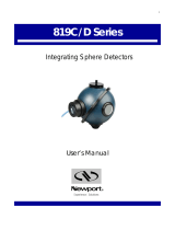
The 1X Image Converter is an attachment to a beam profiler camera that enables it to operate
better in the UV from 157nm to 360nm. The 1X Image Converter operates as follows (see
diagram): The UV beam falls on the fluorescent plate which fluoresces in the visible. The
fluorescent plate is transparent to the visible light but not the UV
(1)
. Thus only the bright
fluorescing image is seen by the camera. The optical system images the beam plane onto the
CCD of the camera, keeping the image size the same as the object size. Replaceable ND filters
are chosen by the user to optimize the light level on the camera to give maximum dynamic
range without the light saturating the CCD.
1. Attaching the 1X Image Converter to the beam profiler camera
1. Unscrew any filters on the beam profiler camera.
2. If the camera is a camera with 4.5mm back focal spacing (from the front of the camera to
the CCD), leave the 8mm spacer on the converter. If you are using a camera with a CS
mount having spacing of 12.5mm to the CCD, remove the 8mm spacer. Note: This
device will not work with cameras that have a fixed C-mount spacing of 17.5mm.
3. If the energy density on the UV plate is larger than ~8mJ/cm², use the red ND filter
attenuator. If the energy density is lower than this, use the empty (no ND glass inside)
spacer. Note that these values are approximate and if in doubt, experiment to see which
way gives an image with the best signal-to-noise without saturating the camera. Note also
that for energy densities greater than the saturation of the UV plate (~15mJ/cm² at 193nm
and ~25mJ/cm² at 248nm) you should use the optional beam splitter to reduce the UV
light level on the phosphor plate to below saturation.
4. Screw the converter as assembled onto the camera until it is tight.
Fluorescent plate
Visible image on CCD
Imaging System
Screw on ND Filters
Beam profiler
Camera
CCD
UV laser beam converted to
visible light
8mm Spacer for 4.5mm
spacing cameras

Document No 50374-001 Page 6 of 7 Rev A 05/2016
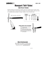
5. Center the laser beam onto the fluorescent plate. If you have purchased the beam splitter
for higher energy density beams, mount the beam splitter to the barrel of the X1 image
converter behind the locking nut as shown.
X1 UV Image Converter with beam splitter option on a Spiricon camera
Camera function is similar with both LBA and BeamGage software. Consult the
respective operator’s manuals to learn how to setup the system for either pulsed or
CW mode whichever applies. Since UV converters are commonly used with
pulsed Excimer lasers the following example discusses pulsed mode operation.
The UV converter works best in darkened room light.
2. Operating the Image Converter with a Pulsed Laser Beam
1. The 1X converter may slightly reduce or magnify the imaged beam,
thus the scaling values in the software may need to be adjusted to
compensate for this error. The magnification number shown on the
barrel of the converter will tell you if the beam is slightly larger or
smaller. Use this factor as needed in BeamGage or LBA to adjust
the spatial results computations.
2. Center the laser beam on the fluorescent plate at the entrance of the
image converter. Make sure the energy density of the beam is
within the limits given by the specification. It is best to eliminate
sources of stray light such as excessive room light. If the 90 degree
beam splitter is being used, place it so the reflected beam is
centered on the fluorescent plate.
3. Set the camera to pulsed mode as described in the instruction
manual. Synchronize the laser pulses with the camera as described
in the manual.
4. If the laser is a strong source of visible light as well as UV light
(such as the flash lamp light coming out of the laser) you may have
to place the camera-image converter assembly at an angle of ~5
degrees to the laser beam. In this way, the CCD will see the light
scattered from the fluorescent plate but not the visible light from the
laser.
ND Filter
8mm Spacer for 4.5mm
back focal cameras
Optional wedge beam
splitter (SPX17015)
Locking ring for
beam splitter
Focusing barrel
for UV plate
Locking ring for
focusing barrel

Document No 50374-001 Page 7 of 7 Rev A 05/2016
5. Add or remove ND filter attenuation as needed, but maintain the
12mm spacing distance when used on 4.5mm back focus cameras or
the 4mm distance when used on CS back focus cameras.
6. Adjust the Focusing barrel containing the fluorescent plate for the
sharpest image on the CCD. When best focus is found lock it with
the locking nut. (Note that the position has been adjusted in the
factory and you should ordinarily not have to change the original
focus setting).
Specifications
Spectral range
193 to 360nm
Minimum signal
~1uJ/cm² with blank filter
Saturation
intensity
~15mJ/cm² at 193nm, ~20mJ/cm² at 248nm
with included filter
20x greater with optional beam splitter
Resolution
35µm x 35µm
Damage threshold
100W/cm² or 2J/cm² with beam splitter
Aperture
Maximum beam size is the same as for the particular
camera used since the image size is not changed
from the original beam size.
Table 1 – X1 UV Image Converter specifications
(1) Above 310nm the glass begins to transmit UV light. Therefore you may see some
of the original laser’s light also as background interference.
/