Page is loading ...

ASSEMBLY & OPERATING INSTRUCTIONS
Important: Read these instructions for use carefully so as to familiarize yourself with the
appliance before connecting it to its gas container. Keep these instructions for future
reference
LPGSASA Permit Number (1185-33/1-RSA-12-A)
www.megamaster.co.za
Manufactured in China· Distributed by Mega Group · PO Box 15, Woodlands, 0027, South Africa· Tel: +27(0)12 802 1515
dWARNING
To reduce the risk of fire, burn hazard or other injury,
read the manual carefully and completely before
using your grill.
dfgWARNING
This grill is not intended to be
installed in or on recreational
vehicles and/or boats.
dfgWARNING
FOR OUTDOOR USE ONLY.

Table of Contents
Lighting Instruction. . . . . . . . . . . . . . . . . . . .
Care and Maintenance . . . . . . . . . . . . . . . . .
Trouble Shooting . . . . . . . . . . . . . . . . . . . . .
Grill Cooking Chart . . . . . . . . . . . . . . . . . .. .
Limited Warranty . . . . . . . . . . . . . . . . . . . . .
28
29
30-31
32
33
Safety Instruction . . . . . . . . . . . . . . . . . . . . .
Package Contents
List . . . . . . . . . . . . . . . . .
Hardware
Contents . . . . . . . . . . . . . . . . . . . .
Exploded
View . . . . . . . . . . . . . . . . . . . . . . . .
Part List . . . . . . . . . . . . . . . . . . . . . . . . . . . .
Assembly Instruction . . . . . . . . . . . . . . . . . .
Gas Hook –Up . . . . . . . . . . . . . . . . . . . . . . .
Installer Final Check List. . . . . . . . . . . . . . . .
Leak Testing . . . . . . . . . . . . . . . . . . . . . . . .
Operating
Instruction . . . . . . . . . . . . . . . . . . .
Grill Lighting Instruction . . . . . . . . . . . . . . . .
2-7
8-9
10
11
12-13
14-22
23
24
24-25
26
27
25
DANGER
If you smell gas:
1. Shut off gas to the appliance.
2. Extinguish any open flame.
3. Open lid.
4. If odor continues, keep away from the
appliance and immediately call your
gas supplier or your fire department.
WARNING
1. Do not store or use gasoline or other
flammable liquids or vapors in the
vicinity of this or any other
appliance.
2. An LP gas cylinder not connected
for use shall not be stored in the
vicinity of this or any other
appliance.
2
Safety Instruction

1. Never operate this appliance unattended.
2. Never operate this appliance within 10 ft (3 m) of any structure, combustible
material or other gas cylinder.
3. Never operate this appliance within 25 ft (7.5 m) of any flammable liquid.
4. Do not fill cooking vessel beyond maximum fill line.
5. Heated liquids remain at scalding temperatures long after the cooking process.
Never touch cooking appliance until liquids have cooled to 115ºF (45ºC) or less.
6. This appliance is not intended for and should never be used as a heater.
7. If a fire should occur, keep away from the appliance and immediately call your fire
department. Do not attempt to extinguish an oil or grease fire with water.
DANGER
Safety Instruction
3

Grill Installation Codes
Check your local building codes for the proper
method of installation. In the absence of local codes,
this unit should be installed in accordance with the
South African National Standard 1539, Storage and
Handling of Liquefied Petroleum Gases,
Correct LP Gas Cylinder Use
LP gas grill models are designed for use with a
standard 9kg LP Gas cylinder, not included with grill.
Never connect your gas grill to an LP gas cylinder
that exceeds this capacity.
WARNING
Do not try lighting this appliance without reading the
“LIGHTING INSTRUCTIONS” section of this manual.
CAUTION: Beware of Flashback
CAUTION: Spiders and small insects occasionally
spin webs or make nest in the grill
burner tubes during transit and
warehousing. These webs can lead
to gas flow obstruction, which could
result in a fire in and around burner
tubes. This type of fire is known as
“BURN-BACK” and can cause serious damage to your
grill and create an unsafe operating condition for the
user.
Although an obstructed burner tube is not the only
cause of “BURN-BACK”, it is the most common cause.
In the event of “BURN-BACK”, where the flame burns
back to the jet, immediately turn off the gas supply at
the burner control valve.
After ensuring that the flame is extinguished, re-light
the appliance as described in below. Should the
appliance again “BURN-BACK”, close the valves and
examine the mixing tube or burner for any obstruction.
If there are no obstructions and the burn back still
occurs, call a technician to examine the appliance and
make any necessary repairs.
Do not make any unnecessary adjustments or
modifications to this grill, a qualified LP gas technician
should do any adjustments.
To reduce the chance of “BURN-BACK”, you must
clean the burner tubes before assembling your grill,
and at least once a month in late summer or early fall
when spiders are most active. Also perform this burner
tube cleaning procedure if your grill has not been used
for an extended period of time. A clogged tube can be
lead to a fire beneath the grill.
If an external electrical source is utilized for lights
or rotisserie motors: The outdoor cooking gas
appliance, when installed, must be electrically
grounded in accordance with local codes or, in the
absence of local codes.
WARNING
Keep any electrical supply cord and the fuel supply
hose away from any heated surfaces
NOTE: The normal flow of gas through the regulator
and hose assembly can create a humming noise. A
low volume of noise is perfectly normal and will not
interfere with operation of the grill. If humming noise
is loud and excessive you may need to purge air from
the gas line or reset the regulator excess gas flow
device. This purging procedure should be done every
time a new LP gas cylinder is connected to your grill.
Visually check the burner flames prior to each use. The
flames should look like this picture. If they do not, refer
to the burner main tenancy part of this manual.
4
Safety Instruction
It must be used with a 2, 8 kPa regulator that
complies with Maximum LP gas cylinder size is 30cm
in diameter by 52cm tall. .

Safety Instruction
LP-Gas Supply System
• If the information is not followed exactly, a fire
resulting in death or serious injury could occur.
• A 9kg cylinder of approximately 30cm in diameter
by 52cm high is the maximum size LP gas
cylinder to use.
• The safety feature prevents the cylinder from
being overfilled, which can cause malfunction of
the LP gas cylinder, regulator and/or grill.
• The LP gas supply cylinder to be used must be
constructed and marked in accordance with the
specifications for LP Gas cylinders in RSA .
• The LP gas cylinder must have a shutoff valve
terminating in an LP valve outlet that is
compatible with a Type 1. LP gas supply cylinder
must have a shut off valve terminating in a valve
outlet specified for connection type QCC1 in the
standard for compressed gas cylinder valve
outlet and inlet connection. LP gas supply
cylinder must be fitted with an Overfill Protection
Device (O.P.D) The LP gas cylinder must also
have a safety relief device that has a direct
connection with the vapor space of the cylinder.
• The cylinder supply system must be arranged for
vapor withdrawal.
• The LP gas cylinder used must have a collar to
protect the cylinder valve.
• Place dust cap on cylinder valve outlet whenever
the cylinder is not in use. Only install the type of
dust cap on the cylinder valve outlet that is
provided with the cylinder valve. Other types of
cap or plugs may result in leakage of gas.
• Never connect an unregulated LP gas cylinder to
your gas grill.
• This outdoor cooking gas appliance is equipped
with a high capacity hose/regulator assembly for
connection to a standard 9kg. LP gas cylinder.
• Have your LP gas cylinder filled by a reputable
LP gas dealer and visually inspected and re-
qualified at each filling.
• Do not store a spare LP gas cylinder under or
near this appliance.
• Never fill the cylinder beyond 80 percent full.
• Always keep LP gas cylinders in an upright
position.
• Do not store or use gasoline or other flammable
vapors and liquids in the vicinity of this or any
other appliance.
• The gas must be turned off at the supply cylinder
when the outdoor cooking gas appliance is not in
use.
• LP gas cylinder must be stored outdoors in a
well-ventilated area and out of reach of children.
Disconnected LP gas cylinders must not be
stored in a building, garage or any other enclosed
area.
• Do Not obstruct the flow of ventilation air around
the gas grill housing. Only use the regulator and
the hose assembly supplied with your gas grill.
Replacement regulators and hose assemblies
must be those specified in this manual.
• The regulator and hose assembly must be
inspected before each use of the grill. If there is
excessive abrasion or wear or if the hose is cut, it
must be replaced prior to the grill being put into
operation. The replacement hose assembly shall
be that specified by the manufacturer.
• Pressure regulator and hose assembly supplied
with the outdoor cooking gas appliance must be
used. Never substitute other types of regulator.
Contact customer service for manufacturer
specified replacement parts.
• This outdoor cooking gas appliance is equipped
with a pressure regulator comply with the
standard for LP gas products in South Africa.
• Do not use briquettes of any kind in the grill.
• The grill is designed for optimum performance
without the use of briquettes. Do not place
briquettes on the radiant as this will block off the
area for the grill burners to vent. Adding
briquettes can damage ignition components and
knobs, and void the warranty.
• Keep the back and side cart free and clear from
debris. Keep any electrical supply cord, or the
rotisserie motor cord away from the heated areas
of the grill.
• Never use the grill in extremely windy conditions.
If located in a consistently windy area
(oceanfront, mountaintop, etc.) a windbreak will
be required. Always adhere to the specified
clearance.
• Never use a dented or rusty propane cylinder.
• Keep any electrical supply cord and the fuel
supply hose away from any heated surface.
• While lighting, keep your face and hands as far
away from the grill as possible.
• Burner adjustment should only be performed after
the burner has cooled.
• Storage of an outdoor cooking gas appliance
indoors is permissible only if the cylinder is
disconnected and removed from the outdoor
cooking gas appliance.
• When your gas grill is not in use the gas must be
turned off at LP gas cylinder.
5

PROPER PLACEMENT AND CLEARANCE OF
GRILL
• Never use your gas grill in a garage, porch,
shed, breezeway or any other enclosed area.
Your gas grill is to be used outdoors only.
Do Not install this unit into combustible
enclosures.
Minimum clearance from sides and back of
unit to combustible construction, 24 inches
(61cm) from sides and 24 inches (61cm) from
back.
• DO NOT use this appliance under overhead
combustible surfaces. This outdoors cooking
gas appliance is not intend to be installed in
or on recreational vehicles and/or boats.
WARNING
Your grill will get very hot. Never lean over the cooking
area while using your grill. Do not touch cooking
surfaces, grill housing, lid or any other grill parts while
the grill is in operation, or until the gas grill has cooled
down after use.
Failure to comply with these instructions may
result in serious bodily injury.
CAUTION: TO ENSURE CONTINUED PROTECTION
AGAINST RISK OF ELECTRIC SHOCK, CONNECT
TO PROPERLY GROUNDED OUTLETS ONLY, TO
REDUCE THE RISK OF ELECTRIC SHOCK, KEEP
EXTENSION CORD CONNECTION DRY AND OFF
THE GROUND.
INSECT WARNING
Spiders and insects can nest in the burners of this and
any other grill, and cause the gas to flow improperly.
This is a very dangerous condition, which can cause a
fire to occur behind and beneath the valve panel,
thereby damaging the grill and making it unsafe to
operate. Inspect the grill at least twice a year.
WARNING
Keep a spray bottle of soapy water near the gas
supply valve and check the connections before each
use.
DO NOT USE ALUMINUM FOIL TO LINE THE GRILL
RACKS OR GRILL BOTTOM.
This can severely upset combustion airflow or trap
excessive heat in the control area.
DO NOT LEAVE THE GRILL UNATTENDED WHILE
COOKING.
SAFETY PRACTICES TO AVOID PERSONAL
INJURY
When properly cared for your grill will provide safe,
reliable service for many years. However, extreme care
must be used as the grill produces intense heat that
can increase accident potential. When using this
appliance basic safety practices must be followed,
including the following:
Do not repair or replace any part of the grill unless
specifically recommended in this manual. All other
service should be referred to a qualified technician.
This grill is not intended to be installed in or on
recreational vehicles or boats.
Children should not be left alone or unattended in an
area where the grill is being used. Do not allow them to
sit, stand or play in or around the grill at any time.
Do not store items of interest to children around or
below the grill.
Do not permit clothing, pot holders or other flammable
materials to come in contact with or too close to any
grate, burner or hot surface until it has cooled. The
fabric could ignite and cause personal injury.
For personal safety, wear proper apparel. Loose fitting
garments or sleeves should never be worn while using
this appliance. Some synthetic fabrics are highly
flammable and should not be worn while cooking.
Only certain types of glass, heat-proof glass ceramic,
earthenware, or other glazed utensils are suitable for
grill use. These materials may break with sudden
temperature changes. Use only on low or medium heat
settings in accordance with the manufacturer’s
guidelines.
6
Safety Instruction

Do not heat unopened food containers. A build-up of
pressure may cause the containers to burst.
Use a covered hand when opening the grill lid.
Never lean over an open grill.
When lighting a burner, pay close attention to what
you are doing. Make certain you are aware of which
burner you are lighting, so your body and clothing
remain clear of open flames.
When using the grill, do not touch the grill rack,
burner grate or immediate surroundings as these
areas become extremely hot and could cause burns.
Use only dry potholders. Moist or damp potholders on
hot surfaces may cause steam burns. Do not use a
towel or bulky cloth in place or potholders. Do not
allow potholders to touch hot portions of the grill rack.
Grease is flammable. Let hot grease cool before
attempting to handle it. Do not allow grease deposits
to collect in the grease tray at the bottom of the grill’s
firebox. Clean the grease tray often
Do not use aluminum foil to line the grill racks or grill
bottom. This can severely upset combustion air flow
or trap excessive heat in the control area.
For proper lighting and performance of the burners
keep the burner ports clean. It is necessary to clean
them periodically for optimum performance. The
burners will only operate in one position and must be
mounted correctly for safe operation.
Clean the grill with caution. To avoid steam burns, do
not use a wet sponge or cloth to clean the grill while it
is hot. Some cleaners produce toxic fumes or can
ignite if applied to a hot surface.
Turn off grill controls and make certain the grill is cool
before using any type of aerosol cleaner on or around
the grill. The chemical that produces the spraying
action could, in the presence of heat, ignite or cause
metal parts to corrode.
Do not use the grill to cook excessively fatty meats or
other products which promote flare – ups.
Do not operate the grill under unprotected
combustible constructions. Use only in well ventilated
areas. Do not use in buildings, garages, sheds,
breezeways or other such enclosed areas.
WARNING
This outdoor cooking gas appliance is not
intended to be installed in or on boats. And
other recreational vehicles.
7
Safety Instruction
Keep the area surrounding the grill free from
combustible materials including, fluids, trash, and
vapors such as gasoline or charcoal lighter fluid.
Do not obstruct the flow of combustion and
ventilation air.

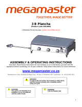
D
E
F
A
B
C
G
H
I
J
K
L
M
N
O
A . Firebox assembly-1pc
C. Right door -1pc B. Left door -1pc
E. Right side panel -1pc D. Left side panel -1pc F. Bottom panel -1pc
G. Left side shelf -1pc H. Side burner -1pc
I. Cooking grid with hole
-2pcs
K. Warming rack -1pc J. Grease pan -1pc L. Cart frame-1pc
M. Cart leg, front left-1pc N. Cart leg, rear left-1pc O. Cart leg, front right-1pc
Package Contents List
D
E
F
A
B
C
G
H
I
J
K
L
M
N
O

P Q R
S T
U
V
W X
Y
Z AA
AB
AC AD
AE AF
AG
V. Grease cup-1pc
AE. Battery -1pc
AC. Door iron piece-1pc
R. Side burner cooking
grid -1pc
Q. Door handle -2pcs
AF . Swivel caster -1pc
AG . Swivel caster with brake
-1pc
Y. Flame tamer -5pcs
S. Side burner -1pc
AD. cylinder support bracket-2pcs
AA. Right Triangle bracket -1pc Z. Left Triangle bracket -1pc
AB. Right Triangle bracket -1pc
P. Cart leg, rear right -1pc
T. Wheels -2pcs U. Wheel caps -2pcs
X. Grease pan support
bracket, left -1pc
Y. Grease pan support
bracket, left -1pc

Hardware Contents
10
Screw
1/4"x 15mm
Description
Item
Quantity
Specification
1
Screw
2
5/32"x 10mm
8
12

Explode View
11
1
2
2
3
3
4
7
5
6
6
8
9
10
11
12
13
14
15
16
17
17
18
19
20
21
22
23
24
25
27
26
28
29
30
31
32
33
34
35
36
37
38
39
40
41
42
28
43
44
45
46
47
48
49
50
51
52
53
54
55
56
45
57
57
58
62
59
60
61
60
59
61

No
.
Part (Description)
Warranty
coverage
(year)
QT
Y
No
.
Part (Description)
Warranty
coverage
(year)
QTY
1 Main lid 1 1 30 Side shelf, left 1 1
2 Main lid screw 1 2 31 Side shelf hooks 1 3
3 Main lid screw cover 1 2 32 Grease cup
1 1
4 Temperature gauge 1 1 33 Grease tray 1 1
5 Main lid handle 1 1 34
Grease tray support
bracket, left
1 1
6 Hood buffer A 1 2 35
Grease tray support
bracket, right
1 1
7 Logo 1 1 36 Side burner lid hinge rod 1 1
8 Warming rack 1 1 37 Side burner lid 1 1
9 Cooking grid 1 2 38 Side burner cooking grid 1 1
10 Flame tamer
1
5 39 Side burner igniter wire 1 1
11 Main burner
3
5 40
Side burner bowl
assembly
1 1
12 Main burner igniter wire A
1
1 41 Side burner pipe 1 1
13 Main burner igniter wire B
1
1 42 Side burner control panel 1 1
14 Main burner igniter wire C
1
1 43 Swivel caster with Brake 1 1
15 Main burner igniter wire D 1 1 44 Cart leg, rear left 1 1
16 Main burner igniter wire E 1 1 45 Wheels 1 2
17 Hood buffer B 1 2 46 Cart leg, rear right 1 1
18
Main burner bowl
assembly
Non-
replaceable
1 47
Triangle bracket, right
1 1
19 Front baffle 1 1 48
Triangle bracket, left
1 1
20 Main gas valve 1 5 49 Side panel, left 1 1
21 Main manifold 1 1 50 Cart leg, front left 1 1
22
Side burner Flex Gas Line
1 1 51 Bottom panel 1 1
23 Side Burner Gas valve 1 1 52 Door iron piece 1 1
24 Regulator, LP 1 1 53 Swivel caster 1 1
25 Main control panel 1 1 54 cylinder support bracket 1 1
26 Pulse igniter module 1 1 55 Cart leg, front right 1 1
27 Bezel 1 5 56 Side panel, right 1 1
28 Control Knob 1 6 57 Wheel cover 1 2
29 Side shelf front panel, left 1 1 58 Door, right 1 1
12

No
.
Part (Description)
Warranty
coverage
(year)
QT
Y
No
.
Part (Description)
Warranty
coverage
(year)
QTY
59 Door pivot, upper 1 2 61 Door pivot, bottom 1 2
60 Door handle assembly 1 2 62 Door, left 1 1
12

Assembly Instructions
2. Side panel Assembly
a) Loosen, but do not remove the screws that are pre-
assembled on the cart leg, front left (M) and cart leg,
rear left (N). Attach cart leg, front left (M) and cart leg,
rear left (N) to side panel, left (D) by aligning the holes
on the side panel, left (D). Tighten the screws that were
loosened above.
Note: make sure the flat side of side panel, left (D)
faces inside to the right when attaching. Show in Fig. 2.
Fig. 1
1. Caster Assembly
Mount the swivel caster onto the cart leg, front left
(M), mount the swivel caster with brake onto the
cart leg, rear left (N), then tighten it by wrench.
Show in Fig. 1.
13
Fig. 2
b) Loosen, but do not remove the screws that are pre-
assembled on the cart leg, front right (O) and cart leg,
rear right (P). Attach cart leg, front right (O) and cart
leg, rear right (P) to side panel, right (E) by aligning
the holes on the side panel, right (E). Tighten the
screws that were loosened above.
Note: make sure the flat side of side panel, right (E)
faces inside to the left when attaching. Show in Fig.
3.
Fig. 3
D
M
N
E
O
P
M
N

3. Bottom panel Assembly
a). Loosen, but do not remove the screws that are
pre-assembled on the side of the bottom panel (F),
align the holes on the cart leg, front left (M) and cart
leg, rear left (N), then place the cart legs onto the
screws that were loosened in the bottom panel (F) as
shown in Fig. 4.
b) Tighten the screw from outside to inside, there is a
hole in the outside of the cart leg. As shown in Fig. 4.
c) Repeat step 3a and 3b to attached right legs to the
bottom panel, make sure all screws are tight.
Fig. 4
Fig. 5
14
4. Cart frame Assembly
a). Loosen, but do not remove the screws that are
pre-assembled on the cart leg, front left (M) and Cart
leg, front right (O). Attach Cart leg, front left (M) and
Cart leg, front right (O) to the Cart Frame (L) ,by
aligning the holes on the cart frame (L), tighten the
screws that were loosened above. as shown in Fig. 5.
Fig. 6
5. Door Triangle Bracket Assembly
a) Loosen but do not remove four screws mount the
Left Side Panel (D) and Bottom Panel (F),
two screws on cart Right Side Panel (E)
and two on the Bottom Panel (F). Align the
holes of the left triangle bracket (Z) with screws on
Left Side Panel (D) and Bottom Panel (F).
Then tighten the screws as shown in Fig. 6.
b) Repeat the steps a) for attaching the
triangle bracket (AA) to the Right Panel (E) and
bottom Panel (F)
F
M
N
M
M
L
Z
AA
F
D
E

Fig. 7
7. cylinder support bracket Assembly
Mount the cylinder support bracket (AD) onto the
bottom panel (F) using four screws(1) .as show in
Fig. 8.
Fig. 9
8. Door iron piece Assembly
Mount the Door iron piece (AC) on the middle of the
bottom panel (F) using two screws(2) as show in Fig.
9.
6. Wheel Assembly
a). Remove the nuts and washers which are pre-
assembled on the short axle, place the wheels (T) on
the Axle attached to the Cart leg, Front Right (O) and
Cart Leg, Back Right (P),.As shown in Fig.7.
b) Place washers and nuts to the axle and tighten the
nuts.
c) Attached the Wheel caps on both Wheels as
shown in Fig.7
Fig. 8
O
P
T
U
AD
T
AC
F

Fig.10
9.Grease pan support bracket
Assembly
a) Attached Grease support bracket, left
(X) to the Cart leg, front left (M ) and
Cart leg, rear left (N )using two screws
and tightened it , as how in fig 10.
b) Repeat step a) to attach Grease
support bracket, right (Y) to the Cart
leg, front right (O) and Cart leg, rear
right (P)
10. Door Assembly
a) Attached the door handle assembly (Q) to the
each door (B&C) using four screws, as shown
in Fig. 11.
HINT: Two screws for each door.
Fig. 11
Fig.12
b). Insert the two door’s pivots into the both
holes of the cart frame, front (L) and bottom
panel (F) as shown in Fig. 12.
15
X
Y
P
O
M
N
B
C
Q
L
F

Fig.13
11. Firebox Assembly
a). Remove the firebox assembly (A) from the
carton and carefully place onto the grill cart. As
shown in Fig. 13.
CAUTION The firebox assembly is
heavy and will require two or more people to lift
and position onto grill cart. Failure to do so
may result in injury.
Fig.14
b). Attach firebox to the left and right side
panels by using four screws. As shown in
Fig. 14.
12. Side Burner Assembly
a). Loosen the two screws which pre-assembled
onto firebox right side panel (E) but do not
remove Completely. Remove the two screws that
are attached to the main control panel.
b). Align the holes on Side Burner Shelf (H) with the
loosened screws located on the side panel.
c). Secure Side Burner Shelf (H) from inside firebox
using two screws that were removed in step 9a
to attached the Side Burner Shelf (H) to the main
firebox.
d). Secure the Side Burner Shelf Control panel and
main control panel by two screw which are pre-
assembled on the main control panel. As shown
in Fig.15.Tighten all screws.
e). Tighten screws loosened in9b. Ensure all screws
are tight.
Fig.15
A
E
H

Fig.16
13. Side Burner Valve Installation
a) Loosen the screws which pre-assemble on the
side burner gas valve then attach to the bezel which
pre-assembled on the control panel, fix with vertical
gourd holes, then tighten the screws. As shown in Fig. 16.
Fig.17
b) Insert Side Burner Control Knob (AB) onto the
valve stem and tighten it. As shown in Fig. 17
Fig.18
14. Side Burner Installation
a) From underneath the side burner remove
two screws which are assembled on the
bottom of the side burner shelf (H). Open
side burner lid and place the Side Tube
Burner (S) through the opening. Place the
Side Tube Burner (S) tube over the side
burner gas valve and make sure
Side Burner gas valve is inserted into side burner tube.
As shown in Fig.18.
AB
H
S

Fig. 21
16
b). Then with two screws secure the side burner
from underneath to the Side Burner Shelf ().
As shown in Fig.19.
C). Connect ignition wire from Firebox Assembly (H)
control panel to the side burner igniter pin from
underneath the Side Burner Shelf & Control Panel As
Shown in Fig.19.
Noted: the There should be 3mm gap between side burner
Igniter wire and Side burner. Shown in Fig.20.
Fig.19
Side burner
lgniter wire
Side burner
3mm
Fig.20
15. Left Side Shelf Assembly
Repeat Step 10 to assemble Left side Shelf (G).
As shown in fig.21.
H
G
/