Page is loading ...

AP-6511E Access Point
INSTALLATION GUIDE

2 AP-6511E Access Point
MOTOROLA SOLUTIONS and the Stylized M Logo are registered in the US Patent & Trademark Office. © Motorola Solutions,
Inc. 2014. All rights reserved.

Installation Guide 3
1.0 Introduction . . . . . . . . . . . . . . . . . . . . . . . . . . . . . . . . . . . . . . . . . . . . . . . . . . . . . . 5
1.1 Document Conventions . . . . . . . . . . . . . . . . . . . . . . . . . . . . . . . . . . . . . . . . . . . . 5
1.2 Warnings . . . . . . . . . . . . . . . . . . . . . . . . . . . . . . . . . . . . . . . . . . . . . . . . . . . . . . . 6
1.3 Site Preparation . . . . . . . . . . . . . . . . . . . . . . . . . . . . . . . . . . . . . . . . . . . . . . . . . . 6
1.4 AP-6511E Package Contents. . . . . . . . . . . . . . . . . . . . . . . . . . . . . . . . . . . . . . . . . 6
1.5 Features . . . . . . . . . . . . . . . . . . . . . . . . . . . . . . . . . . . . . . . . . . . . . . . . . . . . . . . . 6
2.0 Hardware Installation . . . . . . . . . . . . . . . . . . . . . . . . . . . . . . . . . . . . . . . . . . . . . . 7
2.1 Installation Instructions . . . . . . . . . . . . . . . . . . . . . . . . . . . . . . . . . . . . . . . . . . . . 8
2.2 Precautions . . . . . . . . . . . . . . . . . . . . . . . . . . . . . . . . . . . . . . . . . . . . . . . . . . . . . . 9
2.3 Access Point Placement . . . . . . . . . . . . . . . . . . . . . . . . . . . . . . . . . . . . . . . . . . . . 9
2.4 Power Injector System . . . . . . . . . . . . . . . . . . . . . . . . . . . . . . . . . . . . . . . . . . . . . 9
2.5 Wall Mount Installation . . . . . . . . . . . . . . . . . . . . . . . . . . . . . . . . . . . . . . . . . . . 10
2.6 Telco Box Installation . . . . . . . . . . . . . . . . . . . . . . . . . . . . . . . . . . . . . . . . . . . . . 13
2.7 AP-6511E Antennas . . . . . . . . . . . . . . . . . . . . . . . . . . . . . . . . . . . . . . . . . . . . . . 17
2.8 LED Indicators . . . . . . . . . . . . . . . . . . . . . . . . . . . . . . . . . . . . . . . . . . . . . . . . . . . 17
3.0 Basic WiNG Express Access Point Configuration . . . . . . . . . . . . . . . . . . . . 18
4.0 Specifications. . . . . . . . . . . . . . . . . . . . . . . . . . . . . . . . . . . . . . . . . . . . . . . . . . . . 28
4.1 Electrical Characteristics . . . . . . . . . . . . . . . . . . . . . . . . . . . . . . . . . . . . . . . . . . 28
4.2 Physical Characteristics . . . . . . . . . . . . . . . . . . . . . . . . . . . . . . . . . . . . . . . . . . . 28
4.3 Radio Characteristics . . . . . . . . . . . . . . . . . . . . . . . . . . . . . . . . . . . . . . . . . . . . . 29
5.0 Regulatory Information . . . . . . . . . . . . . . . . . . . . . . . . . . . . . . . . . . . . . . . . . . . . 30
5.1 Regulatory Overview. . . . . . . . . . . . . . . . . . . . . . . . . . . . . . . . . . . . . . . . . . . . . . 30
5.2 Wireless Device Country Approvals . . . . . . . . . . . . . . . . . . . . . . . . . . . . . . . . . . 30
5.2.1 Country Selection - Note for AP & Wireless Controller. . . . . . . . . . . . . . . 30
5.2.2 Frequency of Operation - FCC and IC . . . . . . . . . . . . . . . . . . . . . . . . . . . . . 31
5.3 Health and Safety Recommendations . . . . . . . . . . . . . . . . . . . . . . . . . . . . . . . . 31
5.3.1 Warnings for the use of Wireless Devices . . . . . . . . . . . . . . . . . . . . . . . . 31
5.3.2 Potentially Hazardous Atmosheres - Fixed Installation . . . . . . . . . . . . . . . 31
5.3.3 Safety in Hospitals . . . . . . . . . . . . . . . . . . . . . . . . . . . . . . . . . . . . . . . . . . . 31

4 AP-6511E Access Point
5.4 RF Exposure Guidelines . . . . . . . . . . . . . . . . . . . . . . . . . . . . . . . . . . . . . . . . . . . 33
5.4.1 Safety Information . . . . . . . . . . . . . . . . . . . . . . . . . . . . . . . . . . . . . . . . . . . 32
5.5 International . . . . . . . . . . . . . . . . . . . . . . . . . . . . . . . . . . . . . . . . . . . . . . . . . . . . 32
5.6 EU . . . . . . . . . . . . . . . . . . . . . . . . . . . . . . . . . . . . . . . . . . . . . . . . . . . . . . . . . . . . 32
5.7 US and Canada . . . . . . . . . . . . . . . . . . . . . . . . . . . . . . . . . . . . . . . . . . . . . . . . . . 32
5.8 Power Supply . . . . . . . . . . . . . . . . . . . . . . . . . . . . . . . . . . . . . . . . . . . . . . . . . . . 33
5.9 Radio Frequency Interference Requirements - FCC . . . . . . . . . . . . . . . . . . . . . . 33
5.10 Radio Frequency Requirements - Canada. . . . . . . . . . . . . . . . . . . . . . . . . . . . . 33
5.10.1 Radio Transmitters . . . . . . . . . . . . . . . . . . . . . . . . . . . . . . . . . . . . . . . . . . 33
5.11 CE Marking and European Economic Area (EEA) . . . . . . . . . . . . . . . . . . . . . . . 34
5.12 Mexico . . . . . . . . . . . . . . . . . . . . . . . . . . . . . . . . . . . . . . . . . . . . . . . . . . . . . . . 34
5.13 Statement of Compliance . . . . . . . . . . . . . . . . . . . . . . . . . . . . . . . . . . . . . . . . . 34
5.14 Waste Electrical and Electronic Equipment (WEEE). . . . . . . . . . . . . . . . . . . . . 35
5.15 Turkish WEEE Statement of Compliance . . . . . . . . . . . . . . . . . . . . . . . . . . . . . 36
5.16 Japan (VCCI) - Voluntary Control Council for Interference Class B ITE . . . . . . 37
5.17 Korea Warning Statement for Class B ITE . . . . . . . . . . . . . . . . . . . . . . . . . . . . 37
5.17 Other Countries. . . . . . . . . . . . . . . . . . . . . . . . . . . . . . . . . . . . . . . . . . . . . . . . . 37
6.0 Motorola Solutions Support Center . . . . . . . . . . . . . . . . . . . . . . . . . . . . . . . . . 40

Installation Guide 5
1 Introduction
The AP-6511E is an enterprise class 802.11n Access Point, installed in minutes anywhere a CAT-5 (or better) cable
is located. The AP-6511E’s mechanical design is optimized for installation over a standard CAT-5 (or better) wall
jack. The AP does not protrude into the wall cavity, allowing for an efficient heat transfer and a universal
installation over a standard Telco wiring plate. The AP-6511E’s modular design allows the end-user to add switched
Ethernet ports as-needed, and attach a standard keystone or Leviton QuickPort® modular connector to the wall
plate.
The AP-6511E Access Point ships with a single dual-band radio supporting the 802.11a/b/g/n radio bands.
The AP-6511E receives all power and transfers data through the same CAT-5 or better Ethernet cable. There is no
additional power supply required. An 802.3af PoE Ethernet switch or mid span power injector is required.
The AP-6511E can be ordered for US deployment (AP-6511E-60010-US), deployment in Europe
(AP-6511E-60010-EU) or deployment outside of the US or Europe (AP-6511E-60010-WR).
1.1 Document Conventions
The following graphical alerts are used in this document to indicate notable situations:
NOTE Tips, hints, or special requirements that you should take note of.
CAUTION Care is required. Disregarding a caution can result in data loss or
equipment malfunction.
WARNING! Indicates a condition or procedure that could result in personal injury or
equipment damage.
!

6 AP-6511E Access Point
1.2 Warnings
• Read all installation instructions and site survey reports, and verify correct equipment installation before
connecting the Access Point.
• Remove jewelry and watches before installing this equipment.
• Verify the unit is grounded before connecting it to the power source.
• Verify any device connected to this unit is properly wired and grounded.
• Verify there is adequate ventilation around the device, and that ambient temperatures meet equipment
operation specifications.
1.3 Site Preparation
• Consult your site survey and network analysis reports to determine specific equipment placement, power
drops, and so on.
• Assign installation responsibility to the appropriate personnel.
• Identify and document where all installed components are located.
• Ensure adequate, dust-free ventilation to all installed equipment.
• Prepare Ethernet port connections.
• Verify cabling is within the maximum 100 meter allowable length.
1.4 AP-6511E Package Contents
An AP-6511E Access Point is available in integrated antenna and external antenna models. Contents differ
depending on the model ordered.
• AP-6511E Access Point
• Mounting plate (used for both wall mount and Telco Box installations)
• Mounting plate lock screw
• AP-6511E Installation Guide (This Guide)
• RJ-45 double plug interconnect cable
• Fast Ethernet port 1 interconnect cable
1.5 Features
• One RJ-45 PoE Ethernet port (built into the AP-6511E Access Point)
• Optional second RJ-45 Ethernet port utilizing a pass through (keystone) cable (included)
• Optional three port Ethernet expansion module (sold separately)
• 2 LED indicators
The pass through (keystone) cable provides an option to add a second Ethernet port before installing the AP-6511E.
The AP-6511E has one RJ-45 connector supporting an 10/100 Ethernet port and requires 802.3af compliant power
from an external source.
The AP-6511E ships with a single dual-band radio supporting the 802.11a/b/g/n radio bands.

Installation Guide 7
The Access Point contains runtime firmware which enables the unit to boot after either a power up or a watchdog
reset. The runtime firmware on the Access Point can be updated via the Ethernet interface.
The front of the AP-6511E has an access cover that can be removed to expose an additional connector. A three port
RJ-45 Ethernet expansion module connects to the hidden header and snaps onto the AP-6511E in place of the
access cover.
Remove the AP-6511E’s access cover by inserting a long pointed tool into the circular hole (opening) on the bottom
of the AP-6511E. Pull the access cover up and away from the AP-6511E. Reverse the procedure to install the
expansion module.
The Ethernet expansion module has three ports labeled FE2, FE3 and FE4.
The expansion module (KT-6511-0000D-WR) is a separately orderable component from Motorola Solutions.

8 AP-6511E Access Point
2 Hardware Installation
2.1 Installation Instructions
An AP-6511E Access Point mounts either on a wall, under a table or over a Telco Box. The AP-6511E is not plenum
rated.
The AP-6511E is mounted to a wall or Telco Box so the mounting plate is flush with the mounting surface.
The AP-6511E snaps on to the mounting plate without the use of tools or fastening hardware. Removal of the
AP-6511E from the mounting plate can be accomplished without the use of a tool. A mounting lock screw is
provided to help ensure a tamper resistant installation.
To prepare for the installation, perform the following:
1. Verify the contents of the box includes the intended AP-6511E Access Point model and accessory
hardware.
2. Review site survey and network analysis reports to determine the location and mounting position for the
AP-6511E Access Point.
3. Connect a CAT-5 or better Ethernet cable to a PoE compatible device and run the cable to the installation
site. Ensure there is sufficient cable slack to perform the installation steps.
NOTE The provided metal mounting plate is fastened to an existing standard
Telco in-wall box. The box is customer provided within the customer
building structure, and can be either plastic or metal in composition.
Screws and other mounting hardware are not include.
NOTE Once installed onto the mounting plate, the assembly can resist a
minimum of 10 lbs of force before unit breakage or accidental
disassembly.

Installation Guide 9
2.2 Precautions
Before installing an AP-6511E model Access Point:
• Verify the intended AP-6511E deployment location is not prone to moisture or dust.
• Verify the environment has a continuous temperature range between 0° C to 40° C.
2.3 Access Point Placement
For optimal performance, install the Access Point away from transformers, heavy-duty motors, fluorescent lights,
microwave ovens, refrigerators and other industrial equipment. Signal loss can occur when metal, concrete, walls
or floors block transmission. Install the Access Point in an open area or add Access Points as needed to improve
coverage.
To maximize the Access Point’s radio coverage area, Motorola Solutions recommends conducting a site survey to
define and document radio interference obstacles before installing the Access Point.
2.4 Power Injector System
When users purchase a WLAN solution, they often need to place Access Points in obscure locations. In the past, a
dedicated power source was required for each Access Point in addition to the Ethernet infrastructure. This often
required an electrical contractor to install power drops at each Access Point location. The Power Injector merges
power and Ethernet into one cable, reducing the burden of installation and allowing optimal Access Point
placement in respect to the intended coverage area.
A Motorola Solutions Power Injector (AP-PSBIAS-2P2-AFR) is recommended as the 802.3af compatible power
supply for the AP-6511E. The Power Injector is capable of providing 12.95 Watts up to 100 meters. The Power
Injector is separately ordered and not shipped with the AP-6511E. A separate Power Injector is required for each
Access Point comprising the network.
The Power Injector has no On/Off power switch. The Injector receives power and is ready for device connection and
operation as soon as AC power is applied. Refer to the Installation Guide shipped with the Power Injector for a
description of the device’s LEDs.The Power Injector can be installed free standing, on an even horizontal surface or
wall mounted using the Power Injector’s wall mounting key holes.
The following guidelines should be adhered to before cabling the Power Injector to an Ethernet source and an
Access Point:
• Do not block or cover airflow to the Power Injector.
• Keep the Power Injector away from excessive heat, humidity, vibration and dust.
• The Power Injector isn’t a repeater, and does not amplify the Ethernet signal. For optimal performance,
ensure the Power Injector is placed as close as possible to the Ethernet switch. This will allow the
AP-6511E to be deployed away from power drops.

10 AP-6511E Access Point
• Ensure the cable length from the Ethernet source (host) to the Power Injector and AP-6511E Access Point
does not exceed 100 meters (333 ft).
2.5 Wall Mount Installation
Ceiling mount requires holding the AP-6511E Access Point up against a T-bar of a suspended ceiling grid and
twisting the case onto the T-bar.
To install an AP-6511E model Access Point to a wall surface:
1. Attach the metal mounting plate (shipped with the AP-6511E) to a wall surface at the desired deployment
location.
The screws used to mount the bracket are customer provided and should be #6, with a 2.00 inch length.
CAUTION To avoid problematic performance and restarts, disable POE from a
wired controller port connected to an Access Point if mid-span power
sourcing equipment (PSE) is used between the two, regardless of the
manufacturer.
CAUTION Ensure AC power is supplied to the Power Injector using an AC cable
with an appropriate ground connection approved for the country of
operation.
NOTE Motorola Solutions recommends the following customer supplied
mounting accessories an AP-6511E wall mount installation:
2, screws, #6 x 2.00 inch pan head
2, wall anchors suitable for the #6 screws
!
!

Installation Guide 11
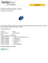
2. Connect one end of an RJ-45 cable into the wall mount connector on the AP-6511E as illustrated below.
3. If using the optional second RJ-45 Ethernet port (utilizing a pass through keystone cable), ensure the
following steps are completed:
a. Bend the cable into a “U” shape so the mini pin connector and the RJ-45 keystone cable are in close
proximity to one another.
b. Install the mini pin connector into the pin socket on the back of the AP-6511E. The connector is keyed
and can only be installed one way. Ensure the mini pin connector is connected securely.
c. Remove the blank plug from the keystone hole by gently pushing it out from the back.
d. Orient the RJ-45 keystone connector so the flexible keystone tab is away from the mini pin connector.
Tip the keystone RJ-45 while installing in the keystone opening so the solid locking tabs engage, then
rotate the RJ-45 forward until the tab snaps securely.

12 AP-6511E Access Point
4. Snap the AP-6511E on to the mounted wall plate. Use the locking screw to secure the unit. This connection
does not require the use of tools or fastening hardware.
Once installed, connections are hidden from forward view, with only the physical infrastructure cables
(Ethernet and power) extending from the AP-6511E.
5. Cable the Access Point using a Power Injector solution (AP-PSBIAS-2P2-AFR) as described in the
following:
a. Connect an RJ-45 CAT5 Ethernet cable between the network data supply (host) and the Power
Injector’s Data In connector.
b. Connect an RJ-45 CAT5 Ethernet cable between the Power Injector’s Data & Power Out connector
and the AP-6511E Access Point.
c. Ensure the cable length from the Ethernet source (host) to the Power Injector and Access Point does
not exceed 100 meters (333 ft). The Power Injector has no On/Off power switch. The Power Injector
receives power as soon as AC power is applied. For more information, see
Power Injector System.
6. Verify the behavior of the AP-6511E Access Point LEDs. For more information, see
LED Indicators.
7. The AP-6511E is ready to configure. For information on basic Access Point device configuration, see
Basic
WiNG Express Access Point Configuration.

Installation Guide 13
2.6 Telco Box Installation
For Telco Box installations, the AP-6511E is installed directly over the standard wall plate supplying Ethernet. All
cabled electrical connections are mode within a recessed well in the housing of the AP-6511E Access Point.
To install the AP-6511E Access Point over a Telco box:
1. Remove the cover of the CAT5 wall plate.
2. Snap out keystone connectors from existing plate.
3. Gently pull some cable out of the wall so it can be used with the AP-6511E Access Point.
4. Attach the metal mounting plate (shipped with the AP-6511E) to an existing standard Telco in-wall box.
NOTE The example above assumes the Telco Box has a 1 RJ11 phonejack and
1 RJ-45 10/100 Ethernet connection.

14 AP-6511E Access Point
The screws used to mount the bracket to the Telco Box are customer provided. You can use the same
screws that covered the existing wall plate if necessary.
Mount the bracket to the wall so the Telco Box is ready available behind the mounting plate.
5. Remove the blank plug before installing the RJ11 into the snap-in port.

Installation Guide 15
6. Install the RJ11 (keystone style) connector into the AP-6511E’s snap-in port.
7. If using the optional second RJ-45 Ethernet port (utilizing a pass through keystone cable), ensure the
following steps are completed:
a. Bend the cable into a “U” shape so the mini pin connector and the RJ-45 keystone cable are in close
proximity to one another.
b. Install the mini pin connector into the pin socket on the back of the AP-6511E. The connector is keyed
and can only be installed one way. Ensure the mini pin connector is connected securely.
c. Remove the blank plug from the keystone hole by gently pushing it out from the back.
d. Orient the RJ-45 keystone connector so the flexible keystone tab is away from the mini pin connector.
Tip the keystone RJ-45 while installing in the keystone opening so the solid locking tabs engage, then
rotate the RJ-45 forward until the tab snaps securely.
8. Install the RJ-45 double plug uplink jumper into the UP1/POE jack and connect it into the
RJ-45 Ethernet connector.
To PBX
RJ45 connector

16 AP-6511E Access Point
9. Snap the AP-6511E on to the mounted wall plate and secure the AP-6511E using the mounting plate lock
screw. This connection does not require the use of tools or fastening hardware.
10. Cable the Access Point using a Power Injector solution (AP-PSBIAS-2P2-AFR) as described in the
following:
e. Connect an RJ-45 CAT5 Ethernet cable between the network data supply (host) and the Power
Injector’s Data In connector.
f. Connect an RJ-45 CAT5 Ethernet cable between the Power Injector’s Data & Power Out connector
and the AP-6511E Access Point.
g. Ensure the cable length from the Ethernet source (host) to the Power Injector and Access Point does
not exceed 100 meters (333 ft). The Power Injector has no On/Off power switch. The Power Injector
receives power as soon as AC power is applied. For more information, see
Power Injector System.
11. Verify the behavior of the AP-6511E Access Point LEDs. For more information, see
LED Indicators.
12. The AP-6511E is ready to configure. For information on basic Access Point device configuration, see
Basic
WiNG Express Access Point Configuration
.

Installation Guide 17
2.7 AP-6511E Antennas
The AP-6511E model Access Point contains two internal (embedded) dual-band antennas supporting both the
802.11bgn (2.4 GHz) and 802.11an (5.0 GHz) bands. No customer assembly or antenna orientation is required.
The AP-6511E radio can transmit on one or two antennas depending on the operating modes. The radio can receive
on one or two antennas as well. The data rates supported are different in each case.
2.8 LED Indicators
An AP-6511E model Access Point has two LED activity indicators on the front of the unit.
The LEDs provide a status display indicating error conditions, transmission, and network activity for the 5 GHz
802.11a/n (amber) radio or the 2.4 GHz 802.11b/g/n (green) radio.
Task 5 GHz Activity LED (Amber) 2.4 GHz Activity LED (Green)
Unadopted On On
Normal
Operation
• If this radio band is enabled:
Blink at 5 second interval
• If this radio band is disabled:
Off
• If there is activity on this band:
Blink at a 1Hz
• If this radio band is enabled:
Blink at 5 second interval
• If this radio band is disabled:
Off
• If there is activity on this band:
Blink at a 1Hz
Firmware
Update
On Off
Locate AP
Mode
Blink at 5Hz
(Out of Phase with Activity LED)
Blink at 5Hz
(Out of Phase with Activity LED)

18 AP-6511E Access Point
3 Basic WiNG Express Access Point Configuration
For a WiNG Express SKU (AP6511E), both the WiNG Express UI and an over the air (OTA) provisioning configuration
are required for a basic setup and network connection. For a non WiNG Express SKU (AP6511), there’s no OTA
support, and the Access Point utilizes just the UI for its basic setup.
To provide the Access Point a basic configuration and access WiNG Express management functions:
1. Power up the Access Point.
The Access Point can be powered using an appropriately rated power adapter, POE injector or POE switch
resource.
2. Connect to the Access Point.
For WiNG Express models
:
Connect to the WiNG Express SSID. For Windows systems, locate the SSID by selecting the network icon
on the bottom right corner of the screen. For MAC systems, locate the SSID by selecting the network icon
on the top right corner of the screen.
Open a browser (Chrome, Firefox or Internet Explorer) and enter
http://express.motorolasolutions.com
. The login screen displays.
For non-WiNG Express models:
Refer to the bottom of the Access Point to obtain the numeric IP address used for connecting to the device.
Point the Web browser to the Access Point’s IP address. The login screen displays.
NOTE For information on using WiNG Express beyond this initial setup, refer to
the Motorola Solutions WiNG Express Users Guide to familiarize yourself
with the WiNG Express Access Point operating system. The guide is
available at https://portal.motorolasolutions.com/Support/US-EN
.

Installation Guide 19
3. Enter the default username admin in the Username field.
4. Enter the default password motorola in the Password field.
5. Select the Login button to load the management interface.
If this is the first time the WiNG Express interface has been accessed, a screen displays prompting for the
Access Point’s country code.
6. Select the Country Code specific to this Access Point’s deployment location.
Selecting the correct country is central to legal operation. Each country has its own regulatory restrictions
concerning electromagnetic emissions and the maximum RF signal strength that can be transmitted.
Select Apply to implement the selected Country Code. SKU's only support certain countries (for example:
a US SKU only includes US, Guam, Puerto Rico, American Samoa, US Virgin Islands and Mariana Island).
The Access Point automatically displays a Dashboard where users can assess network health and
conduct a diagnostic review of Access Point performance.
NOTE At some point in the Access Point’s initial setup, the default password
should be changed to enhance the security of the Access Point and WiNG
Express managed network. Refer to the Configuration > Management
screen to change the default password to a more secure password.

20 AP-6511E Access Point
7. Expand the Configuration menu item and select Basic.
8. Set the following Basic Configuration Settings for this Access Point:
• AP Name - Provide an AP Name used as this Access Point’s WiNG Express network identifier. If
setting this Access Point as a Virtual Controller, each Access Point managed by this Virtual Controller
lists this Access Point’s AP Name as its own. The AP Name is a required parameter.
• Country Code - If the Country Code was not set when the Access Point was initially powered on, set
the country now to ensure the Access Point’s legal operation. The Access Point’s wireless capabilities
are disabled until the required country code is set.
• Virtual Controller -Select this option to define this Access Point as a Virtual Controller capable of
managing and provisioning up to 24 Access Points of the same model. If selecting this Access Point
as a Virtual Controller, those Access Points managed by this Virtual Controller will list this Access
Point’s AP Name as its own. Only one Virtual Controller can be designated.
• Timezone - Use the drop-down menu to specify the geographic timezone where the Access Point is
deployed. Different geographic time zones have daylight savings clock adjustments, so specifying the
timezone correctly is important to account for geographic time changes.
• Date & Time - Set the date, hour and minute for the Access Point’s current system time. Specify
whether the current time is in the AM or PM.
• NTP Server - Optionally provide the IP address of a NTP server resource. Network Time Protocol (NTP)
manages time and/or network clock synchronization within the WiNG Express network. NTP is a
client/server implementation. Access Points (NTP clients) periodically synchronize their clock with a
master clock (an NTP server). For example, an Access Point resets its clock to 07:04:59 upon reading
a time of 07:04:59 from its designated NTP server.
9. Select Apply to implement the updates.
/