Videx Security KRV7X Owner's manual
- Category
- Door intercom systems
- Type
- Owner's manual

66250900 - V4.1 - 15/05/19
- 1 -
Kristallo Series
Art.KRV76-KRV78 - Installation instructions
Art.KRV76-KRV78
Handsfree videophones for systems using composite video signal (coax) or balanced (two wires)
112 42
155
182
29
A
B
E
F
C
D
Fig. 1
Art.KRV76 front
120
190
839
189
119
A
B
E
C
D
Fig. 2
Art.KRV78 front
DOL
SB
AL
LB
L
_
12Vin
12Vout
GND
V2/V
V1
+20
+VD
RS-232
ON ON
SW2
SW1
G
I
L
H
Fig. 3
Art.KRV78 back
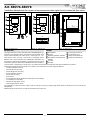
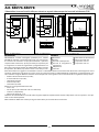
DESCRIPTION
Intelligent Hands free video monitor for the VX2200 digital sys-
tem using 3,5” OSD full colour active matrix LCD monitor, with
touch sensitive buttons for “door open / concierge call” , “an-
swer/camera recall”, “privacy / service” plus 5 navigation menu
buttons and 3 LEDs related to the videophone operation. For
the surface version only (Art.KRV76), a handset can also be used
in addition to the handsfree mode. Additional features include a
real time clock, a temperature sensor and a serial RS232 port for future integration with home automation systems.
The following programmable options are available via the OSD menu’s and navigation buttons:
• Call tone volume (3 levels);
• Speech volume (8 levels);
• Picture Brightness (8 levels);
• Picture Contrast (8 levels);
• Picture Hue (8 levels);
• Date & time;
• Privacy duration (from 30 minutes to 20 hours or unlimited);
• Call melodies (9 available);
• Number of rings (from 1 to 9);
• Intercommunication mode.
The videophone address and the video mode are set by the 8 way and 4 way dip-switch banks available on the rear side of the
videophone.
Additionally the Kristallo has an input for local door bell and alarm.
LEGEND
A
Microphone
B
Display
C
Operating buttons and LED’s
D
Navigation and adjustment
buttons
E
Speaker
F
Handset
G
Connection terminals
H
Serial Port RS-232
I
4 Way dip switch bank
L
8 Way dip switch bank
Rev.1.0

66250900 - V4.1 - 15/05/19
- 2 -
Kristallo Series
Art.KRV76-KRV78 - Installation instructions
PUSH BUTTONS AND CONTROLS
• Press this button during an incoming call to open the speech in duplex mode allowing free speech with the caller in
both directions (The related LED will illuminate).
• When the system is in standby, (No calls on the system) operation of this button will open the speech to the door sta-
tion. The related LED will illuminate. Press as many time as the ID value of the door panel to connect to.
• During a conversation, momentary operation of this button will end the call. The LED next to the button will switch o.
The system will automatically switch o when the conversation time expires.
• Press and hold this button (more than 1 second), during an incoming call or a conversation in progress, to allow the
user to answer a call from a visitor at the door station in SIMPLEX speech mode (The related LED will ash rapidly): re-
leasing the button will allow the user to listen to the visitor (The LED will ash slowly). Press and hold the button when
you talk to the visitor and release the button when you listen to the visitor.
• During a conversation, operation of this button will release the door from where the call originated. This will be conrmed by
an acoustic tone and the key icon on the top of the screen under the date, time & temperature row. If terminal “DL” is connected,
the “door open” LED next to the button will also be illuminated.
• When the system is in stand-by, a button press will book a call to the concierge (If available)
• When the system is in stand-by, press this button to enable the service for the programmed time: the related LED will illumi-
nate to signal the service enabled. During an incoming call, with the service enabled, the device does not emit any acoustic
signal. The service is disabled when the programmed time expires or pressing again the button.
• With the system in stand-by, keep pressed this button until the monitor switches on showing the programming menu
where you can set date & time, privacy duration, call tone volume, melody and number of rings. Once the menu is
enabled, proceed with settings by the menu navigation buttons.
• During an incoming call, press this button to reject the call. The visitor doesn’t receive any warning of the call rejected.
• During a conversation, press and keep pressed this button until the videophone emits a beep and the display shows
the “SRV” icon on the top of the display under the date, time & temperature row: the auxiliary output is operated and
the terminal “SB” is shorted to ground for 2 seconds.
• During a conversation, press this button to enter a programming menu that allows to set speech volume, picture
brightness, contrast and hue. Once the menu is enabled, proceed with settings by the menu navigation buttons.
Menu navigation buttons to be used during adjustment and programming menus. Via these buttons you can set the date
& time, the melody, the number of rings and the privacy duration and you can adjust the speech and call tone volume and
the picture brightness, contrast and hue.
When the system is in stand-by (No calls on the system), operation of this button to intercommunicate with other
extensions. Press as many time as the PHONE ID or the EXT. ID (it depends from the intercommunication mode) of the
videophone to call.
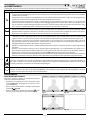
OPERATION
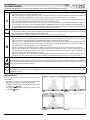
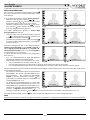
RECEIVING A CALL
During a call the display switches on showing the screen
on the right:
• To answer in hands free mode press the
button
Fig.1A (or pick up the handset on Art.KRV76);
• To open the door without speech to the visitor press
the button Fig.1B;
• To reject the call without informing the visitor press
the button Fig.1C.
15/12/11 14.5°C 09:23
Fig.1
15/12/11 14.5°C 09:23
MENU
PT T
Fig.1A
15/12/11 14.5°C 09:23
MENU
PT T
Fig.1B Fig.1C
Art.KRV76-KRV78
Handsfree videophones for systems using composite video signal (coax) or balanced (two wires)

66250900 - V4.1 - 15/05/19
- 3 -
Kristallo Series
Art.KRV76-KRV78 - Installation instructions
DURING THE CONVERSATION
During the conversation Fig.2:
• To switch from hands free to push to talk mode, keep
pressed the
until the related LED starts to ash
slowly Fig.2A. Keep pressed the
button to talk to
the visitor (the LED ashes quickly) and release the
button (the LED ashes slowly) to listen the visitor;
• To open the door press the button Fig.2B;
• To enable the secondary service keep pressed the
button until the activation signals (call tone plus mes-
sage) are received Fig.2C;
• To switch betwen Celsius or Fahrenheit degrees or
viceversa, press the button.
• To enter into programming menu press the
button
Fig.3.
15/12/11 14.5°C 09:23
MENU
PT T
Fig.2
15/12/11 14.5°C 09:23
PT T
Fig.2A
15/12/11 14.5°C 09:23
MENU
PT T
Fig.2B
15/12/11 14.5°C 09:23
M ENU
PT T
SRV
Fig.2C
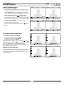
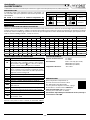
ADJUSTMENTS PROGRAMMING MENU
In the programming menu you can set:
• The speech volume (8 levels Fig.3);
• The picture brightness (8 levels Fig.3A);
• The picture contrast (8 levels Fig.3B);
• The picture hue (8 levels Fig.3C);
Adjust the selected option using the buttons
and
then conrm by the button to move to next option
or use the buttons to navigate the options.
With “EXIT” selected, press to exit from the menu or
do adjust other settings.
PARAMETERS PROGRAMMING
The programming consists of a number of settings that in
part are carried out by a specic OSD menu and the rest is
carried out by the two dip-switch banks on the rear side
of the videophone.
OSD
EXIT
Fig.3
OSD
EXIT
Fig.3A
OSD
EXIT
Fig.3B
OSD
EXIT
Fig.3C
Art.KRV76-KRV78
Handsfree videophones for systems using composite video signal (coax) or balanced (two wires)

66250900 - V4.1 - 15/05/19
- 4 -
Kristallo Series
Art.KRV76-KRV78 - Installation instructions
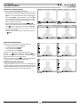
PROGRAMMINGS MENU
When the system is in stand-by, keep pressed the button
until the monitor switches on showing the screen to the left.
The rst programming option is the date & time Fig.4:
• change the values by the
and buttons;
• use buttons and and to move between the
elds to set (day, month, year, hours and minutes);
• conrm the setting by the button or the but-
ton when the eld minutes is selected. The system
goes to next programming step.
The second programming option is the privacy duration
Fig.4A (from 0 to 20 hours):
• adjust the value by the buttons
and (0 = privacy
duration unlimited, the service is disabled by pressing
again the button );
• conrm the value by the or . The system jump
to next programming option.
Proceed in the same way for the other programming
options: call tone volume (3 level Fig.4B), melody (9
options Fig.4C), number of rings (for 1 to 9 Fig.4D)
and service button duration (0 or from 1 to 99 seconds
Fig.4E from rmware 2.3 and later).
The “Service Button Duration” has a special programming:
• From 1 to 99 it indicates the number of seconds during
which the “SB” output is active when the service is enabled.
• By setting 0 value, the service operates in two ways :
1. When the videophone is in stand-by, a “Local Bell”
call (“LB” input terminal) automatically enables
the “SB” output for 30 seconds approx.;
2. When the videophone is switched on, by activat-
ing the service, the “SB” output terminal is enabled for 20 seconds.
The last setting is the intercommunication mode “IC” (from rmware 3.0 and later). Two intercommunication modes are available:
• To set the intercommunication for dierent apart-
ments (videophones with dierent PHONE ID) press
the button
until you select the “APT. MODE”
(Fig.4F). In stand-by mode, by pressing the button
one or more times you will be able to call the vid-
eophones with PHONE ID from 1 to 9.
• To set the intercommunication among extensions
in the same apartment (videophones with the same
PHONE ID but with dierent EXT. ID) select an EXTEN-
SION ID for this device from 1 to 9 (Fig.4G) by pressing
the buttons and . In stand-by mode, by pressing
the button one or more times you will be able to call the videophones with EXT. ID from 1 to 9 within the same apartment.
Once “EXIT” is selected, press
to exit or press the button to continue to change other programming options.
NOTE
From any of the two OSD menu’s, if the videophone switches o because of the timeout, the changes with not be stored.
09:2315/12/11
EXIT
Fig.4
01 . 5h
EXIT
Fig.4A
EXIT
Fig.4B
RINGS 6
EXIT
Fig.4D
MEL ODY 1
EXIT
Fig.4C
02 SEC
EXIT
Fig.4E
APT.MODE
EXIT
Fig.4F
EXT. ID: 2
EXIT
Fig.4G
Art.KRV76-KRV78
Handsfree videophones for systems using composite video signal (coax) or balanced (two wires)

66250900 - V4.1 - 15/05/19
- 5 -
Kristallo Series
Art.KRV76-KRV78 - Installation instructions
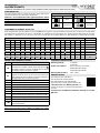
VIDEO MODE SW2
The video mode setup is carried out by the 4 way Dip-Switch
accessible from the rear side of the videophone.
Switches 3 and 4 adjust the video signal impedance. when
using more than one videomonitor in parallel (without a
video splitter) put both switches in the OFF position on all
but the last videomonitor (end of line).
VIDEO MODE
Switches 1,2 Mode
ON
1 32 4
Coax
ON
1 32 4
Balanced
75 OHM VIDEO TERMINATION
Switches 3,4 Termination
ON
1 32 4
Enabled
ON
1 32 4
Disabled
VIDEOMONITOR ADDRESS SETUP SW1
Each videomonitor must be address is binary (PHONE ID) using the 8 way dip switches located on the rear of the unit. Each switch
correspond to one bit which can have a value 0 (OFF) or 1 (ON). Each bit corresponds to a decimal weight depending on the posi-
tion: Switch 1 = decimal 1, 2=2, 3=4, 4=8, 5=16, 6=32, 7=64, 8=128. I.E. to set the address 37, put switches 1, 3 and 6 on (1+4+32=37).
SWITCHES DECIMAL WEIGHT ADDRESS
8 7 6 5 4 3 2 1 128 64 32 16 8 4 2 1
OFF OFF OFF OFF OFF OFF OFF ON 0 0 0 0 0 0 0 1 1
OFF OFF OFF OFF OFF OFF ON OFF 0 0 0 0 0 0 1 0 2
OFF OFF OFF OFF OFF OFF ON ON 0 0 0 0 0 0 1 1 3
OFF OFF OFF OFF OFF ON OFF OFF 0 0 0 0 0 1 0 0 4
OFF OFF ON OFF OFF ON OFF ON 0 0 1 0 0 1 0 1 37
ON OFF ON ON OFF ON OFF OFF 1 0 1 1 0 1 0 0 180
CONNECTION TERMINALS SIGNALS
DOL 12Vdc input to supply “door open” LED
SB
Open collector output (active low) for service call but-
ton. When the monitor is switched on, keep pressed
the button until the service is enabled. Once enabled
the output remains active for 2s approx
AL
Active low input for alarm signal. When active, the
system sends the alarm to the concierge if installed
and enables the Art.512DR if installed and properly
congured for the alarm management
LB Active low input for local call “Local Bell”
L BUS DATA line input
— BUS Ground line input
12Vin Stand-by +12Vdc power supply input
12Vout +12Vdc stabilized output
GND Power supply ground input / coax video ground
V2/V
Balanced video signal V2 sync.(balanced video signal
mode) Composite video signal (coax video signal mode)
V1 Balanced video signal V1 sync
+20 +20Vdc power supply input
+VD
+12Vdc power supply output for video distributor
Art.894/Art.894N
NOTE
When connecting the 12Vin & 12VOut an addition Art.893N1
PSU is required for every 50 devices.
TECHNICAL SPECIFICATION
Working voltage: 17÷20Vdc
12÷14Vdc
Power consumption: 6mA in stand-by (on 12Vdc)
200mA Max (on 12Vdc)
250mA Max (on 20Vdc)
Working temperature: -10°C +50°C
MEMORY BOARD
This device is also available in
the version with memory board
(Art.KRV76/VM and Art.KRV78/VM).
If you have that version, please refer to the
“Kristallo Series 3.5" Memory Board” user
manual (in English and Italian) for installation
and use.
The manual is available for download: click/tap or scan the
QR code.
Art.KRV76-KRV78
Handsfree videophones for systems using composite video signal (coax) or balanced (two wires)

66250900 - V4.1 - 15/05/19
- 6 -
Kristallo Series
Art.KRV76-KRV78 - Installation instructions
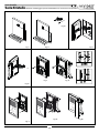
Kristallo Series 3.5" ush and surface videomonitor wall mounting instructions
135cm
135cm
Fig. 1 Fig. 1a
Fig. 2a
Fig. 4
Fig. 4a Fig. 4b
Fig. 3 Fig. 3a
Fig. 1b
Fig. 2

66250900 - V4.1 - 15/05/19
- 7 -
Kristallo Series
Art.KRV76-KRV78 - Installation instructions
Kristallo Series 3.5" Flush and surface videomonitor wall mounting instructions
FLUSH MOUNT KRISTALLO VIDEOPHONE
1. Protect the holes to x the videophone to the ush mounting box then embed the ush mounting box in line with the wall in a
vertical position at 135cm height from the oor as shown in Fig. 1.
2. As shown in Fig. 2, connect the wires using a at screw driver then setup the dip-switches as per provided connection diagram
or instruction sheet.
3. As shown in Fig. 3, once the wires are connected, x the videophone to the ush mounting box using a Phillips screwdriver and
the two screws provided.
In order to avoid malfunctions, please do not over tighten the xing screws shown in Fig. 3.
4. Once the videophone is xed to the ush mounting box, place the front plate against the videophone by inserting the hooks in
the corresponding openings and hook the plate by pushing it down as shown in Fig. 4.
5. Test the system for correct operation.
SURFACE MOUNT KRISTALLO VIDEOPHONE
1. As shown in Fig. 1a, place the videophone against the wall at 135cm height from the oor and mark the xing holes. Make the
holes (5mm diameter) and insert the provided wall plugs as shown in Fig. 1b.
2. As shown in Fig. 2a, connect the wires using a at screw driver then setup the dip-switches as per provided connection diagram
or instruction sheet.
3. As shown in Fig. 3a, once the wires are connected, x the videophone to the wall using a Phillips screwdriver and the two screws
provided.
In order to avoid malfunctions, please do not over tighten the xing screws shown in Fig. 3a.
4. Once the videophone is xed to the wall, place the front plate against the videophone by inserting the hooks in the correspond-
ing openings and hook the plate by pushing it down as shown in Fig. 4a and hang the handset as shown in Fig. 4b.
5. Test the system for correct operation.
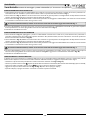
TOUCH SENSITIVE KEYS ADJUSTMENT
Cleansing the panel with the plate on or removing the plate for any reason may cause the touch sensitive buttons to lose their ad-
justment. If you detect any malfunctions, we suggest you proceed as follows:
• Remove the front plate doing the contrary of what is shown in Fig. 4 and Fig. 4a;
• Touch the touch sensitive
button area (the rst of the three areas aligned in horizontal way from the right side)until the display
turns on (about 5 seconds);
• Touch the touch sensitive button area repeatedly until the pointer is on “EXIT”;
• Hang up the front plate as shown in picture Fig. 4 and Fig. 4a; before the display turns o;
• When the display turns o the setting is done and the system is ready for use.

66250900 - V4.1 - 15/05/19
- 8 -
Serie Kristallo
Art.KRV76-KRV78 - Istruzioni di installazione
Art.KRV76-KRV78
Videocitofoni vivavoce Serie Kristallo per sistemi con segnale video composito (coassiale) o bialnciato (2 li)
112 42
155
182
29
A
B
E
F
C
D
Fig. 1
Art.KRV76 fronte
120
190
839
189
119
A
B
E
C
D
Fig. 2
Art.KRV78 fronte
DOL
SB
AL
LB
L
_
12Vin
12Vout
GND
V2/V
V1
+20
+VD
RS-232
ON ON
SW2
SW1
G
I
L
H
Fig. 3
Art.KRV78 retro
DESCRIZIONE
Videocitofono vivavoce intelligente specico per il sistema
VX2200 con monitor a colori OSD LCD TFT da 3,5”, pulsanti tou-
ch sensitive con funzione di “apri-porta/chiamata a portiere”,
“risposta/auto-accensione”, “privacy/servizio” più 5 pulsanti per
la navigazione nei menù di regolazione e programmazione e 3
LED* relativi al funzionamento del videocitofono. Nella versione
da supercie, Art.KRV76, è presente anche la cornetta per l’uti-
lizzo convenzionale in aggiunta alla modalità vivavoce. I videocitofoni della linea Kristallo sono dotati anche di orologio real-time e
sensore di temperatura nonché di una porta seriale per eventuali utilizzi in ambito domotico. Regolazioni e programmazioni riser-
vate all’utente vengono eettuate tramite l’ausilio dei pulsanti di navigazione e di un menù OSD. Tra le regolazioni sono presenti:
• Volume del tono di chiamata (3 livelli);
• V olume della fonia (8 livelli);
• Luminosità (8 livelli);
• Contrasto (8 livelli);
• Saturazione (8 livelli).
Mentre tra le programmazioni troviamo:
• Data e ora;
• Durata privacy (da 30 minuti a 20 ore o illimitata);
• Suoneria (9 disponibili);
• Numero di squilli (da 1 a 9).
L’indirizzo del videocitofono e il modo video vengono impostati rispettivamente tramite il dip-switch ad 8 vie e quello a 4 vie pre-
senti sul retro del dispositivo.
Nota elettronica oerta dal sistema più ingressi attivo bassi per chiamata locale ed allarme.
LEGENDA
A
Microfono
B
Display
C
Pulsanti e LED operativi
D
Pulsanti di navigazione e
regoalzione
E
Altoparlante
F
Cornetta
G
Morsettiera di connessione
H
Porta Seriale RS-232
I
Dip-switch ad 4 vie
L
Dip-switch ad 8 vie
Rev.1.0

66250900 - V4.1 - 15/05/19
- 9 -
Serie Kristallo
Art.KRV76-KRV78 - Istruzioni di installazione
PULSANTI E REGOLAZIONI
• Alla ricezione della chiamata, abilita l’inizio conversazione. Il relativo LED si accende.
• Ad impianto spento, premere il pulsante tante volte quant’è il valore dell’identicativo del posto esterno da accendere.
Il relativo LED si accende.
• Ad impianto acceso, consente lo spegnimento manuale (rapida pressione del tasto). In ogni caso lo spegnimento è
automatico (il relativo LED si spegne) allo scadere del tempo di conversazione.
• Premendo il pulsante per più di 2 secondi, il videocitofono passa nel modo trasmissione ad una via: per parlare con
l’esterno occorre tenere premuto il pulsante (il LED lampeggia rapidamente), mentre per ascoltare il visitatore occorre
lasciare il pulsante (il LED lampeggia lentamente). Trascorsi 10 secondi senza premere nuovamente il pulsante, il siste-
ma si spegne. Il videocitofono torna al funzionamento normale alla successiva accensione.
• A sistema acceso, apre la porta. L’apertura è indicata da un segnale acustico e dalla comparsa del relativo simbolo
nella parte superiore dello schermo sotto alla riga che riporta data ora e temperatura. Se il relativo morsetto è stato
opportunamente collegato, il LED sopra al pulsante chiave resterà acceso per tutto il tempo che la porta resta aperta.
• A sistema spento, eettua la chiamata al centralino di portineria se presente nell’impianto.
• Con il sistema in stand-by, premere per attivare il servizio privacy per il tempo programmato: il relativo LED si accende
a segnalare lo stato di attivazione del servizio. All’arrivo della chiamata, con il servizio attivo, l’unità non emette alcun
segnale acustico. Il servizio si disattiva allo scadere del tempo programmato o premendo nuovamente il pulsante.
• Con il sistema in stand-by, tenere premuto il pulsante no a che il monitor non si accende mostrando il menù di
programmazione data e ora, durata privacy, volume tono di chiamata, suoneria e numero di squilli. Procedere ai vari
settaggi utilizzando gli appositi pulsanti di navigazione menù.
• Durante la ricezione della chiamata, premere questo pulsante per riutare la chiamata senza dare alcuna segnalazione
all’esterno.
• Durante la conversazione, premere e tenere premuto questo pulsante no a che il videocitofono non emette un se-
gnale acustico visualizzando il simbolo “SRV” nella parte superiore dello schermo sotto alla riga che riporta data ora e
temperatura.: l’uscita ausiliaria viene attivata e il morsetto SB chiude verso massa per circa 2 secondi.
• Durante la conversazione, premere questo pulsante per accedere al menù di regolazione del volume fonia, della luminosità,
contrasto e saturazione immagine. Attivato il menù, procedere alle regolazioni tramite i pulsanti di navigazione menù.
Pulsanti di navigazione per i menù di regolazione e programmazione. Tramite questi pulsanti è possibile impostare la
data e l’ora, la suoneria, il numero di squilli, la durata della privacy e regolare i volumi della fonia e della nota di chiamata
nonché la luminosità, il contrasto e la saturazione dell’immagine.
Quando il sistema è in stand-by (monitor spento), questo pulsante permette di intercomunicare con gli altri interni.
Premere un numero di volte pari all'indirizzo (PHONE ID) o all'indirizzo di interno (EXT.ID) del videocitofono da chiamare
(indirizzo o interno dipende dal tipo di intercomunicazione).
FUNZIONAMENTO
RICEZIONE DI UNA CHIAMATA
Durante la chiamata il display si accende mostrando la
schermata a anco ed è possibile:
• Rispondere in modalità viva-voce premendo il pul-
sante
Fig.1A (o sollevando la cornetta per il mo-
dello Art.KRV76);
• Aprire la porta senza parlare al visitatore premendo il
pulsante Fig.1B;
• Riutare la chiamata premendo il pulsante senza
che il visitatore riceva alcuna segnalazione Fig1C.
15/12/11 14.5°C 09:23
Fig.1
15/12/11 14.5°C 09:23
MENU
PT T
Fig.1A
15/12/11 14.5°C 09:23
MENU
PT T
Fig.1B Fig.1C
Art.KRV78-KRV76
Videocitofoni vivavoce Serie Kristallo per sistemi con segnale video composito (coassiale) o bialnciato (2 li)

66250900 - V4.1 - 15/05/19
- 10 -
Serie Kristallo
Art.KRV76-KRV78 - Istruzioni di installazione
DURANTE LA CONVERSAZIONE
Durante la conversazione Fig.2 è possibile:
• Passare dalla modalità vivavoce alla modalità “push to
talk” (premi per parlare) tenendo premuto il pulsante
no a che il relativo LED non inizia a lampeggiare
lentamente Fig.2A. Tenere premuto il pulsante
(il
LED lampeggia velocemente) per parlare con il visita-
tore, rilasciare il pulsante (il LED lampeggia lentamen-
te) per ascoltare il visitatore;
• Aprire la porta premendo il pulsante Fig.2B;
• Attivare il servizio secondario tenendo premuto il pul-
sante
no alla segnalazione di attivazione Fig.2C;
• Per passare dai gradi Celsius o Fahrenheit e viceversa,
premere il pulsate .
• Attivare il menù delle regolazioni premendo il pulsan-
te
Fig.3.
15/12/11 14.5°C 09:23
MENU
PT T
Fig.2
15/12/11 14.5°C 09:23
PT T
Fig.2A
15/12/11 14.5°C 09:23
MENU
PT T
Fig.2B
15/12/11 14.5°C 09:23
M ENU
PT T
SRV
Fig.2C
MENÙ DELLE REGOLAZIONI
Nel menù delle regolazioni è possibile impostare:
• Il volume della fonia (8 livelli Fig.3);
• La luminosità (8 livelli Fig.3A);
• Il contrasto (8 livelli Fig.3B);
• La saturazione (8 livelli Fig.3C);
Impostare la regolazione selezionata agendo sui
pulsanti
e quindi confermare premendo per
passare alla regolazione successiva o premendo o
per muoversi tra le varie regolazioni.
Selezionato “EXIT”, premere per uscire dal EXIT menù
o per tornare variare delle impostazioni.
PROGRAMMAZIONE PARAMETRI
La programmazione consiste in una serie di settaggi che
in parte vengono eseguiti tramite menù OSD ed in parte
tramite l’impostazione manuale dei due banchi dip-switch
accessibili nella parte posteriore del videocitofono.
OSD
EXIT
Fig.3
OSD
EXIT
Fig.3A
OSD
EXIT
Fig.3B
OSD
EXIT
Fig.3C
Art.KRV78-KRV76
Videocitofoni vivavoce Serie Kristallo per sistemi con segnale video composito (coassiale) o bialnciato (2 li)

66250900 - V4.1 - 15/05/19
- 11 -
Serie Kristallo
Art.KRV76-KRV78 - Istruzioni di installazione
MENÙ PROGRAMMAZIONI
Con il sistema in stand-by, tenere premuto il pulsante
no a che il monitor non si accende mostrando la scher-
mata di anco.
La prima programmazione è relativa a data e ora Fig.4:
• alterare il valore agendo sui pulsanti
e ;
• utilizzare i pulsanti e per spostarsi tra i campi
da impostare (giorno, mese, anno, ore e minuti);
• confermare l’impostazione premendo o premen-
do il pulsante sulla selezione dei minuti. Il menù
passa alla programmazione successiva.
La seconda impostazione riguarda la durata della
privacy Fig.4A (da 0 a 20 ore):
• alterare il valore a passi di 30 minuti tramite i pulsanti
e (0 = durata illimitata, il servizio si disattiva solo
premendo nuovamente il pulsante );
• confermare il valore impostato tramite il pulsante
o il pulsante . L’impostazione passa alla program-
mazione successiva.
Procedere analogamente per le altre programmazioni:
volume nota di chiamata (3 livelli Fig.4B), suoneria (9
opzioni Fig.4C), numero di squilli (da 1 a 9 Fig.4D) e du-
rata pulsante di servizio (0 o da 1 a 99 secondi Fig.4E da
versione rmware 2.3 e successive).
La “durata del pulsante di servizio” ha una programma-
zione speciale:
• da 1 a 99 secondi determina la durata dell’attivazione
dell’uscita “SB” quando viene attivato il servizio.
• Impostando il valore 0, il servizio funziona in 2 modi:
1. Con il videocitofono in stand-by, l’uscita “SB” si at-
tiva automaticamente per circa 30 secondi a seguito di una chiamata “local bell” (ingresso “LB”);
2. Con il videocitofono accesso, quando si attiva normalmente il “servizio”, l’uscita “SB” si abilita per circa 20 secondi.
L’ultima impostazione riguarda il modo di intercomunicazione “IC” (da versione rmware 3.0 e successive). Due sono i modi di inter-
comunicazione disponibili:
• Per impostare l’intercomunicazione tra appartamenti
(videocitofoni con diverso indirizzo/PHONE ID) pre-
mere il pulsante
no a selezionare “APT. MODE”
(Fig.4F). In stand-by, premendo il pulsante una
o più volte sarà possibile chiamare i videcitofoni con
indirizzo/PHONE ID da 1 a 9.
• Per impostare l’intercomunicazione tra interni dello
stesso appartamento (videocitofoni con stesso indi-
rizzo/PHONE ID ma con dierente interno/EXT. ID) se-
lezionare un indirizzo di interno/EXTENSION ID com-
preso ta 1 e 9 (Fig.4G) premendo i pulsanti o . In
stand-by, premendo il pulsante una o più volte sarà possibile chiamare i videcitofoni con interno/EXT ID da 1 a 9.
Una volta selezionato “EXIT”, premere
per uscire o il pulsante per tornare a variare le programmazioni.
NOTA
Da qualsiasi menù OSD, se il monitor si spegne per timeout, le regolazioni e le programmazioni eettuate non vengono memorizzate.
09:2315/12/11
EXIT
Fig.4
01 . 5h
EXIT
Fig.4A
EXIT
Fig.4B
RINGS 6
EXIT
Fig.4D
MEL ODY 1
EXIT
Fig.4C
02 SEC
EXIT
Fig.4E
APT.MODE
EXIT
Fig.4F
EXT. ID: 2
EXIT
Fig.4G
Art.KRV78-KRV76
Videocitofoni vivavoce Serie Kristallo per sistemi con segnale video composito (coassiale) o bialnciato (2 li)

66250900 - V4.1 - 15/05/19
- 12 -
Serie Kristallo
Art.KRV76-KRV78 - Istruzioni di installazione
MODO VIDEO SW2
La modalità video viene impostata tramite il Dip-Switch a 4
vie accessibile dalla parte posteriore del blocco superiore del
videocitofono.
Gli switch 3 e 4 servono ad adattare l’impedenza del
segnale video; in caso di più videocitofoni collegati in
parallelo, devono essere impostati entrambi ad OFF per
tutti i videocitofoni ad eccezione dell’ultimo in ordine di
collegamento.
MODO VIDEO
Switch 1,2 Modo
ON
1 32 4
Coassiale
ON
1 32 4
Bilanciato
TERMINAZIONE VIDEO 75 OHM
Switch 3,4 Terminazione
ON
1 32 4
Attiva
ON
1 32 4
Disattiva
IMPOSTAZIONE INDIRIZZO VIDEOCITOFONO SW1
L’indirizzo del videocitofono è codicato in binario tramite il dip-switch ad 8 vie situato al suo interno. Ogni switch corrisponde ad
un bit che può essere a 0 (OFF) o 1 (ON), a ciascun bit corrisponde un peso decimale in base alla posizione: per impostare l’indirizzo
desiderato, mettere ad ON (1) gli switch la cui somma dei pesi corrisponde al valore dell’indirizzo. Ad esempio, per impostare l’indi-
rizzo 37, mettere ad ON gli switch 1, 3 e 6 (1+4+32=37).
SWITCH PESO DECIMALE INDIRIZZO
8 7 6 5 4 3 2 1 128 64 32 16 8 4 2 1
OFF OFF OFF OFF OFF OFF OFF ON 0 0 0 0 0 0 0 1 1
OFF OFF OFF OFF OFF OFF ON OFF 0 0 0 0 0 0 1 0 2
OFF OFF OFF OFF OFF OFF ON ON 0 0 0 0 0 0 1 1 3
OFF OFF OFF OFF OFF ON OFF OFF 0 0 0 0 0 1 0 0 4
OFF OFF ON OFF OFF ON OFF ON 0 0 1 0 0 1 0 1 37
ON OFF ON ON OFF ON OFF OFF 1 0 1 1 0 1 0 0 180
SEGNALI MORSETTIERA DI CONNESSIONE
DOL Ingresso +12Vdc per LED “door open”
SB
Uscita open collector pulsante di servizio (tipo at-
tivo basso). Con il monitor acceso, si attiva tenen-
do premuto il pulsante
no a che no si abilita il
servizio. L’uscita resta attiva per circa 2 secondi.
AL
Ingresso attivo basso per segnale di allarme. Quando
attivo, il sistema invia l’allarme al centralino di port-
ineria se presente e attiva l’Art.512DR se presente ed
opportunamente congurato.
LB Ingresso attivo basso per chiamata di piano “Local Bell”.
L Ingresso linea dati BUS.
— Ingresso massa linea BUS.
12Vin Ingresso +12Vdc di alimentazione in stand-by.
12Vout Uscita stabilizzata +12Vdc
GND
Ingresso massa di alimentazione / massa segnale vi-
deo coassiale
V2/V
Sincronia V2 segnale video bilanciato (modo seg. video bil.)
Segnale video composito (modo segnale video coassiale)
V1 Sincronia V1 segnale video bilanciato
+20 Ingresso di alimentazione +20Vdc
+VD
Uscita 12Vdc per alimentazione distributore video
Art.894/Art.894N
NOTE
Quando si fa il ponte tra 12Vin e 12Vout, un Art.893N1 addizio-
nale è necessario ogni 50 videocitofoni presenti nel sistema..
SPECIFICHE TECNICHE
Tensioni d’alimentazione: 17÷20Vdc
12÷14Vdc
Assorbimenti: 6mA in stand-by (on 12Vdc)
200mA Max (su 12Vdc)
250mA Max (su 20Vdc)
Temperatura di lavoro: -10°C +50°C
MEMORIA VIDEO
Questo dispositivo è disponibile an-
che nella versione con memoria video
(Art.KRV76/VM e Art.KRV78/VM).
Se si è in possesso di questa versione, si prega
di consultare il manuale utente “Memoria
video Serie Kristallo 3,5"” (in inglese e
italiano) per l’installazione e l’utilizzo.
Il manuale è disponibile per il download: cliccare, fare tap o
scansionare il codice QR.
Art.KRV78-KRV76
Videocitofoni vivavoce Serie Kristallo per sistemi con segnale video composito (coassiale) o bialnciato (2 li)

66250900 - V4.1 - 15/05/19
- 13 -
Serie Kristallo
Art.KRV76-KRV78 - Istruzioni di installazione
Serie Kristallo Istruzioni di montaggio a parete videocitofoni 3,5" da incasso e da supercie
135cm
135cm
Fig. 1 Fig. 1a
Fig. 2a
Fig. 4
Fig. 4a Fig. 4b
Fig. 3 Fig. 3a
Fig. 1b
Fig. 2

66250900 - V4.1 - 15/05/19
- 14 -
Serie Kristallo
Art.KRV76-KRV78 - Istruzioni di installazione
Serie Kristallo Istruzioni di montaggio a parete videocitofoni 3,5" da incasso e da supercie
VIDEOCITOFONI KRISTALLO DA INCASSO
1. Proteggendo i fori di ssaggio del videocitofono alla scatola da incasso, murare a lo muro la scatola da incasso in posizione ver-
ticale lasciando circa 135cm tra la parte inferiore della scatola e il pavimento come mostrato in Fig. 1;
2. Come mostrato in Fig. 2, eettuare le connessioni con l’ausilio di un giravite piatto e le congurazioni dei dip-switches come da
schema di collegamento fornito a corredo o come da foglio di istruzioni;
3. Come mostrato in Fig. 3, eettuate tutte le connessioni, procedere al ssaggio del videocitofono alla scatola da incasso tramite
le 2 viti fornite a corredo con l’ausilio di un giravite a croce;
Per evitare malfunzionamenti, evitare di serrare eccessivamente le viti di ssaggio mostrata nella Fig. 3.
4. Fissato il videocitofono alla scatola da incasso, avvicinare la placca frontale al videocitofono inserendo i 4 ganci nelle rispettive
fessure quindi ssare la stessa spingendola verso il basso come mostrato in Fig. 4;
5. Procedere al collaudo del sistema.
VIDEOCITOFONI KRISTALLO DA SUPERFICIE
1. Come mostrato in Fig. 1a, appoggiare a parete il videocitofono lasciando circa 135cm tra la parte inferiore ed il pavimento e
prendere i riferimenti per i fori di ssaggio a parete. Realizzare i fori (diametro 5mm) ed inserire all’interno i tasselli ad espansione
forniti a corredo come mostrato in Fig. 1b;
2. Come mostrato in Fig. 2a, eettuare le connessioni con l’ausilio di un giravite piatto e le congurazioni dei dip-switches come da
schema di collegamento fornito a corredo o come da foglio di istruzioni;
3. Come mostrato in Fig. 3a, eettuate tutte le connessioni, procedere al ssaggio del videocitofono alla scatola da incasso tramite
le 2 viti fornite a corredo con l’ausilio di un giravite a croce;
Per evitare malfunzionamenti, evitare di serrare eccessivamente le viti di ssaggio mostrata nella Fig. 3.
4. Fissato il videocitofono a parete, avvicinare la placca frontale al videocitofono inserendo i 4 ganci nelle rispettive fessure quindi
ssare la stessa spingendola verso il basso come mostrato in Fig. 4a e agganciare la cornetta come mostrato in Fig. 4b;
5. Procedere al collaudo del sistema.
TARATURA DEI TASTI TOUCH SENSITIVE
La pulizia con la placca montata o la rimozione della stessa per un qualunque motivo, potrebbero causare la staratura dei pulsanti
touch sensitive. Qualora venissero rilevate delle anomalie di funzionamento, si suggerisce di procedere come segue:
• Rimuovere la placca frontale procedendo al contrario di come mostrato nelle Fig. 4 e Fig. 4a;
• Toccare la piazzola relativa al tasto
(la prima da destra delle tre allineate in orizzontale) no all’accensione del display (circa 5 secondi);
• Toccare più volte la piazzola relativa al tasto no a che il cursore si posiziona su “EXIT”;
• Agganciare la placca come mostrato nelle Fig. 4 e Fig. 4a prima che si spenga il display;
• Quando il display si spegne la taratura è avvenuta e il sistema è pronto all’utilizzo.

66250900 - V4.1 - 15/05/19
- 15 -

66250900 - V4.1 - 15/05/19
- 16 -

66250900 - V4.1 - 15/05/19
- 17 -

66250900 - V4.1 - 15/05/19
- 18 -

66250900 - V4.1 - 15/05/19
- 19 -
DISPOSAL
In accordance with the Legislative Decree no. 49 of 14 March 2014 “Implementation of the Directive 2012/19/EU on
waste electrical and electronic equipment (WEEE)”.
The crossed-out bin symbol on the equipment or on the packaging indicates that when the product reaches the end
of its lifetime, it must be collected separately from mixed municipal waste. The user must, therefore, dispose of the
equipment at the end of its lifetime in the suitable waste collection centres or bring it to the retailer during the pur-
chase of a new equipment of equivalent type at the ratio of one-to-one. Furthermore, the user is allowed to dispose
of the WEEEs of very small size (domestic appliances without any external dimension exceeding 25 cm (9.84 inches)
for free to the retailers, without any purchase obligation. The correct waste disposal of the WEEEs contributes to their
reuse, recycling and recovery and avoids potential negative eects on the environment and human health due to the
possible presence of dangerous substances within them.
SMALTIMENTO
Ai sensi del Decreto Legislativo 14 marzo 2014, n° 49 “Attuazione della direttiva 2012/19/UE sui riuti di apparecchia-
ture elettriche ed elettroniche (RAEE)”.
Il simbolo del cassonetto barrato riportato sull’apparecchiatura o sulla sua confezione indica che il prodotto alla ne
della propria vita utile deve essere raccolto separatamente dagli altri riuti urbani misti. L’utente dovrà, pertanto, con-
ferire l’apparecchiatura giunta a ne vita presso gli idonei centri di raccolta dierenziata oppure riconsegnarla al riven-
ditore al momento dell’acquisto di una nuova apparecchiatura di tipo equivalente, in ragione di uno a uno. L’utente ha,
inoltre, la possibilità di conferire gratuitamente presso i distributori, senza alcun obbligo di acquisto, per i RAEE di pic-
colissime dimensioni (per le apparecchiature di tipo domestico con nessuna dimensione esterna superiore a 25 cm).
L’adeguata raccolta dierenziata dei RAEE contribuisce al loro riutilizzo, riciclaggio e recupero ed evita potenziali ef-
fetti negativi sull’ambiente e sulla salute umana dovuti alla eventuale presenza di sostanze pericolose al loro interno.
ÉLIMINATION
Conformément au décret législatif n ° 49 du 14 mars 2014 relatif à l’«Application de la directive 2012/19 / UE relative
aux déchets d’équipements électriques et électroniques (DEEE)».
Le symbole de la poubelle barrée sur l’équipement ou sur son emballage indique que le produit en n de vie utile doit être
collecté séparément des autres déchets municipaux en mélange. L’utilisateur doit donc remettre l’équipement en n de
vie aux centres de collecte appropriés ou le restituer au revendeur lors de l’achat d’un nouveau type d’équipement équiva-
lent, dans le rapport de un à un. De plus, l’utilisateur a la possibilité de conférer gratuitement aux distributeurs, sans aucune
obligation d’achat, de très petits DEEE (pour les appareils ménagers sans dimensions extérieures supérieures à 25 cm).
La collecte séparée adéquate des DEEE contribue à leur réutilisation, leur recyclage et leur valorisation et évite les
éventuels eets négatifs sur l’environnement et la santé humaine en raison de la présence possible de substances
dangereuses dans ceux-ci.
ELIMINACIÓN
De conformidad con el Decreto legislativo n. 49 de 14 de marzo 2014 “Aplicación de la Directiva 2012/19/UE relativa a
residuos de aparatos eléctricos y electrónicos (RAEE)”.
El símbolo del contenedor tachado indicado sobre los aparatos o sobre los embalajes señala que el producto al -
nal de su vida útil debe ser recogido separadamente de otros residuos municipales mezclados. Por tanto, el usuario
deberà conferir los aparatos al nal de su vida útil en los apropriados centros de recogida selectiva o devolverlos al
revendedor al momento de la compra de nuevos aparatos equivalentes, en una relación de uno a uno. Además, el
usuario tiene la posibilidad de entregar sin cargo a los distribuidores, sin ninguna obligación de compra, los RAEEs
muy pequeños (para electrodomésticos sin dimensiones externas superiores a 25 cm).
La recogida selectiva apropriada de los RAEEs contribuye a su reutilización, reciclaje y valorización y evita potenciales
impactos negativos sobre el medio ambiente y la salud humana debidos a la possible presencia de substancias peli-
grosas dentro de ellos.
VERWIJDERING
In overeenstemming met het Wetsbesluit nr. 49 van 14 maart 2015 “Implementatie van de Richtlijn 2012/19/EU inzake
afgedankte elektrische en elektronische apparaten (AEEA)”.
Het doorgekruiste vuilnisbaksymbool op het apparaat of de verpakking geeft aan dat het product aan het einde van
zijn levensduur niet samen met het gewone huisvuil weggegooid mag worden. De gebruiker moet het apparaat aan
het einde van zijn levensduur inleveren bij een gepast inzamelpunt of de winkel waar hij een nieuw apparaat van een
gelijksoortig type zal kopen. De gebruiker kan tevens AEEA’s van een zeer klein formaat (huishoudapparaten met een
buitenafmeting kleiner dan 25 cm (9,84 inch)) gratis en zonder enige aankoopverplichting bij handelaars inleveren.
Een juiste verwijdering van AEEA’s draagt bij tot hergebruik, recycling en terugwinning, en voorkomt potentiële ne-
gatieve eecten op het milieu en de menselijke gezondheid door de mogelijke aanwezigheid van gevaarlijke stoen.

MANUFACTURER
FABBRICANTE
FABRICANT
FABRICANTE
FABRIKANT
ةع
نصملا ةكرشلا
VIDEX ELECTRONICS S.P.A.
Via del Lavoro, 1
63846 Monte Giberto (FM) Italy
Tel (+39) 0734 631669
Fax (+39) 0734 632475
www.videx.it - inf[email protected]
CUSTOMER SUPPORT
SUPPORTO CLIENTI
SUPPORTS CLIENTS
ATENCIÓN AL CLIENTE
KLANTENDIENST
ءمعلا ةمدخ
VIDEX ELECTRONICS S.P.A.
www.videx.it - technical@videx.it
Tel: +39 0734-631669
Fax: +39 0734-632475
UK Customers only:
VIDEX SECURITY LTD
www.videxuk.com
Tech Line: 0191 224 3174
Fax: 0191 224 1559
Main UK oce:
VIDEX SECURITY LTD
1 Osprey Trinity Park
Trinity Way
LONDON E4 8TD
Phone: (+44) 0870 300 1240
Fax: (+44) 020 8523 5825
www.videxuk.com
Northern UK oce:
VIDEX SECURITY LTD
Unit 4-7
Chillingham Industrial Estate
Chapman Street
NEWCASTLE UPON TYNE - NE6 2XX
Tech Line: (+44) 0191 224 3174
Phone: (+44) 0870 300 1240
Fax: (+44) 0191 224 1559
Greece oce:
VIDEX HELLAS Electronics
48 Filolaou Str.
11633 ATHENS
Phone: (+30) 210 7521028
(+30) 210 7521998
Fax: (+30) 210 7560712
www.videx.gr
Danish oce:
VIDEX DANMARK
Hammershusgade 15
DK-2100 COPENHAGEN
Phone: (+45) 39 29 80 00
Fax: (+45) 39 27 77 75
www.videx.dk
Benelux oce:
NESTOR COMPANY NV
E3 laan, 93
B-9800 Deinze
Phone: (+32) 9 380 40 20
Fax: (+32) 9 380 40 25
www.videx.be
Dutch oce:
NESTOR COMPANY BV
Business Center Twente (BCT)
Grotestraat, 64
NL-7622 GM Borne
www.videxintercom.nl
info@videxintercom.nl
El producto lleva la marca CE que demuestra su conformidad y puede ser
distribuido en todos los estados miembros de la unión europea UE.
Este producto cumple con las Directivas Europeas 2014/30/EU (EMC);
2014/35/EU (LVD); 2011/65/EU (RoHS): marca CE 93/68/EEC.
Het product heeft de CE-markering om de conformiteit ervan aan te tonen en
is bestemd voor distributie binnen de lidstaten van de EU zonder beperkin-
gen. Dit product volgt de bepalingen van de Europese Richtlijnen 2014/30/EU
(EMC); 2014/35/EU (LVD); 2011/65/EU (RoHS): CE-markering 93/68/EEG.
Le produit est marqué CE à preuve de sa conformité et peut être distribué
librement à l’intérieur des pays membres de l’union européenne EU.
Ce produit est conforme aux directives européennes 2014/30/EU (EMC) ;
2014/35/EU (LVD) ; 2011/65/EU (RoHS): marquage CE 93/68/EEC.
The product is CE marked demonstrating its conformity and is for distribution
within all member states of the EU with no restrictions. This product follows
the provisions of the European Directives 2014/30/EU (EMC); 2014/35/EU
(LVD); 2011/65/EU (RoHS): CE marking 93/68/EEC.
Il prodotto è marchiato CE a dimostrazione della sua conformità e può essere
distribuito liberamente all’interno dei paesi membri dell’Unione Europea UE.
Questo prodotto è conforme alle direttive Europee: 2014/30/UE (EMC);
2014/35/UE (LVD); 2011/65/UE (RoHS): marcatura CE 93/68/EEC.
CE
EU/2014/30
:(RoHS(EMC); 2014/35/EU (LVD); 2011/65/EU
.CE 93/68/EEC
-
 1
1
-
 2
2
-
 3
3
-
 4
4
-
 5
5
-
 6
6
-
 7
7
-
 8
8
-
 9
9
-
 10
10
-
 11
11
-
 12
12
-
 13
13
-
 14
14
-
 15
15
-
 16
16
-
 17
17
-
 18
18
-
 19
19
-
 20
20


Videx Security KRV7X Owner's manual
- Category
- Door intercom systems
- Type
- Owner's manual
Ask a question and I''ll find the answer in the document
Finding information in a document is now easier with AI
in other languages
Related papers
-
Videx KRV772W Owner's manual
-
-
Videx Security 3371 Owner's manual
-
-
-
-
-
-
-
Other documents
-
Auta 701812 NEOS HANDSET - DIGITAL 4W User manual
-
-
-
-
-
-
-
-
nestor cables Termination Box 4 User manual
-