Metabo Mega 450 W Operating instructions
- Category
- Air compressors
- Type
- Operating instructions

115 168 4480 / 0310 - 3.0
Mega 450 W
Originalbetriebsanleitung. . . . . . . . . . . . . . .3
Original operating instructions . . . . . . . . . .10
Instructions d’utilisation originales . . . . . . .16
Origineel gebruikaanwijzing. . . . . . . . . . . .23
Manuale d’uso originale. . . . . . . . . . . . . . .30
Manual de instrucciones original . . . . . . . .37
Original brugsvejledning . . . . . . . . . . . . . .44
Original bruksanvisning . . . . . . . . . . . . . . .50
Alkuperäiskäyttöohje . . . . . . . . . . . . . . . . .56
K0048_30IVZ.fm
Page is loading ...
Page is loading ...
Page is loading ...
Page is loading ...
Page is loading ...
Page is loading ...
Page is loading ...
Page is loading ...

10
ENGLISH
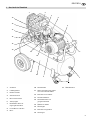
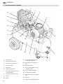
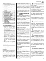
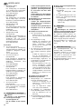
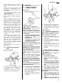
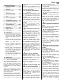
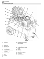
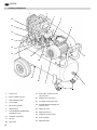
1. Machine overview
12
5
6
4
8
9
12
14
15
16
3
11
7
17
18
19
10
13
1 Compressor pump
2 Air intake filter housing
3 On/Off switch
4 Safety valve
5 Motor protection
6 Transport handle
7 Outlet for unregulated com-
pressed air
8 Swivel plate casters, lockable
9 Motor
10 Pressure vessel
11 Condensate drain cock of pres-
sure vessel
12 Tank pressure gauge
13 Filter/Regulator unit
14 Outlet for regulated com-
pressed air
15 Oil drain plug
16 Oil sight glass
17 Outlet pressure gauge
18 Pressure regulator
19 Oil filler plug
XK0024E.fm Operating Instruction ENGLISH

11
ENGLISH
1. Machine overview .....................10
2. Please read first!.......................11
3. Safety .........................................11
3.1 Specified conditions of use .........11
3.2 General safety information..........11
3.3 Safety devices ............................12
4. Operation...................................12
4.1 Prior to initial operation...............12
4.2 Generating compressed air ........ 12
5. Care and maintenance .............12
5.1 Periodic maintenance .................12
5.2 Device storage............................13
6. Available Accessories......... 13/63
7. Trouble shooting ......................14
8. Repairs.......................................15
9. Environmental protection ........15
10. Technical specifications ..........15
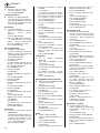
• Read these instructions before use.
Pay special attention to the safety
information.
• If you notice transport damage while
unpacking, notify your supplier
immediately. Do not operate the
device!
• Dispose of the packing in an envi-
ronmentally friendly manner. Take
to a proper collecting point.
• Keep these instructions for refer-
ence on any issues you may be
uncertain about. Also keep the test
certificates of all compressed air
components.
• If you lend or sell this device be sure
to have the instructions to go with it.
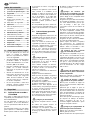
3.1 Specified conditions of use
This device is intended to generate com-
pressed air required for the operation of
air tools.
Any use for medical purposes, food
processing as well as filling of oxygen
cylinders for breathing equipment is not
permitted.
Explosive, combustible gases or gases
detrimental to health may not be com-
pressed. Operation in hazardous loca-
tions is not permitted.
Any other use is not as specified. Use
not as specified, alteration of the device
or use of parts not approved by the
equipment manufacturer, can cause
unforeseeable damage!
Children, juveniles and persons not hav-
ing been instructed in its usage are not
permitted to operate this device and any
air tools connected to it.
3.2 General safety informa-
tion
When using this electric tool observe the
following safety instructions, to exclude
the risk of personal injury or material
damage.
Please also observe the special safety
instructions in the respective chapters.
Keep all documents, supplied with the
device, for future reference.
Observe the statuary accident insurance
institution regulations and regulations for
the prevention of accidents pertaining to
the operation of air compressors and air
tools, where applicable.
A
General hazard!
Keep your work area tidy – a messy
work area invites accidents.
Be alert. Know what you are doing. Set
out to work with reason. Do not operate
the electric tool while under the influence
of drugs, alcohol or medication.
Consider environmental conditions.
Keep work area well lighted.
Prevent adverse body positions. Ensure
firm footing and keep your balance at all
times.
Do not operate the electric tool near
inflammable liquids or gases.
Keep bystanders, particularly children,
out of the work area. Do not permit other
persons to touch the tool or power cable
while the electric tool is running.
Do not overload the electric tool – use it
only within the performance range it was
designed for (see Technical specifica
-
tions).
B
Danger! Risk of electric shock!
Do not expose the electric tool to rain.
Do not operate the electric tool in damp
or wet environment.
Prevent body contact with earthed
objects such as radiators, pipes, cooking
stoves or refrigerators when operating
this electric tool.
Do not use the power cable for any pur-
pose it is not intended for.
A
Risk of personal injury by
escaping compressed air and parts
hurled about by escaping air!
Never direct compressed air against per-
sons or animals!
Ensure all air tools and accessories
used are designed for the working pres
-
sure or are supplied via a pressure regu-
lator.
Please note that, when disconnecting
the quick coupler, the compressed air
contained in the pressure hose will
escape all of a sudden. You should
therefore hold the air hose firmly when
disconnecting it.
Ensure all screwed connections are fully
tightened at all times.
Do not attempt to repair the device your-
self! Only trained specialists are permit-
ted to service or repair compressors,
pressure vessels and air tools.
A
Hazard generated by oil-satu-
rated compressed air!
Use oil saturated compressed air only
for air tools requiring such supply. Do
not use an air hose used to supply com
-
pressed air containing oil to supply air
tools not designed for operation on com-
pressed air containing oil. Do not fill tires
with compressed air containing oil.
A
Risk of burns from the sur-
faces of parts carrying compressed
air!
Let tool cool off before servicing.
A
Risk of personal injury and
crushing by moving parts!
Do not operate the electric tool without
installed guards.
Please note that the compressor will
start automatically when the pressure
falls off to minimum! – disconnect from
power supply prior to any servicing.
Ensure that when turning ON (e.g. after
servicing) no tools or loose parts are in
the electric tool.
A
Hazard generated by insuffi-
cient personal protection gear!
Wear hearing protection.
Wear safety glasses.
Wear mask respirator when work gener-
ates dust or mist detrimental to health.
Wear suitable work clothes. When work-
ing outdoors wearing of non-slip shoes is
recommended.
A
Hazard generated by electric
tool defects!
Keep electric tool and accessories in
good repair. Observe the maintenance
instructions.
Priot to any use check the electric tool
for possible damage: before using the
electric tool carefully check safety
devices, protection devices or slightly
damaged parts for proper function as
specified. Check to see that all moving
parts work properly and do not jam. All
parts must be correctly installed and
meet all conditions necessary for the
proper operation of the electric tool.
Damaged protection devices or parts
must be repaired or replaced by an qual
-
ified specialist. Have damaged switches
replaced by a service centre. Do not
operate electric tool if the switch can not
be turned ON or OFF.
Keep handles free of oil and grease.
Table of Contents
2. Please read first!
3. Safety

12
ENGLISH
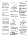
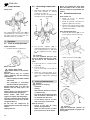
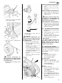
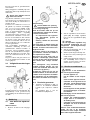
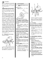
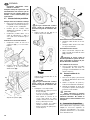
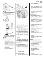
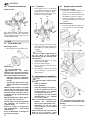
3.3 Safety devices
Safety valve
The spring-loaded safety valve (20) is
incorporated into the pressure switch.
The safety valve opens if the max. per-
missible pressure is exceeded.
4.1 Prior to initial operation
Wheel installation
1. Install the wheels as illustrated.
Mains connection
B
Danger! High voltage
Operate device in dry environ-
ment only.
Operate device only on a power
source complying with the following
requirements:
− outlets properly installed, earthed
and tested;
− fuse protection in accordance
with the technical specifications.
Position power cable so it does not
interfere with the work and is not
damaged.
Always check to see that the device is
switched OFF before plugging in.
Protect power cable from heat,
aggressive liquids and sharp edges.
Use only extension cables with suffi-
cient lead cross section (see "Techni-
cal Specifications").
Do not stop the compressor by
unplugging, but switch OFF using the
switch.
Unplug after use.
4.2 Generating compressed
air
1. Start device (23) and wait until the
max. tank pressure is reached
(compressor shuts off).
The tank pressure is indicated by
the tank pressure gauge
(24).
2. Set pressure regulator (22) to
required working pressure. The cur-
rent working pressure is indicated
by the regulated pressure gauge
(21).
A
Caution!
The regulated pressure may
not be set higher than the max. work-
ing pressure of the connected air
tools!
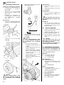
3. Connect air hose to compressed air
outlet (25).
4. Connect air tool.
You are now ready to work with the
air tool.
5. Switch the compressor OFF, if you
do not continue working immediately
afterwards. Unplug after switching
OFF.
A
Danger!
Prior to all servicing:
− Switch Off.
− Unplug.
− Wait until the device has come to
a complete stop.
− Ensure the device and all air tools
and accessories connected to it
are relieved from pressure.
− Let the device and all air tools
and accessories used cool off.
After all servicing:
− Check to see that all safety
devices are operational.
− Make sure that no tools or other
parts remain on or in the device.
Repair and maintenance work other
than described in this section must
only be carried out by qualified spe
-
cialists.
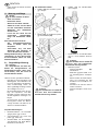
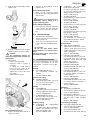
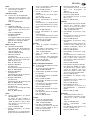
5.1 Periodic maintenance
Prior to each use
• Check air hoses for damage,
replace if necessary.
• Check all screwed connections for
tightness, tighten if necessary.
• Check power supply cable for dam-
age, if necessary have replaced by
a qualified electrician.
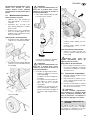
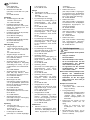
Every 50 operating hours
• Check air filter element (26) of com-
pressor pump, clean if necessary.
• Check oil level (27) of compressor
pump, top up if necessary (28).
• Drain condensate from pressure
vessel (30).
A
Caution!
The condensate contains oil
and must be disposed at a proper col-
lecting point.
4. Operation
20
5. Care and maintenance
23
24
21
22
25
26
27
29
28
30

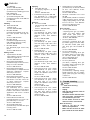
13
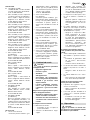
ENGLISH
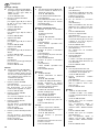
• Clean air filter element (31) of filter/
regulator unit.
• Drain the condensate from the filter/
regulator unit into a container (32).
A
Caution!
The condensate contains oil
and must be disposed at a proper col-
lecting point.
• Check V-belt:
− Remove belt guard (33).
− Retension V-belt or replace, if
necessary.
− To adjust the V-belt tension,
loosen the four screws at the
motor base and shift the motor.
− Tighten the screws at the motor
base again.
− Replace the belt guard.
Every 250 operating hours
• Replace air intake filter element of
compressor pump.
• Replace air filter element of filter/
regulator unit.
Every 500 operating hours
• Drain oil from compressor pump
through the drain plug
(29) and fill
with fresh oil.
A
Dispose of the waste oil envi-
ronmentally safe by taking it to a
proper collecting point!
Every 1000 operating hours
• Have unit serviced by an authorized
service station. This will extent the
compressor's service life considera
-
bly.
5.2 Device storage
1. Switch unit OFF and unplug.
2. Release pressure from tank and all
connected air tools.
3. Store device in such way that it can-
not be started by unauthorized per-
sons.
A
Caution!
Do not store device unpro-
tected outdoors or in damp environ-
ment.
Do not lay device on its side for trans-
portation or storing.
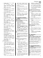
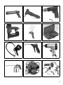
For special applications the following
accessories are available at your spe-
cialist dealer – see back cover for illus-
trations:
Sealing
A Air Caulking Gun KP 910
for commercially available car-
tridges.
Stock-no. 090 101 0030
Sheet metal cutting
B Air Nibbler BN 540
extra small cutting radius; cuts steel
sheet up to 1.0 mm thickness.
Stock-no. 090 100 6784
Drilling
C Air Drill BM 310
especially handy tool for low-fatigue
working; right-hand rotation only.
Stock-no. 090 100 6725
• Air Drill BM 500 (not shown)
with 3/8" keyless chuck, fully revers-
ible with quick reverse feature.
Stock-no. 090 105 4533
Stapling / nailing
D Combination Air Stapler/Nailer
Kombi 40/50
for staples (type 90) from 20 mm to
40
mm and finishing nails (type
SKN) from 20
mm to 50.
Stock-no. 090 105 4720
• Combination Air Stapler/Nailer
Kombi 32 (not illustrated)
for staples (type 90) from 15 mm to
32 mm and finishing nails (type
SKN) from 16 mm to 32 mm.
Stock-no. 090 105 4711
• Air Stapler KG 80/16
(not illustrated) for staples (type 80)
from 6 mm to 16 mm.
Stock-no. 090 105 4681
• Air Stapler KG 90/25
(not illustrated) for staples (type 90)
from 15 mm to 25 mm.
Stock-no. 090 105 4690
• Air Stapler KG 90/40
(not illustrated) for staples (type 90)
from 20 mm to 40 mm.
Stock-no. 090 105 4703
• Air Finish Nailer SKN 50
(not illustrated) for finishing nails
(type SKN) from 20
mm to 50 mm.
Stock-no. 090 105 4738
Spray painting
E Spray Gun FB 2200 HVLP
high-volume low-pressure feature
reduces paint mist bounce-back
and provides thicker coating at less
paint consumption.
Stock-no. 090 105 4460
• Paint Spray Gun FB 2200
(not illustrated) with 0.5 l flow cup;
professional spray gun; steplessly
adjustable round, horizontal and
vertical spray pattern.
Stock-no. 090 105 4452
• Paint Spray Gun SB 200
(not illustrated) with 1.0 l siphon cup.
Stock-no. 090 100 3882
• Paint Spray Gun FB 150
(not illustrated) with 0.5 l flow cup;
for spraying primers and paints of
varying viskosity.
Stock-no. 090 100 3874
• Paint Spray Gun FB 90
(not illustrated) with 0.75 l flow cup;
for spraying primers and paints of
varying viskosity.
Stock-no. 090 105 6064
Chiselling
F Air Hammer Set MHS 450
for construction and auto body work
Stock-no. 090 100 9210
• Air Hammer Set MHS 315
(not illustrated) to take off plaster
and tiles and for light chiselling
work.
Stock-no. 090 100 6911
Tyre inflating / checking
G Tyre Inflator Gauge RF 480
professional version (calibrated).
Stock-no. 090 105 4630
• Tyre Inflator Gauge RF 363
(not illustrated) same as RF 480, but
31
32
33
6. Available Accessories

14
ENGLISH
not calibrated.
Stock-no. 090 105 4622
• Tyre Inflator Gauge RF 200
(not illustrated) for inflating tyres and
balls (calibrated).
Stock-no. 090 105 6188
• Tyre Inflator Gauge RF 100
(not illustrated) same as RF 200, but
not calibrated.
Stock-no. 090 102 6724
Cleaning
H Blow Gun BP 200
all plastic body.
Stock-no. 090 105 4606
• Blow Gun BP 300
(not illustrated) all plastic body; ven-
turi nozzle provides extra high air
volume.
Stock-no. 090 105 4614
• Blow Gun BP 70
(not illustrated) light metal body
(with 100 mm extension nozzle).
Stock-no. 090 102 6726
• Blow Gun BP 60
(not illustrated) light metal body
(short).
Stock-no. 090 102 6718
Driving screws
I Impact Wrench SR 230
rugged impact wrench for DIY and
automotive applications.
Stock-no. 090 105 6170
• Impact Wrench SR 340 Set
(not illustrated) professional version;
many accessories included.
Stock-no. 090 105 6137
• Impact Wrench SR 140 Set
(not illustrated) for multiple DIY and
automotive applications; complete
with many accessories.
Stock-no. 090 100 8582
• Impact Wrench SR 120 Set
(not illustrated) requires only mini-
mal amount of air, thus can be run
on small compressors; complete
with many accessories.
Stock-no. 090 100 6750
• Ratchet Wrench RS 320
(not illustrated) due to narrow
design and rubber-covered ratchet
head it is well suited for automotive
applications and work in confined
areas.
Stock-no. 090 105 4541
• Ratchet Wrench RS 220 Set
(not illustrated) this set comes com-
plete with many accessories.
Stock-no. 090 100 6717
• Air Screwdriver DS 1610
(not illustrated) reversible with quick
reversing action.
Stock-no. 090 101 2440
Spraying
J Spray Gun SPP 161
for spraying degreaser, oil, liquid
wax, etc.
Stock-no. 090 105 4525
• Combination Spray Gun UBS 820
(not illustrated) for commercially
available 1.0 l screw-top cartridges.
Stock-no. 090 105 4479
Air hoses
K Hose Reel ST 200
swivels through 360°; with 30 m PU
air hose.
Stock-no. 090 105 4568
• Braided Air Hose
(not illustrated) c/w quick coupler
and male plug; length 5
m; outer
diameter 12 mm; inner diameter
6 mm.
Stock-no. 090 105 4908
• Braided Air Hose
(not illustrated) c/w quick coupler
and male plug; length 10 m; outer
diameter 12 mm; inner diameter
6
mm.
Stock-no. 090 105 4916
• Braided Air Hose
(not illustrated) c/w quick coupler
and male plug; length 10 m; outer
diameter 15 mm; inner diameter
9
mm.
Stock-no. 090 105 4924
• Bulk Braided Air Hose
(not illustrated) length 50 m; outer
diameter 15 mm; inner diameter
9 mm.
Stock-no. 090 105 4932
• Self-storing Coil Air Hose, Rilsan
(not illustrated) c/w quick coupler
and male plug; 2.5 m working
length; outer diameter 8
mm; inner
diameter 6 mm.
Stock-no. 090 105 4940
• Self-storing Coil Air Hose, Rilsan
(not illustrated) c/w quick coupler
and male plug; 7.5 m working
length; outer diameter 8
mm; inner
diameter 6
mm.
Stock-no. 090 105 4959
• Self-storing Coil Air Hose, Rilsan
(not illustrated) c/w quick coupler
and male plug; 10.0 m working
length; outer diameter 10
mm; inner
diameter 8 mm.
Stock-no. 090 105 4967
• Hand-crank Hose Reel SA 100
(not illustrated) c/w 20.0 m braided
air hose; outer diameter 15 mm;
inner diameter 9 mm.
Stock-no. 090 105 4975
• Automatic Retractable Hose Reel
SA 200
(not illustrated) suitable for wall and
ceiling mounting; retracts automati-
cally by simply pulling on hose; with
8
m PU air hose; outer diameter
13 mm; inner diameter 8 mm.
Stock-no. 090 105 4550
Accessory kits
L Accessory Kit LPZ 7-S
comprising: blow gun, tyre inflator
gauge, tyre valve adaptor, ball
valve needle, paint spray gun,
spray gun, self-storing coil air hose.
Stock-no. 090 100 3858
• Accessory Kit LPZ 7-P
(not illustr.) comprising: blow gun,
tyre inflator gauge, tyre valve adap
-
tor, ball valve needle, paint spray
gun, spray gun, 10 m braided air
hose.
Stock-no. 090 100 3890
• Accessory Kit LPZ 6-P
(not illustr.) comprising: blow gun,
tyre inflator gauge, tyre valve adap
-
tor, ball valve needle, paint spray
gun, 5 m braided air hose.
Stock-no. 090 104 4487
• Accessory Kit LPZ 4
(not illustr.) comprising blow gun,
tyre inflator gauge, paint spray gun,
self-storing coil air hose.
Stock-no. 090 101 3845
• Accessory Kit LPZ 2
(not illustrated) comprising change
handle with blow gun, tyre inflator
gauge, paint spray gun, self-storing
coil air hose.
Stock-no. 090 105 5971
A
Danger!
Prior to all servicing:
− Switch Off.
− Unplug.
− Wait until the device has come to
a complete stop.
− Ensure the device and all air tools
and accessories connected to it
are relieved from pressure.
− Let the device and all air tools
and accessories used cool off.
After all servicing:
− Check to see that all safety
devices are operational.
− Make sure that no tools or other
parts remain on or in the device.
7. Trouble shooting

15
ENGLISH
Compressor does not run:
• No mains voltage.
− Check cables, plug, outlet and
mains fuse.
• Mains voltage too low.
− Use only extension cables with
sufficient lead cross section (see
"Technical specifications"). Avoid
using extension cable when
device is cold.
• Compressor was stopped by
unplugging.
− Switch compressor OFF at the
On/Off switch, then ON again.
• Motor protection tripped, e.g. by
insufficient cooling (cooling fins cov
-
ered).
− Switch compressor OFF at the
On/Off switch; remove cause for
overheating; let cool off for
approx. 10 minutes; reset the
motor protection switch; switch
compressor ON again at the On/
Off switch.
Compressor runs but does not build
up sufficient pressure.
• Condensate drain of pressure ves-
sel leaky.
− Check gasket of drain cock(s);
replace if necessary.
− Tighten drain cock(s) fingertight.
• Drain cock on cup of filter/regulator
unit open.
− Tighten drain screw fingertight.
• Check valve leaky.
− Have check valve serviced by
qualified service centre.
Air tool is not supplied with sufficient
pressure.
• Pressure regulator not opened wide
enough.
− Open pressure regulator more.
• Hose connection between compres-
sor and air tool leaky.
− Check air hoses, replace defec-
tive parts if necessary.
A
Danger!
Repairs to power tools must be
carried out by qualified electricians
only!
Electric tools in need of repair can be
send to the service centre in your coun-
try. See spare parts list for address.
Please attach a description of the fault to
the power tool.
The machine's packaging can be 100 %
recycled.
Worn out devices and accessories con-
tain considerable amounts of valuable
raw and plastic materials, which can be
recycled.
These instructions are printed on chlo-
rine-free bleached paper.
8. Repairs
9. Environmental protection
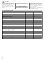
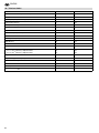
10. Technical specifications
Suction capacity l/min 330
Free air delivery (volume flow rate) l/min 190
Filling rate l/min 220
Working pressure (compression end pressure) bar 10
Pressure vessel volume l 50
No. of air outlets 2
Compressor pump model B 2800 B
No. of cylinders 2
Speed (compressor pump) min
-1
1499
Motor capacity kW 2.2
Supply voltage (50 Hz) V 230
Rated current A 10
Fuse protection min. A 16 (time-lag)
Degree of protection IP 44
Maximum overall length when using extension cables with:
– 3 x 1.5 mm
2
lead cross-section
– 3 x 2.5 mm
2
lead cross-section
m
m
30
50
Oil grade 10 W 40
Oil qantity for oil change l 0.21
Dimensions: length x width x height cm 88 x 49 x 77
Weight kg 54
Sound pressure level L
PA
at 4 m maximum dB (A) 73 ± 3
Sound power level L
WA
dB (A) 93 ± 3
Page is loading ...
Page is loading ...
Page is loading ...
Page is loading ...
Page is loading ...
Page is loading ...
Page is loading ...
Page is loading ...
Page is loading ...
Page is loading ...
Page is loading ...
Page is loading ...
Page is loading ...
Page is loading ...
Page is loading ...
Page is loading ...
Page is loading ...
Page is loading ...
Page is loading ...
Page is loading ...
Page is loading ...
Page is loading ...
Page is loading ...
Page is loading ...
Page is loading ...
Page is loading ...
Page is loading ...
Page is loading ...
Page is loading ...
Page is loading ...
Page is loading ...
Page is loading ...
Page is loading ...
Page is loading ...
Page is loading ...
Page is loading ...
Page is loading ...
Page is loading ...
Page is loading ...
Page is loading ...
Page is loading ...
Page is loading ...
Page is loading ...
Page is loading ...
Page is loading ...
Page is loading ...
Page is loading ...
Page is loading ...
-
 1
1
-
 2
2
-
 3
3
-
 4
4
-
 5
5
-
 6
6
-
 7
7
-
 8
8
-
 9
9
-
 10
10
-
 11
11
-
 12
12
-
 13
13
-
 14
14
-
 15
15
-
 16
16
-
 17
17
-
 18
18
-
 19
19
-
 20
20
-
 21
21
-
 22
22
-
 23
23
-
 24
24
-
 25
25
-
 26
26
-
 27
27
-
 28
28
-
 29
29
-
 30
30
-
 31
31
-
 32
32
-
 33
33
-
 34
34
-
 35
35
-
 36
36
-
 37
37
-
 38
38
-
 39
39
-
 40
40
-
 41
41
-
 42
42
-
 43
43
-
 44
44
-
 45
45
-
 46
46
-
 47
47
-
 48
48
-
 49
49
-
 50
50
-
 51
51
-
 52
52
-
 53
53
-
 54
54
-
 55
55
-
 56
56
-
 57
57
-
 58
58
-
 59
59
-
 60
60
-
 61
61
-
 62
62
-
 63
63


Metabo Mega 450 W Operating instructions
- Category
- Air compressors
- Type
- Operating instructions
Ask a question and I''ll find the answer in the document
Finding information in a document is now easier with AI
in other languages
- italiano: Metabo Mega 450 W Istruzioni per l'uso
- français: Metabo Mega 450 W Mode d'emploi
- español: Metabo Mega 450 W Instrucciones de operación
- Deutsch: Metabo Mega 450 W Bedienungsanleitung
- Nederlands: Metabo Mega 450 W Handleiding
- dansk: Metabo Mega 450 W Betjeningsvejledning
- svenska: Metabo Mega 450 W Bruksanvisningar
- suomi: Metabo Mega 450 W Käyttö ohjeet
Related papers
-
Metabo Mega 350 D Operating instructions
-
-
-
-
Metabo Mega 550-90 D Operating instructions
-
Metabo Power 280-20 W OF Operating instructions
-
-
-
-
Metabo Mega 350-100 D Operating instructions
Other documents
-
 Elektra Beckum Air Compressor Mega 350 D User manual
-
Michelin MCX200 Instruction Manual And Safety Instructions
-
Ferm ATM1037 User manual
-
 Avois AV-3000 Series User guide
-
Stanley DN 200-10-24 Owner's manual
-
sks X TRA DRY XL User manual
-
-
EINHELL BT-AC 200-24 OF Owner's manual
-
BLACK DECKER ASI300 T3 User manual
-
Paslode Proline 248 User And Maintenance Manual

