Craftsman 139.18452D User manual
- Category
- Garage Door Opener
- Type
- User manual
This manual is also suitable for

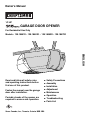
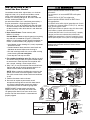
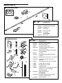
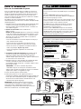
1/2 HP
GARAGE DOOR OPENER
For Residential Use Only
Models • 139.18451D • 139.18452D • 139.18453D • 139.18473D
®
Read and follow all safety rules
and operating instructions before
first use of this product.
Fasten the manual near the garage
door after installation.
Periodic checks of the opener are
required to ensure safe operation.
Owner’s Manual
ENGLISH
Sears Canada, Inc., Toronto, Ontario M5B 2B8
■ Safety Precautions
■ Assembly
■ Installation
■ Adjustment
■ Maintenance
■ Operation
■ Troubleshooting
■ Parts List

2
TABLE OF CONTENTS
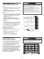
When you see these Safety Symbols and Signal Words
on the following pages, they will alert you to the
possibility of serious injury or death if you do not
comply with the warnings that accompany them. The
hazard may come from something mechanical or from
electric shock. Read the warnings carefully.
When you see this Signal Word on the following pages, it
will alert you to the possibility of damage to your garage
door and/or the garage door opener if you do not comply
with the cautionary statements that accompany it. Read
them carefully.
INTRODUCTION
Safety Symbol
and Signal Word Review
This garage door opener has been designed and tested to offer safe service provided it is installed, operated,
maintained and tested in strict accordance with the instructions and warnings contained in this manual.
Mechanical
Electrical
WARNING
CAUTION
WARNING
WARNING
WARNING
CAUTION
WARNING
WARNING
WARNING
CAUTION
WARNING
WARNING
Introduction 2-7
Safety symbol and signal word review........................2
Preparing your garage door ........................................3
Tools needed...............................................................3
Planning ..................................................................4-5
Carton inventory..........................................................6
Hardware inventory .....................................................7
Assembly 8-11
Assemble the rail and install the trolley ......................8
Fasten the rail to the motor unit and
install the idler pulley...................................................9
Install the chain/cable................................................10
Tighten the chain .......................................................11
Installation 11-26
Installation safety instructions....................................11
Determine the header bracket location .....................12
Install the header bracket..........................................13
Attach the rail to the header bracket.........................14
Position the opener ...................................................15
Hang the opener .......................................................16
Install the door control...............................................17
Install the light ...........................................................18
Attach the emergency release rope and handle .......18
Electrical requirements..............................................19
Install The Protector System
®
..............................20-22
Fasten the door bracket.......................................23-24
Connect the door arm to the trolley .....................25-26
Adjustment 27-29
Adjust the travel limits ...............................................27
Adjust the force .........................................................28
Test the safety reversal system.................................29
Test The Protector System
®
......................................29
Operation 30-34
Operation safety instructions.....................................30
Using your garage door opener ................................30
Using the wall-mounted Door Control .......................31
To open the door manually........................................31
Care of your garage door opener..............................32
Having a problem? ....................................................33
Diagnostic chart.........................................................34
Programming 35-36
To add or reprogram a hand-held remote control .....35
To erase all codes .....................................................35
3-Function Remotes..................................................35
To add, reprogram or change
a Keyless Entry PIN ..................................................36
Repair Parts 37-38
Rail assembly parts...................................................37
Installation parts ........................................................37
Motor unit assembly parts.........................................38
Accessories 39
Warranty 39
Repair Parts and Service 40

3
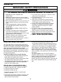
To prevent damage to garage door and opener:
• ALWAYS disable locks BEFORE installing and operating the
opener.
• ONLY operate garage door opener at 120V, 60 Hz to avoid
malfunction and damage.
To prevent possible SERIOUS INJURY or DEATH:
• ALWAYS call a trained door systems technician if garage
door binds, sticks, or is out of balance. An unbalanced
garage door may not reverse when required.
• NEVER try to loosen, move or adjust garage door, door
springs, cables, pulleys, brackets or their hardware, all of
which are under EXTREME tension.
• Disable ALL locks and remove ALL ropes connected to
garage door BEFORE installing and operating garage door
opener to avoid entanglement.
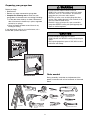
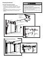
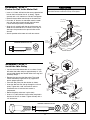
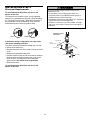
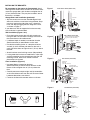
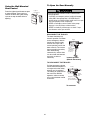
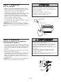
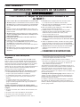
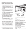
Preparing your garage door
Before you begin:
• Disable locks.
• Remove any ropes connected to garage door.
• Complete the following test to make sure your
garage door is balanced and is not sticking or binding:
1. Lift the door about halfway as shown. Release the
door. If balanced, it should stay in place, supported
entirely by its springs.
2. Raise and lower the door to see if there is any
binding or sticking.
If your door binds, sticks, or is out of balance, call a
trained door systems technician.
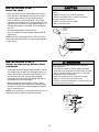
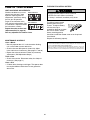
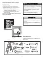
Tools needed
During assembly, installation and adjustment of the
opener, instructions will call for hand tools as illustrated
below.
WARNING
CAUTION
WARNING
WARNING
WARNING
CAUTION
WARNING
WARNING
Pliers
Wire Cutters
Claw Hammer
Hack Saw
Screwdriver
Adjustable End Wrench
Sockets and Wrench
1/2", 5/8", 7/16", 9/16"
and 1/4"
Drill
Tape Measure
2
1
Stepladder
Pencil
Drill Bits
3/16", 5/16"
and 5/32"
Carpenter's
Level (optional)
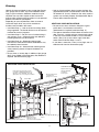
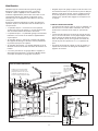
Sectional Door
One-Piece Door

4
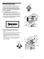
Safety Reversing Sensor
Header Wall
Access Door
— — — — — — — —
Safety Reversing
Sensor
Gap between floor
and bottom of door
must not exceed 1/4" (6 mm).
Extension Spring
Horizontal and vertical reinforcement
is needed for lightweight garage doors
(fiberglass, steel, aluminum, door with
glass panels, etc.). See page 23 for details.
Support bracket &
fastening hardware
is required.
See page 16.
FINISHED CEILING
Motor unit
Wall-
mounted
Door
Control
OR
Torsion Spring
Slack in chain tension
is normal when
garage door is closed.
Vertical
Centerline
of Garage
Door
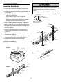
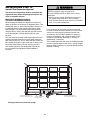
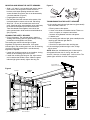
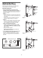
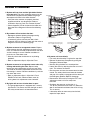
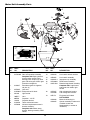
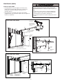
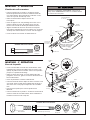
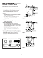
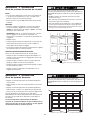
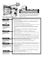
SECTIONAL DOOR INSTALLATION
Planning
Identify the type and height of your garage door. Survey
your garage area to see if any of the conditions below
apply to your installation. Additional materials may be
required. You may find it helpful to refer back to this
page and the accompanying illustrations as you proceed
with the installation of your opener.
Depending on your requirements, there are several
installation steps which may call for materials or
hardware not included in the carton.
• Installation Step 1 – Look at the wall or ceiling above
the garage door. The header bracket must be securely
fastened to structural supports.
• Installation Step 5 – Do you have a finished ceiling in
your garage? If so, a support bracket and additional
fastening hardware may be required.
• Installation Step 10 – Depending upon garage
construction, extension brackets or wood blocks may
be needed to install sensors.
• Installation Step 10 – Alternate floor mounting of the
safety reversing sensor will require hardware not
provided.
• Do you have an access door in addition to the garage
door? If not, Model 18752 Emergency Key Release is
required. See Accessories page.
Trolley
Header
Wall
Garage
Door
Header
Bracket
Straight
Door
Arm
Emergency
Release
Rope & Handle
Door
Bracket
Curved
Door
Arm
Garage
Door
Spring
Chain
Trolley
Stop Bolt
CLOSED POSITION
• Look at the garage door where it meets the floor. Any
gap between the floor and the bottom of the door must
not exceed 1/4" (6 mm). Otherwise, the safety reversal
system may not work properly. See Adjustment Step 3.
Floor or door should be repaired.
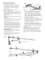
SECTIONAL DOOR INSTALLATIONS
• Do you have a steel, aluminum, fiberglass or glass
panel door? If so, horizontal and vertical
reinforcement is required (Installation Step 11).
• The opener should be installed above the center of the
door. If there is a torsion spring or center bearing plate
in the way of the header bracket, it may be installed
within 4 feet (1.22 m) to the left or right of the door
center. See Installation Steps 1 and 11.
• If your door is more than 7 feet (2.13 m) high, see rail
extension kits listed on Accessories page.

5
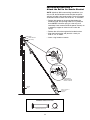
Access
Door
Safety
Reversing Sensor
Safety
Reversing
Sensor
Gap between floor
and bottom of door
must not exceed 1/4" (6 mm).
Door
Bracket
Straight
Door
Arm
Garage
Door
CLOSED POSITION
Header
Bracket
Curved
Door Arm
Chain
Emergency
Release
Rope &
Handle
Cable
Rail
Trolley Stop Bolt
Header
Wall
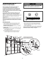
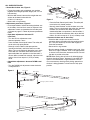
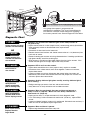
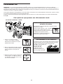
Planning (Continued)
ONE-PIECE DOOR INSTALLATIONS
• Generally, a one-piece door does not require
reinforcement. If your door is lightweight, refer to the
information relating to sectional doors in Installation
Step 11.
• Depending on your door’s construction, you may need
additional mounting hardware for the door bracket
(Step 11).
Safety Reversing Sensor
Access
Door
FINISHED CEILING
Support bracket
& fastening
hardware is required.
See page 16.
Safety Reversing
Sensor
Header Wall
Gap between floor
and bottom of door must not exceed 1/4" (6 mm).
Wall-mounted
Door Control
Rail
Motor Unit
Slack in chain tension
is normal when garage
door is closed.
ONE-PIECE DOOR WITHOUT TRACK
Header
Bracket
Trolley
Straight
Door
Arm
Emergency
Release
Rope & Handle
Door Bracket
Curved
Door
Arm
Header
Wall
Cable
Rail
Garage Door
Trolley Stop Bolt
CLOSED POSITION
Without a properly working safety reversal system, persons
(particularly small children) could be SERIOUSLY INJURED
or KILLED by a closing garage door.
• The gap between the bottom of the garage door and the
floor MUST NOT exceed 1/4" (6 mm). Otherwise, the safety
reversal system may not work properly.
• The floor or the garage door MUST be repaired to eliminate
the gap.
WARNING
CAUTION
WARNING
WARNING
ONE-PIECE DOOR WITH TRACK

6
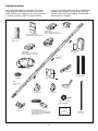
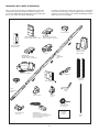
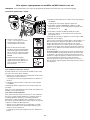
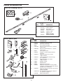
Your garage door opener is packaged in one carton
which contains the motor unit and all parts illustrated
below. Accessories will depend on the model purchased.
If anything is missing, carefully check the packing
material. Parts may be stuck in the foam. Hardware for
assembly and installation is shown on the next page.
Save the carton and packing material until installation
and adjustment is complete.
Carton Inventory
Straight Door
Arm Section
Curved Door
Arm Section
Safety Labels
and
Literature
2-Conductor Bell Wire
White & White/Red
Idler Pulley
Chain and Cable
Hanging Brackets
The Protector System
®
(2) Safety Reversing Sensors
(1 Sending Eye and 1 Receiving Eye)
with 2-Conductor White & White/Black
Bell Wire attached
Door Bracket
Trolley
Safety Sensor
Bracket (2)
Rail
Center/Back
Sections
"U" Bracket
Rail
Front (header)
Section
Header Bracket
Chain Spreader
Motor Unit with a Light Lens
SECURITY✚
®
3-Function Remote Control
Standard Control Console
Door Control Button
SECURITY✚
®
Single-Function Remote Control
Garage Door Monitor System
Models 18452D, 18453D, 18473D
Model 18451D
Models 18451D (1), 18452D (2)
Models 18453D (2), 18473D (2)
Model 18473D

7
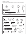
Master
Link (2)
Idler Bolt (1)
Nut
3/8" (1)
Trolley Threaded Shaft (1)
Bolt 1/4"-20x1-3/4" (2)
Lock Washer
3/8" (1)
Lock Nut
1/4"-20 (2)
Spacer (2)
Wing Nut
1/4"-20 (2)
Carriage Bolt
1/4"-20x1/2" (2)
Handle
Nut 5/16"-18 (8)
Ring
Fastener (3)
Insulated
Staples (30)
Drywall Anchors (2)
Clevis Pin
5/16"x1" (1)
Rope
Carriage Bolt
5/16"-18x2-1/2" (2)
Lock Washer 5/16" (7)
Lag Screw
5/16"-9x1-5/8" (2)
Hex Bolt
5/16"-18x7/8" (4)
Clevis Pin
5/16"x1-1/4" (1)
Lag Screw
5/16"-18x1-7/8" (2)
Screw
6ABx1-1/4" (2)
Screw 6-32x1" (2)
Clevis Pin
5/16"x1-1/2" (1)
Screw 6ABx1-1/2"
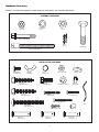
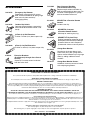
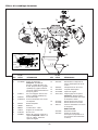
Hardware Inventory
Separate all hardware and group as shown below for the assembly and installation procedures.
ASSEMBLY HARDWARE
INSTALLATION HARDWARE

FRONT RAIL
(TOP)
KEEP LARGER
HOLE ON TOP
8
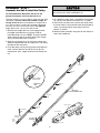
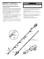
ASSEMBLY STEP 1
Assemble the Rail & Install the Trolley
To avoid installation difficulties, do not run the
garage door opener until instructed to do so.
To prevent INJURY from pinching, keep hands and fingers
away from the joints while assembling the rail.
WARNING
CAUTION
WARNING
WARNING
Front Rail
(TO DOOR)
Window
Cut-Out
Screwdriver
Idler
Pulley
Hole
Tabs
Back Rails
(TO MOTOR UNIT)
Trolley
Tapered
End
Tapered
End
Inner Trolley
Wear Pads
Outer Trolley
Tapered
End
Tapered
End
The front rail has a cut out “window” at the door end (see
illustration). The hole above this window is larger on
the top of the rail than on the bottom. A smaller hole 3-
1/2" (8.9 cm) away is close to the rail edge. Rotate the
back rail so it has a similar hole close to the opposite
edge, about 4-3/4" (12 cm) from the far end.
1. Remove the straight door arm and hanging bracket
packaged inside the front rail and set aside for
Installation Step 5 and 12. NOTE: To prevent INJURY
while unpacking the rail carefully remove the straight
door arm stored within the rail section.
2. Align the rail sections on a flat surface as shown and
slide the tapered ends into the larger ones. Tabs along
the side will lock into place.
3. Place the motor unit on packing material to protect the
cover, and rest the back end of the rail on top. For
convenience, put a support under the front end of the
rail.
4. As a temporary stop, insert a screwdriver into the hole
10" (25 cm) from the front end of the rail, as shown.
5. Check to be sure there are 4 plastic wear pads inside
the inner trolley. If they became loose during shipping,
check all packing material. Snap them back into
position as shown.
6. Slide the trolley assembly along the rail from the back
end to the screwdriver.

9
To avoid SERIOUS damage to garage door opener, use ONLY
those bolts/fasteners mounted in the top of the opener.
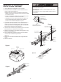
ASSEMBLY STEP 2
Fasten the Rail to the Motor Unit
• Insert a 1/4"-20x1-3/4 bolt into the cover protection bolt
hole on the back end of the rail as shown. Tighten
securely with a 1/4"-20 lock nut. Do NOT overtighten.
• Remove the two bolts from the top of the motor unit.
• Place the “U” bracket, flat side down onto the motor
unit and align the bracket hole with the bolt holes.
Fasten with the previously removed bolts.
• Align the rail assembly with the top of the motor unit.
Slide the rail end onto the “U” bracket, all the way to
the stops that protrude on the top and sides of the
bracket.
• Attach spreader to the motor unit with two screws.
ASSEMBLY STEP 3
Install the Idler Pulley
• Lay the chain/cable beside the rail, as shown. Grasp
the end of the cable and pass approximately 12" (30
cm) of cable through the window. Allow it to hang until
Assembly Step 5.
• Remove the tape from the idler pulley. The inside
center should be pre-greased. If dry, regrease to
ensure proper operation.
• Place the idler pulley into the window as shown.
• Insert the idler bolt from the top through the rail and
pulley. Tighten with a 3/8" lock washer and nut
underneath the rail until the lock washer is
compressed.
• Rotate the pulley to be sure it spins freely.
• Insert a 1/4"-20x1-3/4 bolt into the trolley stop hole in
the front of the rail as shown. Tighten securely with a
1/4"-20 lock nut.
WARNING
CAUTION
WARNING
WARNING
Bolt
Motor Unit
Sprocket
"U" Bracket
Hex Screws
8-32x7/16"
Chain
Spreader
Lock Nut
Cover
Protection
Bolt Hole
Bolt
SLIDE RAIL TO STOPS
ON TOP AND SIDES
OF BRACKET
Lock Nut
1/4"-20
Bolt 1/4"-20x1-3/4"
HARDWARE SHOWN ACTUAL SIZE
Nut 3/8"
Lock Washer 3/8"
Idler Bolt
Lock Nut 1/4"-20
Bolt 1/4"-20x1-3/4
HARDWARE SHOWN ACTUAL SIZE
Lock
Washer
3/8"
Nut 3/8"
Cable Link
Idler
Bolt
Chain and
Cable
Pulley
Rail
Bolt
Nut
Washer
Trolley
Idler
Pulley
Idler
Pulley
Grease
Inside Pulley
Screwdriver
Trolley
Stop Hole
Bolt
Lock
Nut

Round
Hole
Trolley
Threaded
Shaft
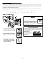
ASSEMBLY STEP 4
Install the Chain/Cable
1. Pull the cable around the idler pulley and toward the
trolley.
2. Connect the cable to the retaining slot on the trolley, as
shown (Figure 1):
• From below, push pins of master link bar up through
cable link and trolley slot.
• Push master link cap over pins and past pin
notches.
• Slide clip-on spring over cap and onto pin notches
until both pins are securely locked in place.
3. With the trolley against the screwdriver, dispense the
remainder of the cable/chain along the rail toward the
motor unit into the slot on the chain spreader, around
the sprocket onto the chain spreader and continuing to
the trolley assembly. The sprocket teeth must engage
the chain (Figure 2).
4. Check to make sure the chain is not twisted, then
connect it to the threaded shaft with the remaining
master link.
5. Thread the inner nut and lock washer onto the trolley
threaded shaft (Figure 3).
6. Insert the trolley threaded shaft through the hole in the
trolley. Be sure the chain is not twisted (Figure 4).
7. Loosely thread the outer nut onto the trolley
threaded shaft.
8. Remove the screwdriver.
10
To avoid possible SERIOUS INJURY to fingers from moving
garage door opener:
• ALWAYS keep hand clear of sprocket while operating
opener.
• Securely attach chain spreader BEFORE operating.
Leave Chain and Cable
Inside Dispensing
Carton to Prevent Kinking.
Dispensing Carton
Keep Chain and Cable
Taut When Dispensing
WARNING
CAUTION
WARNING
WARNING
"U" Bracket
Motor Unit
Sprocket
Chain
Spreader
Bolt
K
G
K
G
Figure 1
Figure 2
Trolley
Threaded
Shaft
Inner Nut
5/16"
Lock
Washer
5/16"
Figure 3
Figure 4
Idler
Pulley
Round
Hole
Master Link
Clip-On Spring
Master
Link Cap
Trolley
Threaded
Shaft
Master
Link Bar
Cable
Link
Cable
Pin
Notch
Master Link
Clip-On Spring
Master
Link Cap
Slotted
Hole
Master
Link Bar

11
INSTALLATION
ASSEMBLY STEP 5
Tighten the Chain
• Spin the inner nut and lock washer down the trolley
threaded shaft, away from the trolley.
• To tighten the chain, turn outer nut in the direction
shown (Figure 1).
• When the chain is approximately 1/4" (6 mm) above
the base of the rail at its midpoint, re-tighten the inner
nut to secure the adjustment.
Sprocket noise can result if chain is too loose.
When installation is complete, you may notice some
chain droop with the door closed. This is normal. If the
chain returns to the position shown in Figure 2 when the
door is open, do not re-adjust the chain.
NOTE: During future maintenance, ALWAYS pull the
emergency release handle to disconnect trolley before
adjusting chain.
NOTE: You may notice loosening of chain after
Adjustment Step 3 (Test the Safety Reversal System).
Check for proper tension and readjust chain if necessary.
Then repeat Adjustment Step 3.
You have now finished assembling your garage door
opener. Please read the following warnings before
proceeding to the installation section.
Outer
Nut
Lock
Washer
Trolley
Threaded
Shaft
Inner Nut
To Tighten
Inner Nut
To Tighten Outer Nut
Base of Rail
Mid length of Rail
Chain
1/4" (6 mm)
Figure 1
Figure 2
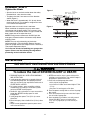
IMPORTANT INSTALLATION INSTRUCTIONS
To reduce the risk of SEVERE INJURY or DEATH:
WARNING
WARNING
WARNING
1. READ AND FOLLOW ALL INSTALLATION WARNINGS
AND INSTRUCTIONS.
2. Install garage door opener only on properly balanced
and lubricated garage door. An improperly balanced
door may not reverse when required and could result in
SEVERE INJURY or DEATH.
3. ALL repairs to cables, spring assemblies and other
hardware MUST be made by a trained door systems
technician BEFORE installing opener.
4. Disable ALL locks and remove ALL ropes connected to
garage door BEFORE installing opener to avoid
entanglement.
5. Install garage door opener 7 feet (2.13 m) or more
above floor.
6. Mount emergency release handle 6 feet (1.83 m) above
floor.
7. NEVER connect garage door opener to power source
until instructed to do so.
8. NEVER wear watches, rings or loose clothing while
installing or servicing opener. They could be caught in
garage door or opener mechanisms.
9. Install wall-mounted garage door control:
• within sight of the garage door.
• out of reach of children at minimum height of 5 feet
(1.5 m).
• away from ALL moving parts of the door.
10. Place entrapment warning label on wall next to garage
door control.
11. Place manual release/safety reverse test label in plain
view on inside of garage door.
12. Upon completion of installation, test safety reversal
system. Door MUST reverse on contact with a
1-1/2" (3.8 cm) high object (or a 2x4 laid flat) on
the floor.

12
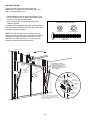
INSTALLATION STEP 1
Determine the Header Bracket
Location
Installation procedures vary according to garage door
types. Follow the instructions which apply to your door.
1. Close the door and mark the inside vertical centerline
of the garage door.
2. Extend the line onto the header wall above the door.
You can fasten the header bracket within 4 feet
(1.22 m) of the left or right of the door center only
if a torsion spring or center bearing plate is in the
way; or you can attach it to the ceiling (see
page 13) when clearance is minimal. (It may be
mounted on the wall upside down if necessary, to
gain approximately 1/2" (1 cm).
If you need to install the header bracket on a 2x4
(on wall or ceiling), use lag screws (not provided)
to securely fasten the 2x4 to structural supports as
shown here and on page 13.
3. Open your door to the highest point of travel as shown.
Draw an intersecting horizontal line on the header wall
above the high point:
• 2" (5 cm) above the high point for sectional door
and one-piece door with track.
• 8" (20 cm) above the high point for one-piece door
without track.
This height will provide travel clearance for the top
edge of the door.
NOTE: If the total number of inches exceeds the
height available in your garage, use the maximum
height possible, or refer to page 13 for ceiling
installation.
To prevent possible SERIOUS INJURY or DEATH:
• Header bracket MUST be RIGIDLY fastened to structural
support on header wall or ceiling, otherwise garage door
might not reverse when required. DO NOT install header
bracket over drywall.
• Concrete anchors MUST be used if mounting header
bracket or 2x4 into masonry.
• NEVER try to loosen, move or adjust garage door, springs,
cables, pulleys, brackets, or their hardware, all of which are
under EXTREME tension.
• ALWAYS call a trained door systems technician if garage
door binds, sticks, or is out of balance. An unbalanced
garage door might not reverse when required.
Header Wall
Sectional door with curved track
Highest Point
of Travel
Door
2" (5 cm)
One-piece door with horizontal track
Door
Track
Header Wall
Highest Point
of Travel
2" (5 cm)
Track
Header Wall
Vertical Centerline
of Garage Door
Level
(optional)
2x4
2x4
Structural
Supports
OPTIONAL
CEILING
MOUNT
FOR
HEADER
BRACKET
Unfinished
Ceiling
WARNING
CAUTION
WARNING
WARNING
Door
Jamb
Hardware
One-piece door without track:
jamb hardware
8" (20 cm)
Highest
Point
of Travel
Door
Pivot
8" (20 cm)
One-piece door without track:
pivot hardware
Highest
Point
of Travel
Header Wall
Header Wall

13
Lag Screws
5/16"-9x1-5/8"
– Finished Ceiling –
Door
Spring
Header Wall
UP
Ceiling Mounting Holes
6" (15 cm) Maximum
Header
Bracket
Vertical
Centerline
of Garage Door
Garage Door
Vertical Centerline
of Garage Door
INSTALLATION STEP 2
Install the Header Bracket
You can attach the header bracket either to the wall
above the garage door, or to the ceiling. Follow the
instructions which will work best for your particular
requirements. Do not install the header bracket over
drywall. If installing into masonry, use concrete
anchors (not provided).
WALL HEADER BRACKET INSTALLATION
• Center the bracket on the vertical centerline with the
bottom edge of the bracket on the horizontal line as
shown (with the arrow pointing toward the ceiling).
• Mark the vertical set of bracket holes. Drill 3/16" pilot
holes and fasten the bracket securely to a structural
support with the hardware provided.
Lag Screw
5/16"-9x1-5/8"
HARDWARE SHOWN ACTUAL SIZE
CEILING HEADER BRACKET INSTALLATION
• Extend the vertical centerline onto the ceiling as
shown.
• Center the bracket on the vertical mark, no more than
6" (15 cm) from the wall. Make sure the arrow is
pointing away from the wall. The bracket can be
mounted flush against the ceiling when clearance
is minimal.
• Mark the side holes. Drill 3/16" pilot holes and fasten
bracket securely to a structural support with the
hardware provided.
UP
Wall Mount
Optional
Mounting Holes
Lag Screws
5/16"-9x1-5/8"
Highest Point of
Garage Door Travel
Vertical
Centerline
of Garage Door
Header
Wall
Garage
Door
Door Spring
2x4
Structural
Support
Vertical
Centerline
of Garage Door
Header
Bracket
Horizontal
Line

14
INSTALLATION STEP 3
Attach the Rail to the Header Bracket
NOTE: (Optional) With some existing installations, you
may re-use the old header bracket with the two plastic
spacers included in the hardware bag. Place the spacers
inside the bracket on each side of the rail, as illustrated.
• Position the opener on the garage floor below the
header bracket. Use packing material as a protective
base. NOTE: If the door spring is in the way you’ll
need help. Have someone hold the opener securely on
a temporary support to allow the rail to clear the
spring.
• Position the rail bracket against the header bracket.
• Align the bracket holes and join with a clevis pin
5/16"x1-1/2" as shown.
• Insert a ring fastener to secure.
Opener Carton or
Temporary
Support
Garage
Door
OPTION WITH
SOME EXISTING
INSTALLATIONS
Header Bracket
Idler Pulley
Header Wall
Header
Bracket
Mounting
Hole
Existing
Header Bracket
Spacer
Mounting
Hole
Existing
Clevis Pin
Clevis Pin 5/16"x1-1/2"
Ring Fastener
HARDWARE SHOWN ACTUAL SIZE

15
ONE-PIECE DOOR WITHOUT TRACK
A 2x4 on its side is convenient for setting an ideal door-
to-rail distance.
• Remove foam packaging.
• Raise the opener onto a stepladder. You will need help
at this point if the ladder is not tall enough.
• Open the door all the way and place a 2x4 on its side
on the top section of the door beneath the rail.
• The top of the door should be level with the top of the
motor unit. Do not position the opener more than 4"
(10 cm) above this point.
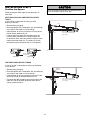
INSTALLATION STEP 4
Position the Opener
Follow instructions which apply to your door type as
illustrated.
SECTIONAL DOOR OR ONE-PIECE DOOR WITH
TRACK
A 2x4 laid flat is convenient for setting an ideal
door-to-rail distance.
• Remove foam packaging.
• Raise the opener onto a stepladder. You will need help
at this point if the ladder is not tall enough.
• Open the door all the way and place a 2x4 laid flat on
the top section beneath the rail.
• If the top section or panel hits the trolley when you
raise the door, pull down on the trolley release arm
to disconnect inner and outer sections. Slide the outer
trolley toward the motor unit. The trolley can remain
disconnected until Installation Step 12 is completed.
To prevent damage to garage door, rest garage door opener
rail on 2x4 placed on top section of door.
WARNING
CAUTION
WARNING
WARNING
Header
Bracket
Top of Door
2x4 is used to determine
the correct mounting height
from ceiling.
Rail
2x4 is used to determine
the correct mounting height
from ceiling.
Door
ENGAGED
RELEASED
Trolley
Release Arm

16
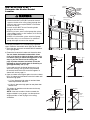
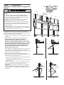
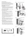
INSTALLATION STEP 5
Hang the Opener
Three representative installations are shown. Yours may
be different. Hanging brackets should be angled (Figure
1) to provide rigid support. On finished ceilings (Figure 2
and Figure 3), attach a sturdy metal bracket to structural
supports before installing the opener. This bracket and
fastening hardware are not provided.
1. Measure the distance from each side of the motor unit
to the structural support.
2. Cut both pieces of the hanging bracket to required
lengths.
3. Drill 3/16" pilot holes in the structural supports.
4. Attach one end of each bracket to a support with
5/16"-18x1-7/8" lag screws.
5. Fasten the opener to the hanging brackets with 5/16"-
18x7/8" hex bolts, lock washers and nuts.
6. Check to make sure the rail is centered over the door
(or in line with the header bracket if the bracket is not
centered above the door).
7. Remove the 2x4. Operate the door manually. If the
door hits the rail, raise the header bracket.
NOTE: DO NOT connect power to opener at
this time.
To avoid possible SERIOUS INJURY from a falling garage
door opener, fasten it SECURELY to structural supports of
the garage. Concrete anchors MUST be used if installing any
brackets into masonry.
Lag Screw 5/16"-18x1-7/8"
Hex Bolt
5/16"-18x7/8"
Nut 5/16"-18
Lock Washer 5/16"
HARDWARE SHOWN ACTUAL SIZE
Measure
Distance
Lag Screws
5/16"-18x1-7/8"
Structural
Supports
Bracket
(Not Provided)
Lag Screws
5/16"-18x1-7/8"
Hidden
Support
Bolt 5/16"-18x7/8"
Lock Washer 5/16"
Nut 5/16"-18
(Not Provided)
Bolt 5/16"-18x7/8"
Lock Washer 5/16"
Nut 5/16"-18
FINISHED CEILING
Bolt 5/16"-18x7/8"
Lock Washer 5/16"
Nut 5/16"-18
Bolt 5/16"-18x7/8"
Lock Washer 5/16"
Nut 5/16"-18
Lag Screws
5/16"-18x1-7/8"
FINISHED CEILING
(Not Provided)
Bolt 5/16"-18x7/8"
Lock Washer 5/16"
Nut 5/16"-18
Figure 1
Figure 2
WARNING
CAUTION
WARNING
WARNING
Figure 3

17
To prevent possible SERIOUS INJURY or DEATH from
electrocution:
• Be sure power is not connected BEFORE installing door
control.
• Connect ONLY to 24 VOLT low voltage wires.
To prevent possible SERIOUS INJURY or DEATH from a
closing garage door:
• Install door control within sight of garage door, out of reach
of children at a minimum height of 5 feet (1.5 m), and away
from all moving parts of door.
• NEVER permit children to operate or play with door control
push buttons or remote control transmitters.
• Activate door ONLY when it can be seen clearly, is properly
adjusted, and there are no obstructions to door travel.
• ALWAYS keep garage door in sight until completely closed.
NEVER permit anyone to cross path of closing garage door.
WARNING
CAUTION
WARNING
WARNING
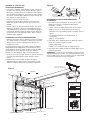
INSTALLATION STEP 6
Install the Door Control
Locate door control within sight of door, at a minimum
height of 5 feet (1.5 m) where small children cannot
reach, away from moving parts of door and door
hardware. If installing into drywall, drill 5/32" holes and
use the anchors provided. For
pre-wired installations (as in new home construction), it
may be mounted to a single gang box (Figure 2).
1. Strip 7/16" (11 mm) of insulation from one end of bell
wire and connect to the two screw terminals on back
of door control by color: white wire to 2 and white/red
wire to the 1.
2. Door Control Button: Fasten securely with
6ABx1-1/2" screws.
Console Model: Remove cover by gently prying along
one side with a screwdriver (Figure 1). Fasten with
6ABx1-1/4" self-tapping screws (drywall installation) or
6-32x1" machine screws (into gang box) as follows:
• Install bottom screw, allowing 1/8" (3 mm) to protrude
above wall surface.
• Position bottom of door control on screw head and
slide down to secure. Adjust screw for snug fit.
• Drill and install top screw with care to avoid cracking
plastic housing. Do not overtighten.
• Insert top tabs and snap on cover.
3. (For standard installation only) Run bell wire up wall
and across ceiling to motor unit. Use insulated staples
to secure wire in several places. Do not pierce wire
with a staple, creating a short or open circuit.
4. Strip 7/16" (11 mm) of insulation from end of bell wire.
Connect bell wire to the quick-connect terminals as
follows: white to white and white/red to red.
NOTE: When connecting multiple door controls to the
opener, twist same color wires together. Insert wires
into quick-connect holes: white to white and red/white
to red.
5. Position the antenna wire as shown.
6. Use tacks or staples to permanently attach
entrapment warning label to wall near door control,
and manual release/safety reverse test label in
a prominent location on inside of garage door.
NOTE: DO NOT connect power and operate
opener at this time. The trolley will travel to the
full open position but will not return to the close
position until the sensor beam is connected and
properly aligned.
Drywall Anchors
Insulated
Staples
Screw 6ABx1-1/4"
Control Console (std installation)
Screw 6-32x1"
Control Console (pre-wired)
Screw 6ABx1-1/2"
Door Control Button
HARDWARE SHOWN
ACTUAL SIZE
Outside Keylock Accessory Connections
To opener quick-connect terminals: white to white;
white/red to red.
To Replace,
Insert
Top Tabs
First
To Remove,
Twist
Here
PRE-WIRED
INSTALLATION
REMOVE & REPLACE COVER
Figure 1 Figure 2
24 Volt
2-Conductor
Bell Wire
Strip wire 7/16" (11 mm)
Red GreyWhite
Lighted
Push Button
2-Conductor
Bell Wire
Quick-Connect
Terminals
Antenna
To release wire, push in
tab with screwdriver tip
Door Control
Connections
STANDARD
CONTROL CONSOLE
DOOR
CONTROL
BUTTON
WHITE
2
RED
1
Terminal
Screws
STANDARD CONTROL
(BACK VIEW)
Terminal Screws
Bell
Wire
DOOR CONTROL
BUTTON (BACK VIEW)
WHT
2
1
RED
Top
Mounting
Hole
Bottom
Mounting
Hole
Bell
Wire
7/16" (11 mm)

18
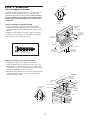
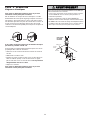
INSTALLATION STEP 7
Install the Light
• Press the release tabs on both sides of lens. Gently
rotate lens back and downward until the lens hinge is
in the fully open position. Do not remove the lens.
• Install a 100 watt maximum light bulb in the socket.
Light bulb size should be A19, standard neck only. The
light will turn ON and remain lit for approximately 4-1/2
minutes when power is connected. Then the light will
turn OFF.
• Reverse the procedure to close the lens.
• Use A19, standard neck garage door opener bulb for
replacement.
NOTE: Use only standard light bulbs. The use of short
neck or speciality light bulbs may overheat the endpanel
or light socket.
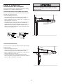
INSTALLATION STEP 8
Attach the Emergency Release Rope
and Handle
• Thread one end of the rope through the hole in the top
of the red handle so “NOTICE” reads right side up as
shown. Secure with an overhand knot at least 1" (2.5
cm) from the end of the rope to prevent slipping.
• Thread the other end of the rope through the hole in
the release arm of the outer trolley.
• Adjust rope length so the handle is 6 feet (1.83 m)
above the floor. Ensure that the rope and handle clear
the tops of all vehicles to avoid entanglement. Secure
with an overhand knot.
NOTE: If it is necessary to cut the rope, heat seal the cut
end with a match or lighter to prevent unraveling.
To prevent possible SERIOUS INJURY or DEATH from a
falling garage door:
• If possible, use emergency release handle to disengage
trolley ONLY when garage door is CLOSED. Weak or broken
springs or unbalanced door could result in an open door
falling rapidly and/or unexpectedly.
• NEVER use emergency release handle unless garage
doorway is clear of persons and obstructions.
• NEVER use handle to pull door open or closed. If rope knot
becomes untied, you could fall.
Lens
Hinge
Release Tab
100 Watt (Max)
Standard
Light Bulb
Trolley
Release arm
NOTICE
Emergency
Release Handle
Overhand
Knot
Trolley
WARNING
CAUTION
WARNING
WARNING
To prevent possible OVERHEATING of the endpanel or light
socket:
• DO NOT use short neck or specialty light bulbs.
• DO NOT use halogen bulbs. Use ONLY incandescent.
To prevent damage to the opener:
• DO NOT use bulbs larger than 100W.
• ONLY use A19 size bulbs.
WARNING
CAUTION
WARNING
WARNING

19
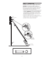
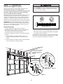
INSTALLATION STEP 9
Electrical Requirements
To avoid installation difficulties, do not run the
opener at this time.
To reduce the risk of electric shock, your garage door
opener has a grounding type plug with a third grounding
pin. This plug will only fit into a grounding type outlet. If
the plug doesn’t fit into the outlet you have, contact a
qualified electrician to install the proper outlet.
If permanent wiring is required by your local code,
refer to the following procedure.
To make a permanent connection through the 7/8" hole
in the top of the motor unit:
• Remove the motor unit cover screws and set the cover
aside.
• Remove the attached 3-prong cord.
• Connect the black (line) wire to the screw on the brass
terminal; the white (neutral) wire to the screw on the
silver terminal; and the ground wire to the green
ground screw. The opener must be grounded.
• Reinstall the cover.
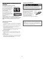
To avoid installation difficulties, do not run the
opener at this time.
RIGHT
WRONG
To prevent possible SERIOUS INJURY or DEATH from
electrocution or fire:
• Be sure power is not connected to the opener, and
disconnect power to circuit BEFORE removing cover to
establish permanent wiring connection.
• Garage door installation and wiring MUST be in compliance
with all local electrical and building codes.
• NEVER use an extension cord, 2-wire adapter, or change
plug in any way to make it fit outlet. Be sure the opener is
grounded.
Ground Tab
Green
Ground Screw
Ground Wire
Black Wire
PERMANENT WIRING
CONNECTION
White Wire
Black
Wire
WARNING
CAUTION
WARNING
WARNING

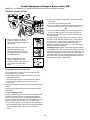
20
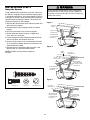
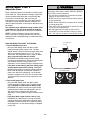
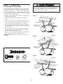
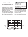
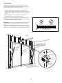
Invisible Light Beam
Protection Area
Safety Reversing Sensor
6" (15 cm) max. above floor
Safety Reversing Sensor
6" (15 cm) max. above floor
Facing the door from inside the garage
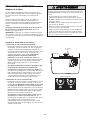
INSTALLATION STEP 10
Install The Protector System
®
The safety reversing sensor must be connected and
aligned correctly before the garage door opener will
move in the down direction.
IMPORTANT INFORMATION ABOUT
THE SAFETY REVERSING SENSOR
When properly connected and aligned, the sensor will
detect an obstacle in the path of its electronic beam. The
sending eye (with an amber indicator light) transmits an
invisible light beam to the receiving eye (with a green
indicator light). If an obstruction breaks the light beam
while the door is closing, the door will stop and reverse
to full open position, and the opener lights will flash
10 times.
The units must be installed inside the garage so that the
sending and receiving eyes face each other across the
door, no more than 6" (15 cm) above the floor. Either can
be installed on the left or right of the door as long as the
sun never shines directly into the receiving eye lens.
The mounting brackets are designed to clip onto the
track of sectional garage doors without additional
hardware.
If it is necessary to mount the units on the wall, the
brackets must be securely fastened to a solid surface
such as the wall framing. Extension brackets (see
accessories) are available if needed. If installing in
masonry construction, add a piece of wood at each
location to avoid drilling extra holes in masonry if
repositioning is necessary.
The invisible light beam path must be unobstructed. No
part of the garage door (or door tracks, springs, hinges,
rollers or other hardware) may interrupt the beam while
the door is closing.
Be sure power is not connected to the garage door opener
BEFORE installing the safety reversing sensor.
To prevent SERIOUS INJURY or DEATH from a closing
garage door:
• Correctly connect and align the safety reversing sensor.
This required safety device MUST NOT be disabled.
• Install the safety reversing sensor so beam is NO HIGHER
than 6" (15 cm) above garage floor.
WARNING
CAUTION
WARNING
WARNING
Page is loading ...
Page is loading ...
Page is loading ...
Page is loading ...
Page is loading ...
Page is loading ...
Page is loading ...
Page is loading ...
Page is loading ...
Page is loading ...
Page is loading ...
Page is loading ...
Page is loading ...
Page is loading ...
Page is loading ...
Page is loading ...
Page is loading ...
Page is loading ...
Page is loading ...
Page is loading ...
Page is loading ...
Page is loading ...
Page is loading ...
Page is loading ...
Page is loading ...
Page is loading ...
Page is loading ...
Page is loading ...
Page is loading ...
Page is loading ...
Page is loading ...
Page is loading ...
Page is loading ...
Page is loading ...
Page is loading ...
Page is loading ...
Page is loading ...
Page is loading ...
Page is loading ...
Page is loading ...
Page is loading ...
Page is loading ...
Page is loading ...
Page is loading ...
Page is loading ...
Page is loading ...
Page is loading ...
Page is loading ...
Page is loading ...
Page is loading ...
Page is loading ...
Page is loading ...
Page is loading ...
Page is loading ...
Page is loading ...
Page is loading ...
Page is loading ...
Page is loading ...
Page is loading ...
Page is loading ...
-
 1
1
-
 2
2
-
 3
3
-
 4
4
-
 5
5
-
 6
6
-
 7
7
-
 8
8
-
 9
9
-
 10
10
-
 11
11
-
 12
12
-
 13
13
-
 14
14
-
 15
15
-
 16
16
-
 17
17
-
 18
18
-
 19
19
-
 20
20
-
 21
21
-
 22
22
-
 23
23
-
 24
24
-
 25
25
-
 26
26
-
 27
27
-
 28
28
-
 29
29
-
 30
30
-
 31
31
-
 32
32
-
 33
33
-
 34
34
-
 35
35
-
 36
36
-
 37
37
-
 38
38
-
 39
39
-
 40
40
-
 41
41
-
 42
42
-
 43
43
-
 44
44
-
 45
45
-
 46
46
-
 47
47
-
 48
48
-
 49
49
-
 50
50
-
 51
51
-
 52
52
-
 53
53
-
 54
54
-
 55
55
-
 56
56
-
 57
57
-
 58
58
-
 59
59
-
 60
60
-
 61
61
-
 62
62
-
 63
63
-
 64
64
-
 65
65
-
 66
66
-
 67
67
-
 68
68
-
 69
69
-
 70
70
-
 71
71
-
 72
72
-
 73
73
-
 74
74
-
 75
75
-
 76
76
-
 77
77
-
 78
78
-
 79
79
-
 80
80


Craftsman 139.18452D User manual
- Category
- Garage Door Opener
- Type
- User manual
- This manual is also suitable for
Ask a question and I''ll find the answer in the document
Finding information in a document is now easier with AI
in other languages
- français: Craftsman 139.18452D Manuel utilisateur
Related papers
-
Craftsman 13953962SRT Owner's manual
-
-
-
-
-
-
-
-
-
Other documents
-
Chamberlain CG40CD User manual
-
-
 Security + Elite 3575CS User manual
-
-
-
Chamberlain C870 User manual
-
Sears 139.53930D Owner's manual
-
-
-
