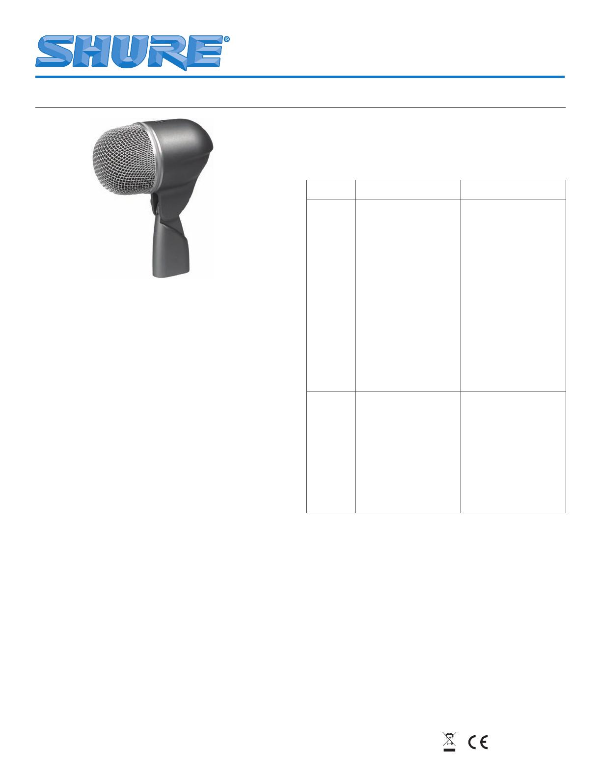
Model BETA 52
®
A User Guide
27D2799 (Rev. 5) Printed in U.S.A.
©2005, Shure Incorporated
SUPERCARDIOID DYNAMIC INSTRUMENT
MICROPHONE
GENERAL
The Shure BETA 52
®
A is a high output dynamic microphone
with a tailored frequency response designed specifically for kick
drums and other bass instruments. It provides superb attack and
“punch,” and delivers studio quality sound even at extremely high
sound pressure levels.
The BETA 52A features a modified supercardioid pattern through
-
out its frequency range to insure high gain before feedback and
excellent rejection of unwanted sound. A built–in dynamic locking
stand adapter with an integral XLR connector simplifies installa
-
tion, particularly if the microphone is to be placed inside a kick
drum. The stand adapter keeps the microphone position fixed and
resists slipping, even when subjected to sharp blows and strong
vibrations. A hardened steel mesh grille protects the BETA 52A
from the abuse and wear associated with touring.
FEATURES
Frequency response shaped specifically for kick drums
and bass instruments
Built–in dynamic locking stand adapter with integral XLR
connector simplifies setup, especially inside a kick drum
Studio quality performance, even at extremely high sound
pressure levels
Supercardioid pattern for high gain before feedback and
superior rejection of unwanted noise
Hardened steel mesh grille that resists wear and abuse
Advanced pneumatic shock mount system that minimizes
transmission of mechanical noise and vibration
Neodymium magnet for high signal–to–noise ratio output
Low sensitivity to varying load impedance
Legendary Shure quality and reliability
•
•
•
•
•
•
•
•
•
APPLICATIONS AND PLACEMENT
The most common BETA 52A applications and placement tech-
niques are listed in the following table. Keep in mind that micro-
phone technique is largely a matter of personal taste– there is no
one “correct” microphone position.
Application Suggested Microphone
Placement
Tone Quality
Kick Drum
5 to 7.5 cm (2 to 3 in.) away
from beater head, slightly
off-center from beater.
Sharp attack; maximum
bass sound, highest sound
pressure level.
20 to 30 cm (8 to 12 in.)
from beater head, on-axis
with beater.
Medium attack; balanced
sound.
20 to 30 cm (8 to 12 in.)
from beater head, 15 to 20
cm (6 to 8 in.) from edge
of head.
Medium attack; thin, re-
duced bass sound.
5 to 7.5 cm (2 to 3 in.) away
from outside head, on-axis
with beater (double head
kickdrum only).
Softer attack; balanced,
resonant sound.
NOTE: To “tighten” the
beat, place a pillow or
blanket on bottom of drum
against beater head.
Electric
Bass Ampli-
fier
2.5 cm (1 in.) from speaker,
on-axis with center of
speaker cone.
Sharp attack; emphasized
bass.
2.5 cm (1 in.) from speaker,
at edge of speaker cone.
Sharp attack; higher fre-
quency sound.
10 to 15 cm (4 to 6 in.) from
speaker, on-axis with center
of speaker cone.
Sharp attack; full, balanced
sound.
60 to 90 cm (2 to 3 ft.) from
speaker, on-axis with center
of speaker cone.
Soft attack; mellow, higher
frequency sound.
MOUNTING THE BETA 52A ON A MICROPHONE STAND
The built–in stand adapter features a dynamic locking system
that permits adjustments to the microphone’s position, but resists
slipping when struck or bumped. To mount the BETA 52A on a
stand and adjust its position, proceed as follows:
Screw the integral stand adapter onto the end of a micro-
phone stand (see Figure 3). Adjust the stand height and
position as necessary.
Pivot the BETA 52A until it is in the desired position rela
-
tive to the drum head or loudspeaker.
Lock the BETA 52A in place by rotating the adjustment
knob on the stand adapter clockwise until it is tight. Do
NOT overtighten the knob with tools.
If necessary, make minor adjustments to the microphone
position without loosening the adjustment knob.
Connect an audio cable to the integral XLR connector.
1.
2.
3.
4.
5.
MODEL BETA 52
®
A


