Simplicity 01928-1 User manual
- Category
- Power generators
- Type
- User manual
Page is loading ...

2
Briggs & Stratton Power Products Automatic Transfer Switch
Installation and Operator’s Manual
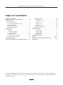
TABLE OF CONTENTS
TABLE OF CONTENTS . . . . . . . . . . . . . . . . . . . . . . . . . . . 2
IMPORTANT SAFETY INSTRUCTIONS . . . . . . . . . . . . . . 3
INTRODUCTION. . . . . . . . . . . . . . . . . . . . . . . . . . . . . . . . 4
For the Home Owner: . . . . . . . . . . . . . . . . . . . . . . . . 4
For the Installing Dealer/Contractor: . . . . . . . . . . . . . 4
Owner Orientation . . . . . . . . . . . . . . . . . . . . . . . . . . . 5
Installer Responsibilities . . . . . . . . . . . . . . . . . . . . . . . . 5
Equipment Description. . . . . . . . . . . . . . . . . . . . . . . . . 5
INSTALLATION. . . . . . . . . . . . . . . . . . . . . . . . . . . . . . . . . . 6
Unpacking . . . . . . . . . . . . . . . . . . . . . . . . . . . . . . . . . . . 6
Delivery Inspection . . . . . . . . . . . . . . . . . . . . . . . . 6
Shipment Contents . . . . . . . . . . . . . . . . . . . . . . . . 6
Mounting Guidelines . . . . . . . . . . . . . . . . . . . . . . . . . 6-7
Power Wiring Interconnections . . . . . . . . . . . . . . . . 8-9
Supervisory Control Wiring. . . . . . . . . . . . . . . . . . . . . 8
SYSTEM OPERATION. . . . . . . . . . . . . . . . . . . . . . . . . . . . 10
TESTING THE AUTOMATIC TRANSFER SWITCH . . . 10
Automatic Sequence. . . . . . . . . . . . . . . . . . . . . . . . . . 10
Utility Fail. . . . . . . . . . . . . . . . . . . . . . . . . . . . . . . 10
Engine Warm-Up . . . . . . . . . . . . . . . . . . . . . . . . . 10
Transfer . . . . . . . . . . . . . . . . . . . . . . . . . . . . . . . . 10
Utility Pickup . . . . . . . . . . . . . . . . . . . . . . . . . . . . 10
Retransfer . . . . . . . . . . . . . . . . . . . . . . . . . . . . . . 10
Engine Cool Down . . . . . . . . . . . . . . . . . . . . . . . 10
When Calling The Factory . . . . . . . . . . . . . . . . . . . . . 10
SPECIFICATIONS . . . . . . . . . . . . . . . . . . . . . . . . . . . . . . . 11
Model 01813-1 . . . . . . . . . . . . . . . . . . . . . . . . . . 11
Model 01814-1 . . . . . . . . . . . . . . . . . . . . . . . . . . 11
Model 01928-1 . . . . . . . . . . . . . . . . . . . . . . . . . . 11
Model 01929-1 . . . . . . . . . . . . . . . . . . . . . . . . . . 11
TROUBLESHOOTING . . . . . . . . . . . . . . . . . . . . . . . . . . . 12
NOTES . . . . . . . . . . . . . . . . . . . . . . . . . . . . . . . . . . 13 & 20
DIAGRAMS, EXPLODED VIEWS, PARTS LISTS . . . . . 14-19
WARRANTY . . . . . . . . . . . . . . . . . . . . . . . . . . . . . . . . . . . 21
Copyright © 2007 Briggs & Stratton Power Products Group, LLC. All rights reserved. No part of this material may be
reproduced or transmitted in any form by any means without the express written permission of Briggs & Stratton Power
Products Group, LLC.

3
Briggs & Stratton Power Products Automatic Transfer Switch
Installation and Operator’s Manual
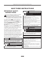
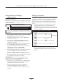
IMPORTANT SAFETY
INSTRUCTIONS
This is the safety alert symbol. It is used to
alert you to potential personal injury
hazards. Obey all safety messages that follow
this symbol to avoid possible injury or death.
The safety alert symbol ( ) is used with a signal word
(DANGER, CAUTION,WARNING), a pictorial and/or a
safety message to alert you to hazards. DANGER indicates
a hazard which, if not avoided, will result in death or
serious injury. WARNING indicates a hazard which, if not
avoided, could result in death or serious injury.
CAUTION indicates a hazard which, if not avoided, might
result in minor or moderate injury. CAUTION, when
used without the alert symbol, indicates a situation that
could result in equipment damage. Follow safety messages
to avoid or reduce the risk of injury or death.
The manufacturer cannot possibly anticipate every possible
circumstance that might involve a hazard.The warnings in
this manual, and the tags and decals affixed to the unit are,
therefore, not all-inclusive. If you use a procedure, work
method or operating technique that the manufacturer does
not specifically recommend, you must satisfy yourself that it
is safe for you and others.You must also make sure that the
procedure, work method or operating technique that you
choose does not render the transfer switch unsafe.
• DO NOT touch bare wires or receptacles.
• DO NOT use transfer switch with worn, frayed, bare or
otherwise damaged wiring.
• DO NOT handle electrical cords while standing in water,
while barefoot, or while hands or feet are wet.
• If you must work around a unit while it is operating, stand on
an insulated dry surface to reduce shock hazard.
• DO NOT allow unqualified persons or children to operate or
service transfer switch.
• In case of an accident caused by electrical shock, immediately
shut down the source of electrical power and contact local
authorities. Avoid direct contact with the victim.
Failure to properly ground transfer switch can
result in electrocution.
WARNING
• Use transfer switch only for intended uses.
• If you have questions about intended use, ask dealer or
contact Briggs and Stratton Power Products.
• DO NOT expose transfer switch to excessive moisture, dust,
dirt, or corrosive vapors.
• Remain alert at all times while working on this equipment.
NEVER work on the equipment when you are physically or
mentally fatigued.
• If connected devices overheat, turn them off and turn off their
circuit breaker/fuse.
Improper treatment of transfer switch can damage it
and shorten its life.
CAUTION
• Despite the safe design of the transfer switch, operating this
equipment imprudently, neglecting its maintenance or being
careless can cause possible injury or death.
Transfer Switch contains high voltage that can
cause personal injury or death.
WARNING
• Failure to follow above warning could cause personal injury,
damage and/or malfunction of equipment.
Low voltage wire cannot be installed in same
conduit as power voltage wiring.
WARNING
Only qualified electricians should attempt installation
of this system, which must strictly comply with
applicable codes, standards and regulations.
WARNING
SAVE THESE INSTRUCTIONS

4
Briggs & Stratton Power Products Automatic Transfer Switch
Installation and Operator’s Manual
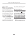
INTRODUCTION
Thank you for your purchase of this Briggs & Stratton
Power Products Automatic Transfer Switch.This product is
intended for use with Briggs & Stratton Home Standby
Generator sets ONLY.This is an optional home standby
system which provides an alternate source of electric
power and to serve loads such as a gas furnace,
refrigeration and communication systems that, when
stopped during any power outage, could cause discomfort,
or the like.This product DOES NOT qualify for emergency
standby as defined by NFPA 70 (NEC).
Briggs and Stratton Power Products (BSPP) has made every
effort to provide for a safe, streamlined and cost-effective
installation. Each installation is unique, it is impossible to
know of and advise of all conceivable procedures and
methods by which installation might be achieved.We do
not know all possible hazards and/or the results of each
method or procedure. For these reasons,
Only licensed electrical contractors
should install transfer switches.
Installations must strictly comply with all
applicable federal, state and local codes,
standards and regulations.
Your BSPP Transfer Switch is supplied with this combined
“Installation and Operator’s Manual”.This is an important
document and should be retained by the owner after the
installation has been completed.
Every effort has been expended to make sure that the
information in this manual is both accurate and current.
However, the manufacturer reserves the right to change,
alter or otherwise improve the system at any time without
prior notice.
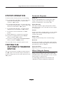
For the Home Owner
To help you make informed choices and communicate
effectively with your installation contractor(s),
Read and understand the
Owner Orientation Section of this manual
BEFORE
contracting or starting
your transfer switch installation.
To arrange for proper installation, contact the store at
which you purchased your BSPP Transfer Switch, your
dealer, or your utility power provider.
The Transfer Switch Warranty is V
OID
unless the system is installed by a
licensed electrical professional.
For the Installing Dealer/Contractor
Check federal, state and local codes for questions on
installation.
If you need more information about the transfer switch,
call 1-800-743-4115, between 8:00 AM and 5:00 PM CT.

5
Briggs & Stratton Power Products Automatic Transfer Switch
Installation and Operator’s Manual
Owner Orientation
The illustrations are for typical circumstances and are
meant to familiarize you with the installation options
available with your transfer switch.
Local codes, appearance, and distances are the factors that
must be considered when negotiating with an installation
professional.As the distance from the existing electrical
service increases, compensation in wiring materials must be
allowed for.This is necessary to comply with local codes
and overcome electrical voltage drops.
The factors mentioned above will have a direct effect
on the overall price of your transfer switch installation.
NOTE: Your installer must check local codes AND obtain
permits before installing the system.
• Read and follow the instructions given in this manual.
• Follow a regular schedule in caring for and using your
transfer switch, as specified in the manual.
Installer Responsibilities
• Read and observe the safety rules.
• Read and follow the instructions given in this manual.
• Check federal, state and local codes.
• Ensure generator is not overloaded with selected loads.
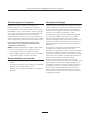
Equipment Description
The transfer switches are intended to transfer the entire
load of normal residential installations when used with the
supervisory contacts provided.The load is connected either
to utility power (normal) or home standby power
(generator).The transfer switch monitors utility and
generator voltages and will automatically connect to the
appropriate source of power.
Major components of the transfer switch are a 2 pole
disconnect circuit breaker (models 01928-1 & 01929-1
only), a 2 pole double throw transfer switch, control circuit
board, fused utility terminals and interconnecting wiring.
The transfer switch is solenoid-operated from utility or
generator inputs and contain suitable mechanical and
electrical interlock switches to eliminate the possibility of
connecting the utility service to the generator output. It
has ratings capable of switching full utility power into the
residence. In addition, a manual override lever is provided
for the transfer function.
The control circuit board has active circuits sensing utility
and generator voltages. It creates a signal for the generator
start-up, switch transfer, retransfer when utility is restored
and generator cool down periods.The control board also
contains red and green LED’s indicating the power sources
available and two relay operated contacts that provide
supervisory control of external loads.

6
Briggs & Stratton Power Products Automatic Transfer Switch
Installation and Operator’s Manual
INSTALLATION
Unpacking
Delivery Inspection
After removing the carton, carefully inspect the transfer
switch components for any damage that may have occurred
during shipment.
IMPORTANT: If loss or damage is noted at time of
delivery, have the person(s) making delivery note all damage
on the freight bill and affix his signature under the
consignor's memo of loss or damage. If loss or damage is
noted after delivery, contact the carrier for claim
procedures. Missing or damaged parts are not warranted.
Shipment Contents
• Automatic Power Transfer Switch
• Installation and Operator’s Manual
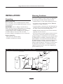
Mounting Guidelines
The Automatic Transfer Switch is enclosed in a NEMA Type
3R enclosure suitable for indoor/outdoor use. Guidelines
for mounting the Automatic Transfer Switch include:
• Install the switch on a firm, sturdy supporting structure.
• The switch must be installed with minimum NEMA 3R
hardware for conduit connections.
• To prevent switch contact distortion, level and plumb the
enclosure.This can be done by placing washers between
the switch enclosure and the mounting surface.
• NEVER install the switch where any corrosive substance
might drip onto the enclosure.
• Protect the switch at all times against excessive moisture,
dust, dirt, lint, construction grit and corrosive vapors.
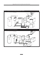
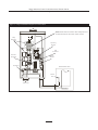
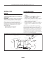
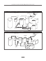
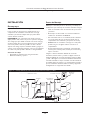
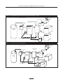
A typical installation of the Automatic Power Transfer Switch
for Models 01813-1 and 01814-1 is depicted in Figure 1.A
typical installation of the Automatic Power Transfer Switch
for Models 01928-1 and 01929-1 is depicted in Figure 2.An
alternative installation of the Automatic Power Transfer
Switch is depicted in Figure 3. It is best if it is mounted near
the utility meter, either inside or outside. Discuss layout
suggestions/changes with the owner before beginning the
system installation process.
Figure 1 — A Typical Transfer Switch Mounting for Models 01813-1 & 01814-1
Main
Breaker
Panel
Transfer
Switch
Hot
Water
Heater
Air
Conditioner
Contactor
Service Disconnect
Generator
Watt -
Hourmeter
Branch Circuits
— — — — — — Control Wiring
Disconnect Switch

7
Briggs & Stratton Power Products Automatic Transfer Switch
Installation and Operator’s Manual
Figure 3 — An Alternate Transfer Switch Mounting
Main
Breaker
Panel
Transfer
Switch
Hot
Water
Heater
Air
Conditioner
Contactor
Disconnect Switch
Generator
Watt -
Hourmeter
Branch Circuits
— — — — — — Control Wiring
Emergency
Load Center
Figure 2 — A Typical Transfer Switch Mounting for Models 01928-1 & 01929-1
Main
Breaker
Panel
Transfer
Switch
w/Utility
Disconnect
Circuit
Breaker
Hot
Water
Heater
Air
Conditioner
Contactor
Service Disconnect
Generator
Watt -
Hourmeter
Branch Circuits
— — — — — — Control Wiring
Disconnect Switch

8
Briggs & Stratton Power Products Automatic Transfer Switch
Installation and Operator’s Manual
Power Wiring Interconnections
All wiring must be the proper size, properly supported and
protected by conduit.
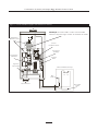
Complete the following connections between the transfer
switch, main distribution panel, utility power and generator
(Figure 4, on next page).
1. Ensure utility power is turned OFF. Connect utility
power supply leads to transfer switch terminals
marked “UTILITY CONNECTION”.
2. Connect utility neutral to the transfer switch
“NEUTRAL” terminal.
3. Connect main distribution panel power leads to transfer
switch terminals marked “LOAD CONNECTION”.
4. Connect main distribution panel neutral lead to
transfer switch “NEUTRAL” terminal.
5. Connect generator power supply leads from the
generator’s control panel to transfer switch terminals
marked “GENERATOR CONNECTION”.
6. Connect generator Neutral from the control panel to
the transfer switch “NEUTRAL” terminal.
7. Connect generator “GND” from the control panel to
the transfer switch “GND” terminal.
8. Connect main distribution panel “GND” to the
transfer switch “GND” terminal.
NOTE: Assure grounding electrode conductor is
connected and bonded per applicable federal, state and
local codes, standards and regulations.
9. Connect generator utility 240 VAC terminals to
transfer switch utility 240 VAC terminals.
10. Tighten all wire connections/fasteners to proper
torque. See inside transfer switch enclosure for proper
torque values.
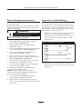
Supervisory Control Wiring
Terminal strip on control module in transfer switch has
four connections for customer use.There are two sets of
“Normally Closed” contacts available.They will be opened
when generator power is required.These can be used to
lock out large loads when powered by generator. Example:
air conditioner, hot water heater, etc..
1. Terminals on control module are for installer supplied
contactors to lock out large loads. Example: air
conditioner, electric hot water heater, etc.. Contacts
are connected in series with the contactor control
circuit (Figure 5).
2. Tighten all wire connections/fasteners to proper
torque. See inside transfer switch enclosure for proper
torque values.
• Failure to follow above warning could cause personal injury,
damage and/or malfunction of equipment.
Low voltage wire cannot be installed in same
conduit as power voltage wiring.
WARNING
Figure 5 — Terminals on Control Module
Air Conditioner Contactor
Supply
Contactor
Neutral
120 VAC

9
Briggs & Stratton Power Products Automatic Transfer Switch
Installation and Operator’s Manual
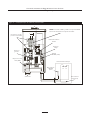
Figure 4 — A Typical Installation Diagram for Transfer Switch
Main
Main Distribution Panel
Ground Bus
Neutral
Bus
To Generator
Neutral
Terminal
To Utility Power
Supervisory
Contacts
Load
Connection
Ground Lug
Generator
Connection
Utility
Connection
NOTE: Models 01928-1 and 01929-1 have a utility disconnect
circuit breaker built into the transfer switch enclosure.

10
Briggs & Stratton Power Products Automatic Transfer Switch
Installation and Operator’s Manual
SYSTEM OPERATION
To select automatic transfer operation, do the following:
1A. For models 01813-1 & 01814-1, set service disconnect
switch that sends utility power to transfer switch
contactor to “On” position.
B. For models 01928-1 & 01929-1, set service disconnect
switch that sends utility power to transfer switch utility
disconnect circuit breaker to “On” position.
2. For models 01928-1 & 01929-1, set transfer switch
utility disconnect circuit breaker to “On” position.
3. Set generator’s main circuit breaker to its “On”
position.
4. Install 15 Amp fuse in control panel on generator.
5A. If generator is equipped with a system ON/OFF
switch, set switch to “On” position.
B. If generator is equipped with a AUTO/OFF/MANUAL
switch, set switch to “AUTO” position.
The system will now be in automatic operation mode.
TESTING THE
AUTOMATIC TRANSFER
SWITCH
Turn the service disconnect feeding the transfer switch, to
the “Off” position.The automatic sequence will follow.To
go back to utility power, turn the service disconnect to the
“On” position.
Automatic Sequence
Utility Fail
The Home Standby Generator set senses when utility
voltage is below 70 percent of nominal. Engine start
sequence is initiated after 6 second time delay.
Engine Warm-Up
Time delay to allow for engine warm-up before transfer
fixed at 20 seconds or 50 seconds with removal of jumper
on control board.
Transfer
Transfer from utility to standby supply occurs after standby
voltage is above set levels. Minimum engine run time is
5 minutes after transfer.
Utility Pickup
Voltage pickup level is 80 percent of nominal voltage.
Retransfer
Retransfer from standby to utility supply is approximately
10 seconds after utility voltage supply is above pickup level
and minimum run time is completed.
Engine Cool Down
Engine will run for 60 seconds after retransfer.
When Calling the Factory
Before contacting Briggs and Stratton Power Products
regarding service or repair of this transfer switch, obtain
the Model Number and Serial Number from the unit data
decal located on or inside the case.
To contact Briggs and Stratton Power Products call
1-800-743-4115, between 8:00 AM and 5:00 PM CT.

11
Briggs & Stratton Power Products Automatic Transfer Switch
Installation and Operator’s Manual
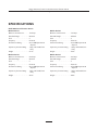
SPECIFICATIONS
UL® 1008 Listed Transfer Switch
Model 01813-1
Maximum Load Current:. . . . . . . 100 Amps
Rated AC Voltage. . . . . . . . . . . . . 250 Volts
Poles . . . . . . . . . . . . . . . . . . . . . . 2
Frequency . . . . . . . . . . . . . . . . . . 50/60 Hz
Fault Current Rating . . . . . . . . . . 22,000 RMS Symmetrical
Amperes
Supervisory Contacts Rating . . . 1 Amp, 125 Volt AC, Pilot
Duty
Weight . . . . . . . . . . . . . . . . . . . . . 21 lbs.
Model 01814-1
Maximum Load Current:. . . . . . . 200 Amps
Rated AC Voltage. . . . . . . . . . . . . 250 Volts
Poles . . . . . . . . . . . . . . . . . . . . . . 2
Frequency . . . . . . . . . . . . . . . . . . 50/60 Hz
Fault Current Rating . . . . . . . . . . 25,000 RMS Symmetrical
Amperes
Supervisory Contacts Rating . . . 1 Amp, 125 Volt AC, Pilot
Duty
Weight . . . . . . . . . . . . . . . . . . . . . 34 lbs.
Model 01928-1
Maximum Load Current:. . . . . . . 100 Amps
Rated AC Voltage. . . . . . . . . . . . . 250 Volts
Poles . . . . . . . . . . . . . . . . . . . . . . 2
Frequency . . . . . . . . . . . . . . . . . . 50/60 Hz
Fault Current Rating . . . . . . . . . . 22,000 RMS Symmetrical
Amperes
Supervisory Contacts Rating . . . 1 Amp, 125 Volt AC, Pilot
Duty
Weight . . . . . . . . . . . . . . . . . . . . . 32 lbs.
Model 01929-1
Maximum Load Current:. . . . . . . 200 Amps
Rated AC Voltage. . . . . . . . . . . . . 250 Volts
Poles . . . . . . . . . . . . . . . . . . . . . . 2
Frequency . . . . . . . . . . . . . . . . . . 50/60 Hz
Fault Current Rating . . . . . . . . . . 25,000 RMS Symmetrical
Amperes
Supervisory Contacts Rating . . . 1 Amp, 125 Volt AC, Pilot
Duty
Weight . . . . . . . . . . . . . . . . . . . . . 44 lbs.

12
Briggs & Stratton Power Products Automatic Transfer Switch
Installation and Operator’s Manual
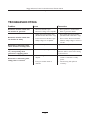
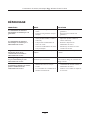
TROUBLESHOOTING
Problem Cause Correction
Automatic transfer switch does
not transfer to generator
1. Generator breaker open.
2. Generator voltage not acceptable.
1. Reset generator circuit breaker.
2. Refer to generator manual.
Automatic transfer switch does
not transfer to utility
1. Utility disconnect breaker open
(Models 01928-1 & 01929-1 only).
2. Service disconnect breaker open.
3. Utility voltage not acceptable.
1. Reset utility disconnect breaker
(Models 01928-1 & 01929-1 only).
2. Reset service disconnect breaker.
3. Wait for utility voltage to return to
normal.
Generator is still running after
switch transfers to utility power
Engine cool down period. Engine should stop after 1 minute.
Supervised loads (air conditioner,
etc.) are operating when
generator is supplying power
NC contacts not operating correctly. Check NC contacts for proper
operation and/or check control wiring
to external load.
Generator is still running after
utility power is restored
1. Minimum engine run time has not
elapsed.
2. Fuse(s) in transfer switch is
defective.
1. Wait five minutes for transfer
switch to retransfer to utility
power.
2. Check fuse(s) and replace if
necessary.

13
Briggs & Stratton Power Products Automatic Transfer Switch
Installation and Operator’s Manual
NOTES

14
Briggs & Stratton Power Products Automatic Transfer Switch
Installation and Operator’s Manual
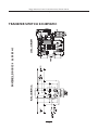
TRANSFER SWITCH SCHEMATIC
MODELS 01813-1 & 01814-1

15
Briggs & Stratton Power Products Automatic Transfer Switch
Installation and Operator’s Manual
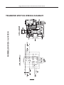
TRANSFER SWITCH WIRING DIAGRAM
MODELS 01928-1 & 01929-1

16
Briggs & Stratton Power Products Automatic Transfer Switch
Installation and Operator’s Manual
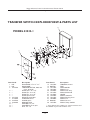
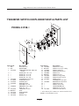
TRANSFER SWITCH EXPLODED VIEW & PARTS LIST
Item Part # Description
1 NSP ENCLOSURE, 16" x 12" x 6"
2 NSP BACK PANEL
3 195667GS TRANSFER SWITCH, 100A, with
Cover & Handle
4 * PPHMS, #10 - 32 x 1/2"
5 * PPHMS, #6 - 32 x 1/4"
6 * PPHMS, #6 - 32 x 1/2"
7 * PPHMS, #6-32 x 3/8"
8 193159GS DECAL, Reinstall After
9 191668GS CONTROL, Board
10 196353GS SPACER, Nylon
11 196094GS GROUND LUG
12 * WASHER, Lock 1/4"
13 * WASHER, Ext.Tooth, #10
14 * NUT, 1/4" - 20
Item Part # Description
15 192696GS TERMINAL, Neutral
16 B4857GS FUSE
17 192151GS FUSE HOLDER
19 198136GS DECAL, Logo
20 192702GS DECAL,Term Strip
21 192165GS DECAL,APPVD CB
22 192150GS SPACER
23 196522GS DECAL, 100A,ATS
25 190992GS DECAL,Warning Shock
26 190984GS DECAL, Fuse
27 B4986GS DECAL, Ground
28 192597GS DECAL, Utility, 240 VAC
* - Items without part numbers are common fasteners and
are available at your local hardware store.
MODEL 01813-1

17
Briggs & Stratton Power Products Automatic Transfer Switch
Installation and Operator’s Manual
TRANSFER SWITCH EXPLODED VIEW & PARTS LIST
Item Part # Description
1 NSP ENCLOSURE, 22” x 16” x 7”
2 NSP BACK PANEL
3 195668GS TRANSFER SWITCH, 200A, with
Cover & Handle
4 * PPHMS, #10 - 32 x 1/2"
5 * PPHMS, #6 - 32 x 1/4"
6 * PPHMS, #6 - 32 x 1/2"
7 * PPHMS, #6- 32 x 3/8"
8 193159GS DECAL, Reinstall After
9 191668GS CONTROL, Board
10 196353GS SPACER, Nylon
11 196094GS GROUND LUG
12 * WASHER, Lock 1/4"
13 * WASHER, Ext.Tooth, #10
14 * NUT, 1/4” - 20
Item Part # Description
15 192696GS TERMINAL, Neutral
16 B4857GS FUSE
17 192151GS FUSE HOLDER
19 198136GS DECAL, Logo
20 192702GS DECAL,Term Strip
21 192166GS DECAL,APPVD CB
22 192150GS SPACER
23 196523GS DECAL, 200A,ATS
25 190992GS DECAL,Warning Shock
26 190984GS DECAL, Fuse
27 B4986GS DECAL, Ground
28 192597GS DECAL, Utility 240VAC
* - Items without part numbers are common fasteners and
are available at your local hardware store.
MODEL 01814-1

18
Briggs & Stratton Power Products Automatic Transfer Switch
Installation and Operator’s Manual
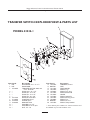
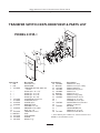
TRANSFER SWITCH EXPLODED VIEW & PARTS LIST
Item Part # Description
1 NSP ASSY, Enclosure
2 NSP BACK PANEL
3 195667GS TRANSFER SWITCH, 100A, with
Handle
4 * PPHMS, #10 - 32 x 1/2"
5 * PPHMS, #6 - 32 x 1/4"
6 * PPHMS, #6 - 32 x 1/2"
7 * PPHMS, #6- 32 x 3/8"
8 193664GS INSULATION, Dead Front
9 191668GS CONTROL, Board
10 196353GS SPACER, Nylon
11 196094GS GROUND LUG
12 * WASHER, Lock 1/4"
13 192882GS BREAKER Circuit, 100A
14 * NUT, 1/4” - 20
15 192696GS TERMINAL, Neutral
16 B4857GS FUSE
17 192151GS FUSE HOLDER
18 192150GS SPACER
19 198136GS DECAL, Logo
Item Part # Description
20 192702GS DECAL,Term Strip
21 B5106GS DECAL, Connection, Utility
23 196520GS DECAL, 100A,ATS
25 190992GS DECAL,Warning Shock
26 190984GS DECAL, Fuse
27 B4986GS DECAL, Ground
28 192597GS DECAL, Sensing, Utility
29 193450GS DECAL, Breaker, Circuit
30 193689GS WIRE, Copper
32 * WASHER, Ext.Tooth, #10
33 192770GS BRACKET, Circuit Breaker
34 * PPHMS, 8-32x 3/8"
35 * PPHMS, 10-32 x 3/8"
36 * LOCKWASHER, #10
37 * PPHMS, #10 - 32 x 1/4"
38 193159GS DECAL, Reinstall Barrier
* - Items without part numbers are common fasteners and
available at local hardware stores.
MODEL 01928-1

19
Briggs & Stratton Power Products Automatic Transfer Switch
Installation and Operator’s Manual
TRANSFER SWITCH EXPLODED VIEW & PARTS LIST
Item Part # Description
1 NSP ASSY, Enclosure
2 NSP BACK PANEL
3 195668GS TRANSFER SWITCH, 200A, with
Handle
4 * PPHMS, #10 - 32 x 1/2"
5 * PPHMS, #6 - 32 x 1/4"
6 * PPHMS, #6 - 32 x 1/2"
7 * PPHMS, #6- 32 x 3/8"
8 193664GS INSULATION, Dead Front
9 191668GS CONTROL, Board
10 196353GS SPACER, Nylon
11 196094GS GROUND LUG
12 * WASHER, Lock 1/4"
13 192065GS BREAKER Circuit, 200A
14 * NUT, 1/4” - 20
15 192696GS TERMINAL, Neutral
16 B4857GS FUSE
17 192151GS FUSE HOLDER
18 192150GS SPACER
19 198136GS DECAL, Logo
Item Part # Description
20 192702GS DECAL,Term Strip
21 B5106GS DECAL, Connection, Utility
23 196521GS DECAL, 200A,ATS
25 190992GS DECAL,Warning Shock
26 190984GS DECAL, Fuse
27 B4986GS DECAL, Ground
28 192597GS DECAL, Sensing, Utility
29 193450GS DECAL, Breaker, Circuit
30 * PPHMS, #10 - 32 x 3/4"
32 * WASHER, Ext.Tooth, #10
33 192879GS INSULATION, Circuit Breaker
34 * PPHMS, 1/4-20x 3/4"
35 192881GS BUS BAR
36 * LOCKWASHER, #10
37 * PPHMS, #10 - 32 x 1/4"
38 193159GS DECAL, Reinstall Barrier
* - Items without part numbers are common fasteners and
available at local hardware stores.
MODEL 01929-1

20
Briggs & Stratton Power Products Automatic Transfer Switch
Installation and Operator’s Manual
NOTES

BRIGGS & STRATTON POWER PRODUCTS GROUP, LLC TRANSFER SWITCH OWNER WARRANTY POLICY
LIMITED WARRANTY
Briggs & Stratton Power Products Group, LLC will repair or replace, free of charge, any part(s) of the equipment that is defective in material or
workmanship or both.Transportation charges on product submitted for repair or replacement under this warranty must be borne by purchaser.
This warranty is effective for the time periods and subject to the conditions stated below. For warranty service, find the nearest Authorized Service
Dealer in our dealer locator map at BRIGGSandSTRATTON.COM.
THERE IS NO OTHER EXPRESS WARRANTY. IMPLIED WARRANTIES, INCLUDING THOSE OF MERCHANTABILITY AND FITNESS FOR A
PARTICULAR PURPOSE,ARE LIMITED TO ONE YEAR FROM PURCHASE, OR TO THE EXTENT PERMITTED BY LAW. ANY AND ALL IMPLIED
WARRANTIES ARE EXCLUDED. LIABILITY FOR INCIDENTAL OR CONSEQUENTIAL DAMAGES ARE EXCLUDED TO THE EXTENT
EXCLUSION IS PERMITTED BY LAW. Some states or countries do not allow limitations on how long an implied warranty lasts, and some states or
countries do not allow the exclusion or limitation of incidental or consequential damages, so the above limitation and exclusion may not apply to
you.This warranty gives you specific legal rights and you may also have other rights which vary from state to state or country to country.
3 years
None
Consumer Use
Commercial Use
The warranty period begins on the date of purchase by the first retail consumer or commercial end user, and continues for the period of time stated in
the table above.“Consumer use" means personal residential household use by a retail consumer.“Commercial use" means all other uses, including use for
commercial, income producing or rental purposes. Once equipment has experienced commercial use, it shall thereafter be considered as commercial use
for purposes of this warranty. Equipment used for prime power in place of utility are not applicable to this warranty.
NO WARRANTY REGISTRATION IS NECESSARY TO OBTAIN WARRANTY ON BRIGGS & STRATTON PRODUCTS. SAVE YOUR PROOF OF
PURCHASE RECEIPT. IF YOU DO NOT PROVIDE PROOF OF THE INITIAL PURCHASE DATE AT THE TIME WARRANTY SERVICE IS REQUESTED,
THE MANUFACTURING DATE OF THE PRODUCT WILL BE USED TO DETERMINE THE WARRANTY PERIOD.
ABOUT YOUR WARRANTY
We welcome warranty repair and apologize to you for being inconvenienced.Any Authorized Service Dealer may perform warranty repairs. Most
warranty repairs are handled routinely, but sometimes requests for warranty service may not be appropriate. For example, warranty service would not
apply if equipment damage occurred because of misuse, lack of routine maintenance, shipping, handling, warehousing or improper installation. Similarly, the
warranty is void if the manufacturing date or the serial number on the equipment has been removed or the equipment has been altered or modified.
During the warranty period, the Authorized Service Dealer, at its option, will repair or replace any part that, upon examination, is found to be defective
under normal use and service.This warranty will not cover the following repairs and equipment:
• Normal Wear: Outdoor Power Equipment, like all mechanical devices, needs periodic parts and service to perform well.This warranty does not
cover repair when normal use has exhausted the life of a part or the equipment.
• Installation and Maintenance:This warranty does not apply to equipment or parts that have been subjected to improper or unauthorized
installation or alteration and modification, misuse, negligence, accident, overloading, improper maintenance, repair or storage so as, in our judgment,
to adversely affect its performance and reliability.This warranty also does not cover normal maintenance such as adjustments, cleaning and fuse
replacement.
• Other Exclusions:This warranty excludes wear items or damage or malfunctions resulting from accidents, abuse, modifications, alterations, or
improper servicing.Accessory parts are excluded from the product warranty.This warranty excludes failures due to acts of God and other force
majeure events beyond the manufacturers control.Also excluded is used, reconditioned, and demonstration equipment.
198180E, Rev. C, 12/31/2006
BRIGGS & STRATTON POWER PRODUCTS GROUP, LLC
JEFFERSON,WI, USA
Effective November 1, 2005 replaces all undated Warranties and all Warranties dated before November 1, 2005
WARRANTY PERIOD
Page is loading ...
Page is loading ...
Page is loading ...
Page is loading ...
Page is loading ...
Page is loading ...
Page is loading ...
Page is loading ...
Page is loading ...
Page is loading ...
Page is loading ...
Page is loading ...
Page is loading ...
Page is loading ...
Page is loading ...
Page is loading ...
Page is loading ...
Page is loading ...
Page is loading ...
Page is loading ...
Page is loading ...
Page is loading ...
Page is loading ...
-
 1
1
-
 2
2
-
 3
3
-
 4
4
-
 5
5
-
 6
6
-
 7
7
-
 8
8
-
 9
9
-
 10
10
-
 11
11
-
 12
12
-
 13
13
-
 14
14
-
 15
15
-
 16
16
-
 17
17
-
 18
18
-
 19
19
-
 20
20
-
 21
21
-
 22
22
-
 23
23
-
 24
24
-
 25
25
-
 26
26
-
 27
27
-
 28
28
-
 29
29
-
 30
30
-
 31
31
-
 32
32
-
 33
33
-
 34
34
-
 35
35
-
 36
36
-
 37
37
-
 38
38
-
 39
39
-
 40
40
-
 41
41
-
 42
42
-
 43
43
-
 44
44


Simplicity 01928-1 User manual
- Category
- Power generators
- Type
- User manual
Ask a question and I''ll find the answer in the document
Finding information in a document is now easier with AI
in other languages
- français: Simplicity 01928-1 Manuel utilisateur
- español: Simplicity 01928-1 Manual de usuario
Related papers
-
Simplicity 040308GEC-0 User manual
-
-
-
Briggs & Stratton 071037 User manual
-
-
-
Simplicity 040344-00 User manual
-
-
-
Other documents
-
-
-
-
-
-
-
Briggs & Stratton 71018 User manual
-
-
-