Page is loading ...

2
LIMITED WARRANTY
Bercomac Limitée
92, Fortin Nord, Adstock, Québec, Canada, G0N 1S0
Conditions and Products Covered:
BERCOMAC guarantees any part of the product or accessory
manufactured by BERCOMAC and found in the reasonable
judgment of BERCOMAC to be defective in material and or
workmanship will be repaired or replaced by an authorized
dealer without charge up to our maximum labor rates and pre-
established times. For replacement parts only standard
ground freight services are covered. This warranty extends to
the original retail purchaser only and is not transferable to any
subsequent purchasers.
Warranty Period
(from date of the original retail purchase):
• Residential use: 1 year
• Commercial or rental use: 90 days
Exceptions Noted Below: the following items are
guaranteed by the original manufacturer and have their own
warranty, conditions and limited time:
• Tire Chains: 90 days
• Engines (supplied with BERCOMAC equipment): 2 years
Please refer to the engine manufacturer’s warranty
statement included with the unit. BERCOMAC is not
authorized to handle warranty adjustments on engines.
Items and Conditions NOT Covered:
This warranty does not cover the following:
• Pick-up or delivery charges or in-home services fees.
• Any damage or deterioration of the unit, parts and or finish
of these due to normal use, wear and tear, or exposure.
• Cost of regular use or maintenance service or parts, such
as gas, oil, lubricants, tune-up parts, and adjustments.
• Any part or accessory which has been altered, modified,
misused, neglected, accidentally damaged or not properly
installed, maintained, stored or repaired not in accordance
with the instructions in the owner’s manual.
• Repair due to normal wear and or any wear items such as
shear pins, bolts, belts, etc.
• Expedited freight fee services for replacement parts.
• Shear bolts and shear pins are to be considered as a
preventive measure not as an assured protection, any
damages resulting from the lack of shear bolts breakage
are not covered.
NOTE: All warranty work must be performed by an authorized
dealer using original (manufacturer) replacement parts.
Owner’s Responsibilities:
BERCOMAC’s defective equipment or part must be returned
to an authorized dealer within the warranty period for repairs.
In the event that defective merchandise must be returned to
manufacturer for repairs, freight fees are prepaid and a
written authorization from BERCOMAC must be obtained by
dealer prior to the shipment. This warranty extends only to
equipment operated under normal conditions. To validate a
warranty claim, it is the user’s responsibility to maintain and
service the unit as specified in the owner’s manual at their
expense.
General Conditions:
The sole liability of BERCOMAC with respect to this warranty
shall be strictly and exclusively repair and replacement as
mentioned herein. BERCOMAC shall not have any liability
for any other costs, loss or damage, including but not limited
to, any incidental or consequential loss or damage.
In particular, without being limited to, BERCOMAC shall have
no liability or responsibility for:
• Travel time, overtime, after hours time or other
extraordinary repair charges or relating to repairs and or
replacements outside of normal business hours.
• Rental of like or similar replacement equipment during the
period of any, repair or replacement work.
• Any communicating or travel charges.
• Loss or damage to person or property other than that
covered by the terms of this warranty.
• Any claims for lost revenue, lost profit or any similar costs
as a result of damage or repair.
• Attorney’s fees.
BERCOMAC’s responsibility in respect to claims is limited to
making the required repairs or replacement without charge
up to our maximum labor rates and pre-established times
and no claim of breach of warranty shall be cause for
cancellation or rescission of the contract of sale of any
product or accessory.
This warranty gives you specific legal rights. You may also
have other rights, which vary from state to state.
Note: Bercomac reserves the right to change or improve the design of any part or accessory without assuming any obligation to modify
any product previously manufactured.
Instructions for Obtaining Warranty Services:
Contact dealer where equipment was purchased or any other BERCOMAC Service Dealer to arrange service at their dealership. To
locate a dealer convenient to you, access our website at www.bercomac.com
.
Bring the product and your proof of purchase (sales receipt) to the BERCOMAC dealer.

1
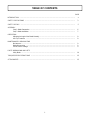
TABLE OF CONTENTS
INTRODUCTION ................................................................................................................................................... 2
SAFETY PRECAUTIONS ..................................................................................................................................... 3
SAFETY DECALS ................................................................................................................................................. 5
ASSEMBLY
Step 1: Blade Preparation ....................................................................................................................... 6
Step 2: Blade Installation ......................................................................................................................... 7
OPERATION
Adjusting the Angle of the Blade Manually ............................................................................................. 8
Anti-Trip Protection .................................................................................................................................. 8
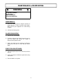
MAINTENANCE & DISMOUNTING
Maintenance ............................................................................................................................................. 9
Blade Dismounting ................................................................................................................................... 9
End of Season Storage ........................................................................................................................... 9
PARTS BREAKDOWN AND LISTS
Utility Blade ............................................................................................................................................... 10
TORQUE SPECIFICATION TABLE ..................................................................................................................... 12
ATTACHMENTS .................................................................................................................................................... 13
PAGE

2
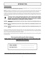
INTRODUCTION
TO THE PURCHASER
This new attachment was carefully designed to give years of dependable service. This manual has been provided to
assist in the safe operation and servicing of your attachment.
NOTE: All photographs and illustrations in the manual may not necessarily depict the actual models or attachment, but
are intended for reference only and are based on the latest product information available at the time of publication.
Familiarize yourself fully with the safety recommendations and operating procedures before putting the machine to use.
Carefully read, understand and follow these recommendations and insist that they be followed by those who will use
this attachment.
THIS SAFETY ALERT SYMBOL IDENTIFIES AN IMPORTANT SAFETY MESSAGE IN THIS MANUAL
THAT HELPS YOU AND OTHERS AVOID PERSONAL INJURY OR EVEN DEATH. DANGER,
WARNING, AND CAUTION ARE SIGNAL WORDS USED TO IDENTIFY THE LEVEL OF HAZARD.
HOWEVER, REGARDLESS OF THE HAZARD, BE EXTREMELY CAREFUL.
DANGER: Signals an extreme hazard that will cause serious injury or death if recommended precautions are
not followed.
WARNING: Signals a hazard that may cause serious injury or death if the recommended precautions are not
followed.
CAUTION: Signals a hazard that may cause minor or moderate injury if the recommended precautions are not
followed.
Record your attachment serial number and purchase date in the section reserved below (there is no serial number on
the subframe). Your dealer requires this information to give you prompt, efficient service when ordering replacement
parts. Use only genuine parts when replacements are required.
If warranty repairs are required please present this registration booklet and original sales invoice to your selling dealer
for warranty service.
This manual should be kept for future reference.
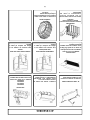
Please check if you have received all the parts for your kit with the list of the
bag and the list of the box.
7
SERIAL NUMBER : ___________________________
PURCHASE DATE : ___________________________
In this manual, right and left sides are determined by sitting on the tractor seat facing forward.

3
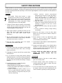
SAFETY PRECAUTIONS
TRAINING
This symbol, "Safety Alert Symbol", is used
throughout this manual and on the utility blade
safety labels to warn of the possibility of serious
injury. Please take special care in reading and
understanding the safety precautions before
operating the tractor or the utility blade .
1. Read this Owner's Manual carefully. Be thoroughly
familiar with the controls and proper use of the
tractor and utility blade. Know how to stop the unit
and disengage the controls quickly.
2. Never allow children to operate the tractor nor the
utility blade. Never allow adults to operate the
tractor nor the utility blade without proper
instructions.
3. No one should operate the tractor nor the utility
blade while intoxicated or while taking medication
that impairs the senses or reactions.
4. Keep the area of operation clear of all people,
particularly small children and pets.
PREPARATION
1. Thoroughly inspect the area where the utility blade
is to be used and remove door mats, all foreign
objects and the like.
2. Disengage all clutches and shift into neutral before
starting engine.
3. Do not operate the utility blade without wearing
adequate garments. Avoid loose fitting clothing that
can get caught in moving parts. Wear footwear that
will protect you feet and improve footing on slippery
surfaces.
4. Handle fuel with care, it is highly flammable.
a) Use approved fuel container.
b) Never add fuel to a running engine or hot engine.
c) Fill fuel tank outdoors with extreme care. Never fill
fuel tank indoors.
d) Never fill containers inside a vehicle, or on a
truck or a trailer bed with a plastic liner. Always
place containers on the ground, away from your
vehicle, before filling.
Careful operation is your best insurance against an accident. Read this section carefully before operating the tractor
and attachment. All operators, no matter how experienced they may be, should read this and other manuals related to
the tractor and utility blade before operating. It is the owner's legal obligation to instruct all operators in safe operation of
the utility blade
.
7
e) When practical, remove gas-powered
equipment from the truck or trailer and refuel it
on the ground. If this is not possible, then
refuel such equipment on a trailer with a
portable container, rather than from a gasoline
dispenser nozzle.
f) Keep the nozzle in contact with the rim of the
fuel tank or container opening at all times, until
refuelling is complete. Do not use a nozzle
lock-open device.
g) Replace fuel cap securely and wipe up spilled
fuel.
h) If fuel is spilled on clothing, change clothing
immediately.
5. Adjust the skid shoes so that the utility blade
doesn’t sink into the gravel or doesn’t scrape the
paving stones.
6. Never attempt to make any adjustments while
engine is running (except where specifically
recommended by manufacturer).
7. Let the tractor’s engine adjust to outside temperature
before pushing the snow.
8. Always wear safety glasses or eye shields during
operation or while performing an adjustment or
repairs to protect eyes from foreign objects that
may be thrown from the machine.
9. Never modify the utility blade or any part
without the written consent from the
manufacturer.
OPERATION
1. Do not put hands or feet near or under rotating
parts nor the utility blade.
2. Exercise extreme caution when operating on or
crossing gravel drives, walks, or roads. Stay alert
for hidden hazards or traffic.
3. If the unit should start to vibrate abnormally, stop
the engine (motor) and check immediately for the
cause. Vibration is generally a warning of trouble.

4
SAFETY PRECAUTIONS
MAINTENANCE AND STORAGE
1. Check mounting bolts and other bolts at frequent
intervals for proper tightness to be sure they are tight
the utility blade is in safe working condition.
2. Never store the tractor with fuel in the tank inside a
building where ignition sources are present, such as
hot water tanks, space heaters, clothes dryers and
the like. Allow engine to cool before storing in any
enclosure.
3. Maintain or replace safety and instructions labels, as
necessary.
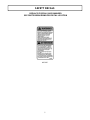
WHENEVER YOU SEE THIS SYMBOL
7
IT MEANS:
WARNING!
BECOME ALERT !
YOUR SAFETY IS INVOLVED!
7
WARNING
7
FOR YOUR SECURITY:
Read the subframe owner's manual for safety
precautions and rules.
Follow the assembly and operation instructions.
4. Stop the engine (motor) whenever you leave the
operating position and when making repairs,
adjustments or inspections.
5. Do not run engine indoors except when starting
engine and transporting attachment, in or out of
building. Do not operate or let motor run in a
storage area without ventilation because gas
contains carbon monoxide which is odourless,
colourless and can cause death.
6. Take all possible precautions when leaving the
machine unattended. Lower the utility blade, shift
into neutral, set the parking brake, stop the
engine and remove the key. Wait for all moving
parts to stop.
7. Never use the utility blade across the face of
steep slopes. Exercise extreme caution when
changing directions on slopes.
8. Do not tolerate anyone, nor children or domestic
animals in the operating zone.
9. Do not carry passengers on the utility blade or the
tractor.
10. Use only tire chains approved by the
manufacturer when you clear snow.
11. Use only accessories approved by the
manufacturer of the utility blade (such as wheel
chains, counterweights, cabs). You must use 100
lbs. of rear counterweight for better traction and a
greater stability at all times when using a utility
blade that is installed on the front of a tractor.
12. Never operate the utility blade without good
visibility or light.
Page is loading ...

6
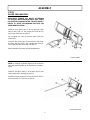
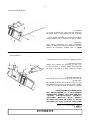
ASSEMBLY
Install the push frame (item 1) to the attaching frame
(item 2) with a 5/8 x 4’’ hex socket cap screw (item 3)
and a nylon insert lock nut (item 4).
Do not tighten too much so that the push frame can
rotate freely.
Install the skid shoes (item 5) to the back of the blade,
as shown with four 5/16 x 3/4” carriage bolts (item 6).
Secure the bolts with four flange nuts (item 7).
After installation see section skid shoe adjustment.
NOTE: If installing a hydraulic angling kit, do not do this
step and install according to the instructions included in
the kit.
Install the joint block (item 1) on the latch (item 2) and
hold in place with a retaining ring (item 3).
Install the control rod (item 5) on the joint block (item 1)
and secure with a 2.5 mm hair pin (item 4).
IMPORTANT: TORQUE ALL BOLTS ACCORDING
TO TORQUE SPECIFICATION TABLE (SEE TABLE
OF CONTENTS) WHEN STATED: TIGHTEN FIRMLY.
REFER TO PARTS BREAKDOWN SECTION FOR
THEIR IDENTIFICATION.
STEP 1
BLADE PREPARATION:
Prepare blade
Install control rod

7
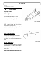
ASSEMBLY
Attach the blade to the subframe as shown.
Make sure the blade’s push frame is pushed in until
locked into place by the springs (item 1).
NOTE: If the blade is equipped with a hydraulic
angling kit, do not do this step and connect the
hydraulic hose to the tractor’s valve.
Install the handgrip (item 1) on the handle (item 2) and
slide the handle in handle support (item 3).
Install the handle on the control rod (item 4).
Secure with the hair pin (item 5).
VERIFY TIRE PRESSURE:
Check and adjust tractor tire pressure as follows:
Front tires: 14-15 psi
Back tires: 7-8 psi
Tire pressure must be even on both sides of the
tractor.
ADJUST SKID SHOES:
On a level surface, raise the blade off the ground and
insert some shims to the desired height under the
blade. Lower the blade on the shims. Loosen the
bolts that hold the skid shoes and slide them down to
the ground in order to get the desired height. Tighten
the nuts firmly.
NOTE: The two skid shoes must be adjusted to the
same height.
STEP 2
BLADE INSTALLATION:
7
WARNING
7
TO PREVENT INJURIES:
Stop the motor.
Apply parking brake.
Remove the ignition key.
Attach the blade
Install handle

8
OPERATION
ADJUSTING THE ANGLE OF THE BLADE
MANUALLY:
To adjust the angle, turn the handle counter-clockwise
to unlock the latch. Push or pull the handle to adjust the
blade to the desired angle.
ANTI-TRIP LOCK PROTECTION:
The blade was designed to topple forward when striking
solid objects. Once the blade clears the obstacle, it will
spring back to its normal operating position, therefore,
protecting the operator and tractor from any impacts that
might occur.
DO NOT USE ANTI-TRIP LOCKS WHEN
PERFORMING LIGHT JOBS AT HIGH SPEEDS
MORE THAN 2MPH OR 3KM/H.
7
WARNING
7
Read the tractor Owner’s manual carefully. Be
thoroughly familiar with the controls & proper
use of the attachment.
7
WARNING
7
TO PREVENT INJURIES AND FOR MORE
TRACTION WHEN USING THE ATTACHMENT:
-Rear counterweight of 150 lbs. minimum is
required to counterbalance attachment’s weight.
-Tractor manufacturer approved tire chains are
required.
-Do not operate on a slope greater than 10°.
-When dismounting the attachment remove rear
counterweights.

9
MAINTENANCE & DISMOUNTING
MAINTENANCE:
a) Verify the mounting bolts at frequent intervals for
proper tightness in order to prevent costly repairs.
Make sure that your equipment is in safe working
condition.
b) Lubricate all pivoting points.
BLADE DISMOUNTING:
a) Remove rear counterweights.
b) Straighten and lower the blade. Remove the hair pin
from the handle and remove the handle or
disconnect the hydraulic hoses.
c) Detach the blade from the subframe by lifting the
spring locks one side at a time and pull out the
blade.
END OF SEASON STORAGE:
a) Clean and repaint all parts from which the paint has
worn off.
b) Inspect and replace all defective parts before using
next season.
c) Store the blade in a dry place.
7
WARNING
7
TO PREVENT INJURIES:
Stop the motor.
Apply parking brake.
Remove the ignition key.
Page is loading ...

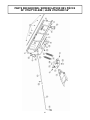
11
Ref.
Réf.
English description Description française
Qty.
Qté.
Part #
Pièce #
1 Blade Lame 1 104326
2 Cutting edge 56" Racloir 56" 1 104325
3 Carriage bolt 5/16" n.c. x 3/4" Boulon à carrosserie 5/16" n.c. x 3/4" 4 O/L
4 Flange nut 5/16" n.c. Écrou à bride 5/16" n.c. 10 O/L
5 Hex. bolt 1/2" n.c. x 2" Boulon hex. 1/2" n.c. x 2" 2 O/L
6 Flat washer 9/16" hole Rondelle plate 9/16" trou 2 O/L
7 Bushing Coussinet 2 103489
8 Lock washer 1/2" Rondelle de blocage 1/2" 2 O/L
9 Nylon Insert lock Nut 1/2" n.c. Écrou à garniture de nylon 1/2" n.c. 2 O/L
10 Nylon insert lock nut 5/8" n.c. Écrou à garniture de nylon 5/8" n.c. 1 O/L
11 Push frame Châssis de poussée 1 103488
12 Spring Ressort 2 102918
13 Attaching frame Châssis d'attache 1 103501
14 Handle Poignée 1 103492
15 Handgrip Poignée 1 102062
16 Skid shoe Patin 2 103496
17 Latch Loquet 1 103495
18 Joint block Bloc de joint 1 102275
19 Retaining ring Bague de retenue 1 102378
20 Hair pin 2.5mm Goupille à ressort 2.5mm 1 102013
21 Control rod Tige de contrôle 1 103498
22 Spring Ressort 1 103494
23 Carriage bolt 5/16" n.c. x 1" Boulon à carrosserie 5/16" n.c. x 1" 6 O/L
24 Hex. socket cap screw 5/8'' n.c. x 4'' Vis à tête cylindrique hex. 5/8'' n.c. x 4'' 1 O/L
25 Hair pin 3mm Goupille à ressort 3mm 1 102617
26 Warning decal Décalque attention 1 103165
27 Berco decal Décalque Berco 1 102471
28 Serial number Numéro de série 1 REF
29 Hex. bolt 5/16" n.c. x 1 1/4" Boulon hex. 5/16" n.c. x 1 1/4" 1 O/L
30 Hex. nut 5/16" n.c. Écrou hex. 5/16" n.c. 1 O/L
PARTS LIST / LISTE DES PIÈCES
O/L = Obtain locally/obtenir localement

12
GENERAL TORQUE SPECIFICATION TABLE
USE THE FOLLOWING TORQUES WHEN SPECIAL TORQUES ARE NOT GIVEN
NOTE: These values apply to fasteners as received from supplier, dry or when lubricated with normal oil. They do not apply if
special graphited or moly disulphide greases or other extreme pressure lubricants are used. This applies to both UNF and UNC
threads.
TORQUE SPECIFICATION TABLE
SEE Grade No.
2 5 8 *
BOLT HEAD
IDENTIFICATION
MARKS AS PER GRADE
NOTE MANUFACTURING
MARKS WILL VARY
TORQUE TORQUE TORQUE
BOLT SIZE POUNDS FEET NEWTON-METERS POUNDS FEET NEWTON-METERS POUNDS FEET NEWTON-METERS
Inches Millimetre Min. Max. Min. Max. Min. Max. Min. Max. Min. Max. Max. Min. Max. Max.
1/4" 6.35 5 6 6.8 8.13 9 11 12.2 14.9 12 15 16.3 30.3
5/16" 7.94 10 12 13.6 16.3 17 20.5 23.1 27.8 24 29 32.5 39.3
3/8" 9.53 20 23 27.1 31.2 35 42 47.5 57 45 54 61 73.2
7/16" 11.11 30 35 40.7 47.4 54 64 73.2 86.8 70 84 94.9 113.9
1/2" 12.7 45 52 61 70.5 80 96 108.5 130.2 110 132 149.2 179
9/16" 14.29 65 75 88.1 101.6 110 132 149.2 179 160 192 217 260.4
5/8" 15.88 95 105 128.7 142.3 150 180 203.4 244.1 220 264 298.3 358
3/4" 19.05 150 185 203.3 250.7 270 324 366.1 439.3 380 456 515.3 618.3
7/8" 22.23 160 200 216.8 271 400 480 542.4 650.9 600 720 813.6 976.3
1" 25.4 250 300 338.8 406.5 580 696 786.5 943.8 900 1080 1220.4 1464.5
*Thick nuts must be used with grade 8 bolts
METRIC BOLT TORQUE SPECIFICATIONS
COARSE THREAD
Size Screw Grade No. Pitch (mm) Pounds Feet Newton-Meters Pitch (mm) Pounds Feet Newton-Meters
M6 4T 1.00 3.6 - 5.8 4.9 - 7.9 - - -
7T
5.8 - 9.4 7.9 - 12.7
- -
8T
7.2 - 10 9.8 - 13.6
- -
M8 4T 1.25 7.2 - 14 9.8 - 19 1.00 12 - 17 16.3 - 23
7T
17 - 22 23 - 29.8
19 - 27 25.7 - 36.6
8T
20 - 26 27.1 - 35.2
22 - 31 29.8 - 42
M10 4T 1.50 20 - 25 27.1 - 33.9 1.25 20 - 29 27.1 - 39.3
7T
34 - 40 46.1 - 54.2
35 - 47 47.4 - 63.7
8T
38 - 46 51.5 - 62.3
40 - 52 54.2 - 70.5
M12 4T 1.75 28 - 34 37.9 - 46.1 1.25 31 - 41 42 - 55.6
7T
51 - 59 69.1 - 79.9
56 - 68 75.9 - 92.1
8T
57 - 66 77.2 - 89.4
62 - 75 84 - 101.6
M14 4T 2.00 49 - 56 66.4 - 75.9 1.50 52 - 64 70.5 - 86.7
7T
81 - 93 109.8 - 126
90 - 106 122 - 143.6
8T
96 - 109 130.1 - 147.7
107 - 124 145 - 168
M16 4T 2.00 67 - 77 90.8 - 104.3 1.50 69 - 83 93.5 - 112.5
7T
116 - 130 157.2 - 176.2
120 - 138 162.6 - 187
8T
129 - 145 174.8 - 196.5
140 - 158 189.7 - 214.1
M18 4T 2.00 88 - 100 119.2 - 136 1.50 100 - 117 136 - 158.5
7T
150 - 168 203.3 - 227.6
177 - 199 239.8 - 269.6
8T
175 - 194 237.1 - 262.9
202 - 231 273.7 - 313
M20 4T 2.50 108 - 130 146.3 - 176.2 1.50 132 - 150 178.9 - 203.3
7T
186 - 205 252 - 277.8
206 - 242 279.1 - 327.9
8T
213 - 249 288.6 - 337.4
246 - 289 333.3 - 391.6
FINE THREAD

13
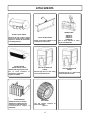
ATTACHMENTS
ROTARY BROOM
#700380 with nylon brush
/#700381 with polypropylene brush.
Fits on same subframe as
snowblower & utility blade.
Requires an adaptor.
UTILITY BLADE #700266
Mounts on the same subframe as the
snowblower & rotary broom.
COUNTERWEIGHT
#700240 Universal rear weights
#700246 Rear weights Electrolux
Required for safety and traction.
Counterbalances weight of
attachment.
TRACTOR WINTER CAB
#700271
Universal type fits on a wide variety
of lawn and garden tractors.
ROTARY TILLER #700312
Mounts to the rear of lawn & garden
tractors 14 to 25 HP. Comes complete
with drive & manual lift mechanisms
& mounting hardware.
TRACTOR SCREEN CAB
#700313
Universal type fits on a wide variety
of lawn and garden tractors.
SNOWBLOWER
#700210 40"
#700211 44"
#700255 40’’
#700400 48’’
Fits on same subframe as rotary
broom and utility blade.
TIRE CHAINS
Two link spacing. Required for
traction and safety.
Pkg. of 2
Page is loading ...
Page is loading ...
Page is loading ...
Page is loading ...
Page is loading ...
Page is loading ...
Page is loading ...
Page is loading ...
Page is loading ...
Page is loading ...
Page is loading ...
Page is loading ...

1
MANUEL DU PROPRIÉTAIRE
Modèle Numéro
BERCO
Lame utilitaire 56"
pour
TRACTEURS DE JARDIN
ATTENTION:
LIRE & SUIVRE TOUTES LES RÈGLES DE SÉCURITÉ & INSTRUCTIONS
AVANT D’UTILISER CET ÉQUIPEMENT
104327
G-05
700416
* ASSEMBLAGE * PIÈCES DE RÉPARATION
* OPÉRATION * ENTRETIEN
-
 1
1
-
 2
2
-
 3
3
-
 4
4
-
 5
5
-
 6
6
-
 7
7
-
 8
8
-
 9
9
-
 10
10
-
 11
11
-
 12
12
-
 13
13
-
 14
14
-
 15
15
-
 16
16
-
 17
17
-
 18
18
-
 19
19
-
 20
20
-
 21
21
-
 22
22
-
 23
23
-
 24
24
-
 25
25
-
 26
26
-
 27
27
-
 28
28


Ask a question and I''ll find the answer in the document
Finding information in a document is now easier with AI
in other languages
Related papers
-
Bercomac 700266-2 User manual
-
-
-
-
-
-
-
-
-
Other documents
-
 Berco 700528-1 Owner's manual
-
 Renaissance Fireplaces RUMFORD 1500 Owner's manual
-
EGO RBA2100 Owner's manual
-
Wallenstein 3611A800 Installation guide
-
Walker 5600-20 User manual
-
A.O. Smith 100333536 Installation guide
-
Monosem SUPER-CROP Owner's manual
-
 John Deere SB1280 User manual
-
 John Deere SB1148 User manual
-
Frontier SB1174 User manual


