
(English)
DM-RD0001-06
Dealer's Manual
MTB Rear Derailleur
MTB SHADOW RD+
RD-M986
RD-M820
RD-M786
RD-M675
RD-M640
RD-M615
MTB SHADOW RD
RD-M981
RD-M781
RD-M670
RD-M610
RD-M4000
RD-M3000

2
CONTENTS
IMPORTANT NOTICE .............................................................................................. 3
TO ENSURE SAFETY ............................................................................................... 4
INSTALLATION ....................................................................................................... 6
Direct mount .......................................................................................................................6
Replacing with direct mount type .....................................................................................7
Mode converter (RD-M820) ................................................................................................8
ADJUSTMENT ........................................................................................................ 9
How to use the end adjust bolt (SHADOW RD+) ..............................................................9
SIS Adjustment (SHADOW RD+) .......................................................................................11
MAINTENANCE .................................................................................................... 12
Replacing the bump stopper/holder (RD-M820) .............................................................12
Replacing the plate and the plate tension spring (RD-M986) ........................................ 14
Replacing the plate and the plate tension spring (except RD-M986) ............................ 17
Replacing the B tension spring (RD-M4000 / RD-M3000) ...............................................20
Friction adjustment (RD-M986) ........................................................................................21
Friction adjustment (except RD-M986) ............................................................................23
Applying grease to the chain stabilizer ...........................................................................25
Replacing the pulley .........................................................................................................26

3
IMPORTANT NOTICE
•
This dealer’s manual is intended primarily for use by professional bicycle mechanics.
Users who are not professionally trained for bicycle assembly should not attempt to install the components themselves using the
dealer’s manuals.
If any part of the information on the manual is unclear to you, do not proceed with the installation. Instead, contact your place
of purchase or a local bicycle dealer for their assistance.
•
Make sure to read all instruction manuals included with the product.
•
Do not disassemble or modify the product other than as stated in the information contained in this dealer’s manual.
•
All dealer’s manuals and instruction manuals can be viewed on-line on our website (http://si.shimano.com).
•
Please observe the appropriate rules and regulations of the country, state or region in which you conduct your business as a
dealer.
For safety, be sure to read this dealer's manual thoroughly before use, and follow it for correct use.
The following instructions must be observed at all times in order to prevent personal injury and physical damage to
equipment and surroundings.
The instructions are classified according to the degree of danger or damage which may occur if the product is used
incorrectly.
DANGER
Failure to follow the instructions will result in death or serious injury.
WARNING
Failure to follow the instructions could result in death or serious injury.
CAUTION
Failure to follow the instructions could cause personal injury or physical damage to equipment and surroundings.

4
TO ENSURE SAFETY
WARNING
•
When installing components, be sure to follow the instructions that are given in the instruction manuals.
It is recommended that you use only genuine Shimano parts. If parts such as bolts and nuts become loose or damaged, the bicycle
may suddenly fall over, which may cause serious injury.
In addition, if adjustments are not carried out correctly, problems may occur, and the bicycle may suddenly fall over, which may
cause serious injury.
•
Be sure to wear safety glasses or goggles to protect your eyes while performing maintenance tasks such as replacing parts.
•
After reading the dealer’s manual thoroughly, keep it in a safe place for later reference.
Be sure to also inform users of the following:
•
Maintenance interval depends on the usage and riding circumstances. Clean regularly the chain with an
appropriate chain cleaner. Never use alkali based or acid based solvents such as rust cleaners. If those solvent be
used chain might break and cause serious injury.
•
Check the chain for any damage (deformation or crack), skipping, or other abnormalities such as unintended gear shifting. If
any problems are found, consult a dealer or an agency. The chain may break, and you may fall.
CAUTION
For Installation to the Bicycle, and Maintenance:
•
When installing and removing the plate and the plate unit, be careful to avoid injury such as getting your fingers caught by
the strong reaction force of the plate tension spring.
NOTE
Be sure to also inform users of the following:
•
When installing the SHADOW RD+, be sure to install the plate unit cover before riding the bicycle.
•
If gear shifting operations cannot be carried out smoothly, clean the derailleur and lubricate all moving parts.
•
If the amount of looseness in the links is so great that adjustment is not possible, you should replace the derailleur.
•
Products are not guaranteed against natural wear and deterioration from normal use and aging.
•
For maximum performance we highly recommend Shimano lubricants and maintenance products.

5
For Installation to the Bicycle, and Maintenance:
•
Depending on the shape of the frame, the rear derailleur may interfere with the chain stay.
•
Because the high cable resistance of a frame with internal cable routing would impair the SIS function, this type of frame
should not be used.
•
Grease the inner cable and the inside of the outer casing before use to ensure that they slide properly.
•
Do not let dust adhere on the inner cable. If the grease on the inner cable is wiped off, the application of SIS SP41 grease
(Y04180000) is recommended. Do not use premium grease or other types of grease, otherwise they may cause deterioration in
gear shifting performance.
•
For smooth operation, use the specified outer casing and the bottom bracket cable guide.
•
Use an outer casing which still has some length to spare even when the handlebars are turned all the way to both sides.
Furthermore, check that the shifting lever does not touch the bicycle frame when the handlebars are turned all the way.
•
If gear shifting adjustment cannot be carried out, check the degree of parallelism at the rear end of the bicycle. Also check if
the cable is lubricated and if the outer casing is too long or too short.
•
You should periodically clean the derailleur and lubricate all moving parts (mechanism and pulleys).
•
Depending on the model, the guide pulley has arrows on it to indicate the direction of rotation. Install the guide pulley so that
the arrows are pointing counterclockwise when looking at the outer side of the derailleur.
•
The tension pulley has an arrow on it to indicate the direction of rotation. Install the tension pulley so that the arrow is
pointing clockwise when looking at the outer side of the derailleur.
•
If you hear abnormal noise as a result of looseness in a pulley, you should replace the pulley.
The actual product may differ from the illustration because this manual is intended chiefly to explain the procedures for using
the product.

6
INSTALLATION
List of tools to be used
The following tools are needed to assemble this product.
Where to use Tool
Bracket axle 5 mm hexagon wrench
Mode converter 2 mm hexagon wrench (RD-M820)
End adjust bolt
Screwdriver[#2]
3 mm hexagon wrench (RD-M820)
Bump stopper
3 mm hexagon wrench
1.5 mm hexagon wrench
Plate stopper pin Screwdriver[#2]
Plate unit cover bolt 2 mm hexagon wrench
Plate axle 4 mm hexagon wrench
Friction adjustment bolt 5.5 mm wrench
Guide pulley/Tension pulley 3 mm hexagon wrench
Top/Low adjustment screw Screwdriver[#2]
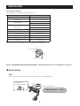
Move the lever switch to the OFF position before installing the SHADOW RD+.
Lever switch
ON
OFF
Refer to "REAR DERAILLEUR FOR MTB/TREKKING" in the General Operations for installation to the frame.
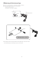
Direct mount
Note:
Direct mount rear derailleurs can only be mounted on direct-mount compatible frames.
The E-ring is not
necessary for installation.
5 mm hexagon wrench
Tightening torque: 8 - 10 N·m

7
Replacing with direct mount type
1.
If there is an E-ring attached, use a flat-head screwdriver to remove it.
2.
Using a 5 mm hexagon wrench, remove the bracket axle.
•
If there is a spacer, remove it.
•
The E-ring is not necessary for installation.
E-ring
5 mm hexagon wrench
1
2
Bracket
Spacer
Tightening torque: 8 - 10 N·m
When replacing the direct mount type with the bracket-equipped type, reverse the procedure.
•
For models with a spacer, insert the spacer into the correct position.

8
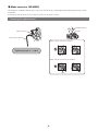
Mode converter (RD-M820)
This derailleur is compatible with two types of sprockets: Freeride mode (11-32T/11-34T/11-36T) and downhill mode (11-23T/12-
25T/11-28T).
If using the freeride mode sprockets, you will also need to use the mode converter.
Removing the mode converter
Mode converter
2 mm hexagon wrench
Tightening torque: 1 - 1.5 N·m
When a mode converter is installed
When a mode converter is not installed
Bracket
Derailleur hanger

9
ADJUSTMENT
This section describes the adjustment procedure for the SHADOW RD+.
Refer to ”Rear derailleur” in the General Operations for items not explained in this section.
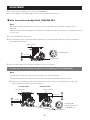
How to use the end adjust bolt (SHADOW RD+)
Note:
Move the lever switch to the OFF position to reduce the tension of the plate tension spring before carrying out this
adjustment.
If the lever switch remains at the ON position so that the screw is difficult to turn, the screw may become damaged if you try to
force it to turn.
1.
Set the rear derailleur to the low gear.
2.
After stopping the wheel, check that the distance between the tip of the guide pulley and the tip of the gear is within the
range shown in the illustration.
1
2
Largest sprocket
5 - 6 mm
•
Screwdriver[#2]
End adjust bolt
3.
Turn the crank to shift gears to check that other gears do not have a rough feel.
Checking the distance between the sprocket and the guide pulley (RD-M820/M640)
Note:
If the number of teeth for the cassette sprocket is changed, carry out this setting again.
1.
Set the rear derailleur to the largest (at freeride mode) or the smallest (at downhill mode) gear position.
2.
Stop the wheel from turning, and then check that the distance from the edge of the guide pulley to the edge of the
sprocket is within the range as shown in the illustration.
1
2
•
Screwdriver[#2]
•
3 mm hexagon wrench
for RD-M820 only
End adjust bolt
Freeride mode
Largest sprocket
Smallest sprocket
5 - 6 mm
Downhill mode
1
2
10 - 11 mm

10
3.
If the frame interferes with the rear derailleur on models with a bump stopper when the plate unit is lifted up, turn the end
adjust bolt until there is no interference.
Load:
approx. 49 - 78.4 N
The frame and the rear derailleur should not interfere.
4.
Turn the crank arm to shift gears and check that there is no roughness in the feel.
Note: RD-M640 About freeride specification/downhill specification
RD-M640 differs between freeride specification and downhill specification.
The specification cannot be changed by replacing the bracket only.
A mode converter is not equipped, either.
Downhill specification
Freeride specification

11
SIS Adjustment (SHADOW RD+)
1.
Set the lever switch to OFF.
2.
Operate the shifting lever once to move the chain to the 2nd sprocket.
3.
Then, while pressing the lever just enough to take up the play in the lever, turn the crank arm.
•
The best setting is when the shifting lever is operated just enough to take up the gap and the
chain touches the 3rd sprocket and makes noise.
•
The best setting is when the shifting lever is operated just enough to take up the gap and the
chain touches the 3rd sprocket and makes noise.
•
When shifting to 3rd
Tighten the outer casing adjustment barrel until the chain returns to the 2nd sprocket. (clockwise)
Outer casing adjustment barrel
•
When no sound at all is heard
Loosen the outer casing adjustment barrel until the chain touches the 3rd sprocket and makes noise. (counterclockwise)
Outer casing adjustment barrel
4.
Return the lever to its original position (the position where the lever is at the 2nd sprocket setting and it has been released)
and then turn the crank arm clockwise.
•
If the chain is touching the 3rd sprocket and making noise, turn the outer casing adjustment barrel clockwise slightly to
tighten it until the noise stops and the chain runs smoothly.
5.
Operate lever to change gears, and check that no noise occurs in any of the gear positions.
6.
Set the lever switch to ON, and then ride the bicycle normally and check that there are no problems with gear shifting.
7.
For the best SIS performance, periodically lubricate all power-transmission parts.

12
MAINTENANCE
Replacing the bump stopper/holder (RD-M820)
Note: Remove the rear derailleur from the frame before replacement.
1.
Using a flat-head screwdriver, remove the E-ring.
2.
Remove the bracket axle with a 5 mm hexagon wrench and remove the bracket.
•
If there is a spacer, remove it.
E-ring
5 mm hexagon wrench
1
2
Bracket
Tightening torque: 8 - 10 N·m

13
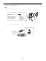
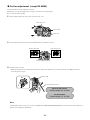
3.
Using a 3 mm hexagon wrench, remove the end adjust bolt.
4.
Using a 3 mm hexagon wrench, push the bottom of the bump stopper to remove it.
Push a 3 mm hexagon wrench
into the screw hole.
Bump stopper
4
End adjust bolt
3
4
Push
3 mm hexagon wrench
Bump stopper
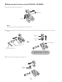
5.
Push in the bump stopper with a 1.5 mm hexagon wrench in the low state as shown in the illustration.
1.5 mm hexagon wrench

14
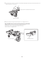
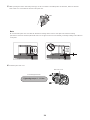
6.
Remove the bump stopper holder with a narrow-tipped tool.
Bump stopper holder
* Reassemble by carrying out the removal procedure in reverse.
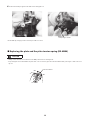
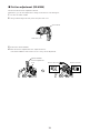
Replacing the plate and the plate tension spring (RD-M986)
CAUTION
•
Always ensure that the lever switch is in the OFF position before starting work.
•
If operating the lever switch while the plate unit cover is removed, press the switch stabilizer with your finger so that it does not
fly out.
ON
Switch stabilizer
OFF

15
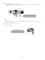
Removing the plate and the plate tension spring
1.
Remove the plate stopper pin.
Plate stopper pin
Screwdriver[#2]
Tightening torque: 1 N·m
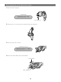
2.
Turn the plate to loosen the plate tension spring as shown in the illustration.
3.
Remove the plate unit cover bolts.
2 mm hexagon wrench
Tightening torque: 1 - 1.5 N·m
4.
Remove the switch stabilizer and the chain stabilizer.
Switch stabilizer
Chain stabilizer

16
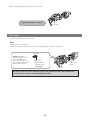
5.
Use a 4 mm hexagon wrench to remove the plate axle.
Plate axle
Tightening torque: 8 - 10 N·m
Reassembly
Carry out the removal procedure in reverse.
Note:
•
Apply grease to the plate axle.
•
When reassembling, insert the end of the plate tension spring into the groove in the plate.
DO NOT apply grease.
If the outer surface of the
roller clutch with non
groove part gets grease on
it, it will slip and the friction
function will not work.
Apply grease.
•
Grease number:
premium grease
(Y04110000)
Plate axle
Be sure to install the switch stabilizer. If you try to operate the lever switch without the
switch stabilizer installed, it will damaged the product.
Plate tension
spring
Plate axle

17
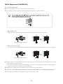
Replacing the plate and the plate tension spring (except RD-M986)
CAUTION
•
Always ensure that the lever switch is in the OFF position before starting work.
•
If operating the lever switch while the plate unit cover is removed, press the friction unit with your finger so that it does not fly
out.
ON
Friction unit
OFF
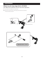
Removing the plate and the plate tension spring
1.
Remove the plate stopper pin.
Plate stopper pin
Screwdriver[#2]
Tightening torque: 1 N·m
2.
Turn the plate to loosen the plate tension spring as shown in the illustration.
Note:
Steps 1 and 2 do not apply to RD-M4000 / RD-M3000.

18
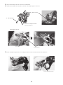
3.
Remove the plate unit cover bolts.
2 mm hexagon wrench
Tightening torque: 1 - 1.5 N·m
Plate unit cover bolt
4.
Remove the cam unit and the chain stabilizer.
Cam unit
Chain stabilizer
5.
Use a 4 mm hexagon wrench to remove the plate axle.
Plate axle
Tightening torque: 8 - 10 N·m

19
Reassembly
Carry out the removal procedure in reverse.
Note:
•
Apply grease to the plate axle.
•
When reassembling, insert the end of the plate tension spring into the groove in the plate.
Plate tension
spring
DO NOT apply grease.
If the outer surface of the
roller clutch with non
groove part gets grease on
it, it will slip and the friction
function will not work.
Apply grease.
•
Grease number:
premium grease
(Y04110000)
Plate axle
•
Set the cam unit as shown in the illustration.
Set with the
projection facing
down.
Set with the uneven side
to the right.

20
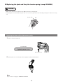
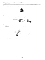
Replacing the B tension spring (RD-M4000 / RD-M3000)
1.
Remove the E-ring from the bracket axle.
E-ring
Bracket axle
Note:
Some models do not have an E-ring. (Function is not affected.)
2.
Remove the bracket axle using a 5 mm hexagon wrench, then remove the B tension spring and adapter set from the bracket
member.
Tightening torque: 8 - 10 N·m
Adapter set
Bracket member
B tension
spring
5 mm hexagon wrench
Bracket axle
B axle bush
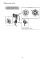
3.
Remove the B tension spring from the adapter set.
B tension
spring
Page is loading ...
Page is loading ...
Page is loading ...
Page is loading ...
Page is loading ...
Page is loading ...
Page is loading ...
-
 1
1
-
 2
2
-
 3
3
-
 4
4
-
 5
5
-
 6
6
-
 7
7
-
 8
8
-
 9
9
-
 10
10
-
 11
11
-
 12
12
-
 13
13
-
 14
14
-
 15
15
-
 16
16
-
 17
17
-
 18
18
-
 19
19
-
 20
20
-
 21
21
-
 22
22
-
 23
23
-
 24
24
-
 25
25
-
 26
26
-
 27
27


Ask a question and I''ll find the answer in the document
Finding information in a document is now easier with AI
Related papers
-
Shimano RD-7401 Service Instructions
-
-
Shimano RD-M280 Dealer's Manual
-
Shimano RD-RX800 Dealer's Manual
-
Shimano RD-9070 User manual
-
Shimano FD-M676 Dealer's Manual
-
-
Shimano RD-6770-A Exploded View
-
Shimano RD-M5120 Dealer's Manual
-
Other documents
-
Apollo 2009 Owner's manual
-
Infinity Mountain Bicycle Owner's manual
-
 Stitch KM2002-1-JV Operating instructions
-
-
 Merida Sport User manual
-
-
Diamondback SHEPPARD CYCLES Owner's manual
-
 Avigo DUAL SUSPENSION MOUNTAIN BICYCLES User manual
-
Currier Tech Ezip Owner's manual
-
Grace Easy User manual


