Pulsar PSCU04344SEP Operating instructions

Category
Security device components
Type
Operating instructions

The Pulsar PSCU04344SEP is a reliable power supply unit designed to provide continuous power to 4 HD cameras, with a maximum current efficiency of 4A. It features 4 independent, galvanically isolated outputs, each protected by 1A fuses, ensuring stable operation and protection against short circuits or overloads. The unit operates on a supply voltage of 230V AC and delivers a constant voltage in the range of 30 to 35V DC, making it suitable for powering cameras with varying current requirements.

The Pulsar PSCU04344SEP is a reliable power supply unit designed to provide continuous power to 4 HD cameras, with a maximum current efficiency of 4A. It features 4 independent, galvanically isolated outputs, each protected by 1A fuses, ensuring stable operation and protection against short circuits or overloads. The unit operates on a supply voltage of 230V AC and delivers a constant voltage in the range of 30 to 35V DC, making it suitable for powering cameras with varying current requirements.

PSCU 04344SEP
v.1.1
PSCU 34VDC/4A/4x1A/SEP
Power supply for 4 HD cameras, 4A, for transmission lines
EN**
Edition: 5 from 08.01.2018
Supersedes the edition: 4 from 08.06.2017
www.pulsar.pl PSCU 04344SEP
2
PSU features:
DC 34V/4x1A unregulated power output
Supply voltage 230V AC
4 independent, galvanically isolated outputs
4 outputs independently protected by 1A fuses
LED optical indication
Protections:
Short-circuit protection SCP
overload protection OLP
transformer overheat protection OHP
surge protection
warranty 5 years from the production date
Example of application of the PSCU04344SEP power supply for 4 cameras, 4A for long lines.
4 x 1A / 34V DC
Schematic diagram of the PSCU04344SEP power supply application.
4 independently galvanically isolated outputs
www.pulsar.pl PSCU 04344SEP
3
TABLE OF CONTENTS:
1. Technical description.
1.1 General description
1.2 Block diagram
1.3 Description of components and connectors of the power supply
1.4 Technical parameters
2. Installation.
2.1 Requirements
2.2 Installation procedure
3. Optical indication.
4. Service and operation.
4.1 Overload or short-circuit of the power supply output
4.2 Maintenance
1. Technical description.
1.1 General description.
The PSCU04344SEP power supply is dedicated to solve the problem of long sections of cables (voltage
drops). The PSU supplies constant voltage in the range 30÷35V DC and current efficiency of I=4x1A, by a supply
line to the DCDC10H or DCDC15H converters. The choice of the converter is determined by the maximum current
consumption of the camera. The DCDC10H converter is designed to supply cameras with current consumption of
0,8A/12V DC max. For cameras with max current consumption of 1,2A/12V DC, DCDC15H converter is
recommended. The converters’ voltage is regulated to 12VDC, enabling power supply of the cameras. The PSU is
fitted with 4 independent, galvanically isolated outputs protected by melting fuses.
1.2 Block diagram (Fig.1).
Fig.1. Block diagram of the PSU.
1.3 Description of components and connectors of the power supply (Table.1, Fig. 2).
Table 1. Components of the LP4/SEP strip (see Fig. 2).
Element nr
Description
AC1÷AC4 AC power supply input from the transformer
F1÷F4 fuses in the AUX1...AUX4 output circuits
L1÷L4 LEDs indicating voltage at the individual outputs
AUX1÷AUX4 independently protected outputs
www.pulsar.pl PSCU 04344SEP
4
Fig. 2. The view of the LP4/SEP strip.
Tab.2 Components of the PSU (see Fig. 3).
Description
Isolation transformer
LP4/SEP rectifying strip
F
MAIN
fuse in the power supply circuit (230V AC)
L-N power supply connector 230V AC, protective connector PE
Table 2. Components of the PSU.
Fig.3. The view of the PSU.
1.4 Technical parameters:
- Electrical parameters (Table 3)
- Mechanical parameters (Table 4)
- Safety of use (Table 5)
- Operation parameters (Table 6)
www.pulsar.pl PSCU 04344SEP
5
Electrical parameters (Table 3)
Supply voltage
230V AC
Current consumption
0,8A@230V AC max.
PSU’s power
120W max.
Output voltage
3035V DC (100% load ÷ 0% load)
Output current
4x1A@30V DC max.
Short-circuit protection SCP
4x T 1A melting fuse (failure requires fuse replacement)
Overload protection OLP
DC 30V: 4 x T 1A circuit
AC 230V: T 3,15A circuit
Surge protection
varistors
Mechanical parameters (Table 4)
Dimensions
W=270, H=150, D+D
1
=72 +8 [+/- 2 mm]
W
1
=275, H
1
=154 [+/- 2 mm]
Mounting
see Fig. 3
Battery housing
2,7kg / 2,8kg
Net/gross weight
Steel plate, DC01 1,0mm color RAL 9003
Enclosure
Cylindrical screw x 2 (at the front)
Terminals
Mains supply: Φ0,63-2,50 (AWG 22-10)
Outputs: Φ0,51-2,05 (AWG 24-12)
Notes
The enclosure does not adjoin the mounting surface so that cables can be led.
Safety of use (Table 5)
Protection class PN-EN 60950-1:2007
I (first)
Protection grade PN-EN 60529: 2002 (U)
IP20
Insulation electrical strength:
- between input (network) circuit and the output circuits of the PSU (I/P-O/P)
- between input circuit and PE protection circuit (I/P-FG)
- between output circuit and PE protection circuit (O/P-FG)
3000 V/AC min.
1500 V/AC min.
500 V/AC min.
Insulation resistance:
- between input circuit and output or protection circuit
100 MΩ, 500V/DC
Operation parameters (Table 6)
Environmental class
II
Operating temperature
-10ºC...+40ºC
Storing temperature
-20ºC...+60ºC
Relative humidity
20%...90%, no condensation
Vibrations during operation
unacceptable
Surges during operation
unacceptable
Direct insolation
unacceptable
Vibrations and surges during transport
According to the PN-83/T-42106 standard
2. Installation.
2.1 Requirements.
The power supply unit should be mounted by a qualified installer, holding relevant permits and licenses
(applicable and required for a given country) for 230V/AC and low-voltage installations. The unit should be
mounted in confined spaces, in accordance with the 2nd environmental class, with normal relative humidity
(RH=90% maximum, no condensation) and temperature range from -10°C up to +40°C. The power supply should
operate in a vertical position in order to provide free and convectional air flow through ventilating holes of the
enclosure.
The power supply load balance should be done before installation. During normal operation, the
total current of the receivers should be below I=4x1A@30V DC.
The power supply is designed for a continuous operation and is not equipped with a power-
switch. Therefore, an appropriate overload protection in the power supply circuit should be provided. Moreover, the
user should be informed how to disconnect the power supply unit from the mains supply (usually by assigning an
appropriate fuse in the fuse box). The electrical system shall be made in accordance with applicable standards and
regulations.
www.pulsar.pl PSCU 04344SEP
6
2.2 Installation procedure.
1. Before installation, make sure that the voltage in the 230V power-supply circuit is cut off.
2. Mount the PSU in a selected location and lead the connection cables.
3. Connect the power cables (230V AC) to the L-N terminals of the PSU. Connect the ground wire to the terminal
marked with the PE symbol (power supply module connector). Use a three-core cable (with a yellow and green PE
protection wire) to make the connection. The power cables should be connected to the appropriate terminals on the
connection board through the bushing.
The shock protection circuit shall be done with a particular care: the yellow and green wire coat
of the power cable should be connected to the terminal marked with the PE symbol.
Operation of the PSU without the properly made and fully operational shock protection circuit is
UNACCEPTABLE! It can cause damage to the equipment or an electric shock.
4. Connect the receiver (DC/DC converters) cables to the AUX1÷AUX4 terminals at the terminal block of the
LP4/SEP strip.
5. Switch on the 230V AC supply (~230V).
6. Check the optical indication of the PSU operation: L1÷L4 green LEDs should be ON.
7. Close the cover after installing and checking the operation of the power supply.
A typical application of the PSCU04343SEP power supply is supplying four CCTV cameras using four-pair
twisted pair cable, where three pairs are used for power distribution and one pair for transmitting video signal.
Schematic example of the installation is shown in Figure 1. The distance between the PSCU04344SEP power
supply unit and the DC/DC converters depends on the type of cable used and the current drawn by the camera.
The typical distances are shown in Table 7.
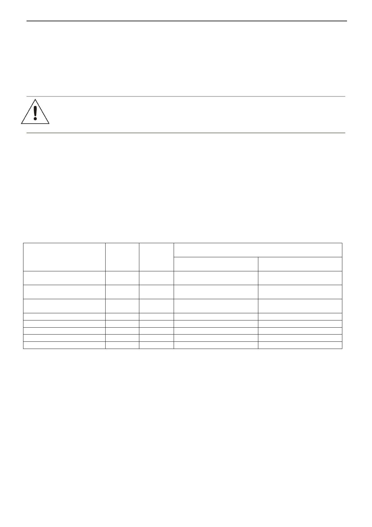
Typical distances between the power supply and the DCDC converter (Table 7):
Cable type:
Cross-
section
[mm
2
]
According
to AWG
The distance between the PSCU04344 power supply unit
and the DC/DC converter:
Current consumption of the
camera: 0,8A/12VDC
Current consumption of the
camera: 1,2A/12VDC
UTP5e twisted pair cable,
one pc
0,2mm
2
24AWG
100 m
60 m
UTP5e twisted pair cable, 2
pcs
0,4mm
2
21AWG
200 m
120 m
UTP5e twisted pair cable, 3
pcs
0,6mm
2
19AWG
300 m
180 m
Stranded cable
0,25mm
2
23AWG
100 m
75m
Stranded cable
0,5mm
2
20AWG
250 m
150m
Stranded cable
0,75mm
2
18AWG
400 m
240m
Stranded cable
1,0mm
2
17AWG
500 m
300m
Stranded cable
1,5mm
2
15AWG
700 m
400m
The distances are given for the rated voltage of Un=230Vac and Ta=20°C.
3. Optical indication.
The PSU is fitted with 4 green L1÷L4 LEDs at the PCB, indicating DC voltage at the AUX1÷AUX4 outputs. During
normal operation, the LED is permanently illuminated. In case of short-circuit or output overload, the LED is off.
4. Service and operation.
4.1 Overload or short-circuit of the power supply output (SCP activation).
The AUX1÷AUX4 outputs of the PSU are individually protected against short-circuit by melting fuses. In case of
fuse replacement, use only compatible replacement parts. If the output load current exceeds Σ4,0A@30V DC (110% ÷
150% of the S power), the F fuse in the 230V AC circuit and/or F1÷F4 fuses become permanently damaged. In case of
failure, replace the fuse with the same type.
4.2 Maintenance.
All maintenance procedures can be performed after disconnecting the power supply from the power network.
The PSU does not require any specific maintenance; however, its interior should be cleaned with compressed air if used
in dusty conditions. In case of fuse replacement, use only compatible replacement parts.
www.pulsar.pl PSCU 04344SEP
7
WEEE MARK
According to the EU WEE Directive It is required not to dispose of electric or electronic waste as
unsorted municipal waste and to collect such WEEE separately.
Pulsar
Siedlec 150, 32-744 Łapczyca, Poland
Phone (+48) 14-610-19-40, Fax (+48) 14-610-19-50
http:// www.pulsar.pl, www.zasilacze.pl
1 / 1

Pulsar PSCU04344SEP Operating instructions

Category
Security device components
Type
Operating instructions

The Pulsar PSCU04344SEP is a reliable power supply unit designed to provide continuous power to 4 HD cameras, with a maximum current efficiency of 4A. It features 4 independent, galvanically isolated outputs, each protected by 1A fuses, ensuring stable operation and protection against short circuits or overloads. The unit operates on a supply voltage of 230V AC and delivers a constant voltage in the range of 30 to 35V DC, making it suitable for powering cameras with varying current requirements.

Ask a question and I''ll find the answer in the document

Finding information in a document is now easier with AI

Ask the document