Dedicated Micros DV-IP Express Quick start guide
- Category
- Digital Video Recorders (DVR)
- Type
- Quick start guide

Quick Start Guide
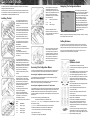
The unit supports Video Inputs via
the 75Ω BNC connectors. Connect
cameras to the video inputs starting
from input 1.
The two rows of connectors provide
video input and loop-through support.
For consistency, DM recommend one
row is used for video inputs and the
other for loop-through connections.
Note: Remember the last piece of
equipment in line must be terminated.
The unit supports a main monitor via
BNC ‘MON A’ and a spot monitor via
BNC ‘MON B’.
Note: The DV-IP RT additionally
supports a main monitor connection via
the HDMI port.
The DV-IP Express additionally
supports a main monitor connection via
the VGA port.
The unit supports two channels of
bi-directional audio (accessible through
NetVu ObserVer). Connect the audio
equipment to the phono sockets AUDIO
IN and AUDIO OUT. The audio channel
defaults to record camera channel 1.
Note: The DV-IP RT additionally
supports real time audio per camera
channel.
The unit has an internal power supply
unit. Connect the mains lead to the
unit and then to the wall socket, or to
a fused spur connection. Check local
regulations before installation. Some
countries require an Alarm/Security
device be connected to a fused spur
and not a wall outlet socket.
Using the
IR Remote Control
The IR Remote Control offers all the control
functionality required to navigate the Conguration and
Viewer menus.
Press the MENU button to access conguration menus
via a connected local monitor. The menu will have
a red indicator highlighting the rst option. Select a
main menu heading to open a drop down list of further
sub-options. Press the Down Directional button to
highlight the next menu option, press OK to open the
highlighted menu.
Press the Right Directional button to highlight the rst
editable parameter on the screen.
Use the Left/Right/Up/Down Directional buttons to
move between elds.
Select OK to start editing a eld (the option will be
outlined in green).
Use the Up/Down Directional buttons to change the
settings within an editable eld.
Numeric elds can be edited with the Directional
buttons. Use the Up/Down Directional buttons to
increase/decrease by an increment of 1, use the
Left/Right Directional buttons to increase/decrease by
an increment of 10.
Use the OK button to accept a new setting. Use the
coloured softkeys to select the accompanying colour
option on screen. To undo changes made to any menu,
select the Refresh (Purple) option.
The following Quick Start Guide will help guide you through the initial installation,
confIguration and operation of the unit.
Use this document in conjunction with the relevant Installation & Operation Guide.
This is located on the Product CD supplied with the unit and can also be found on
the Dedicated Micros website (dedicatedmicros.com).
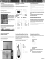
The unit supports 20 normally open/
closed tamper proof alarm inputs, or
one Global keyswitch input with camera
specic inputs congurable as entry/exit
alarms. The alarms support tamper
proof detection using 1k in line and 5K
end of line resistance.
Pin Alarm Input Connection
1 - 20 1-20
21-25 Earth Common
The unit supports a 10/100Mbps auto-
detecting network port. Use a CAT5
cable to connect the unit to the network.
By default the unit is congured for
DHCP (where the unit is automatically
allocated an IP address from the
network DHCP server).
The DNS (Dynamic Name Servers)
function is also supported.
Note: The DV-IP RT additionally
supports a 1Gb Network Connection
(via port ‘NET 1’). Use ‘NET 2’ for
10/100Mbps connections.
The unit supports up to four 24V 200mA
relays.
Pins Connection
1 / 6 Relay 1 signal
2 / 7 Relay 2 signal
3 / 8 Relay 3 signal
4 / 9 Relay 4 signal
Accessing The Conguration Menus
The unit can be congured either on the local monitor or over the network using a
PC with Internet Explorer or similar browser. Both interfaces are near identical.
Accessing the Conguration menus on a local monitor
The Conguration pages can be displayed on the local monitor by pressing the
MENU button on the IR Remote Control.
Note: If the IR Remote Control does not open the menu, press the DVR button to
make sure it is in DVR mode, then press the MENU button.
Accessing the Conguration menus via a PC web browser
The IP address of the unit is required to access the webpages. The DHCP assigned
address can be identied via the local menu pages. Using the local monitor, press
the MENU button on the IR Remote Control and navigate to the System menu.
The DHCP IP address will be displayed. A xed IP address can be assigned via the
Network menu.
To access the unit via DNS, the default address will be:
<machine serial number>.<yourdomain>.com
The <machine serial number> is displayed on the underside of the unit (and on
the System menu page)
<yourdomain> relates to the name assigned to your DNS network.
The default DNS address can be renamed via the Network menu.
1. Launch Internet Explorer (or other web browser package).
2. Type the URL for the unit.
3. The opening menu page will be displayed.
Installing The Unit
When accessing the Conguration
menus, the menu tree will be displayed.
Relevant menus can be accessed
directly via the coloured softkey options
shown at the base of each menu.
The options available will depend
on the menu being viewed. Select a
softkey option by pressing either the
corresponding button on the IR Remote
Control (if viewing the menus locally),
or by selecting the relevant option via
the mouse (if viewing the
webpages).
Navigating The Conguration Menus
Note: Any changes are automatically saved when the page is closed. To ‘manually’
save changes, select the Save option.
Softkey Guidance
The IR Remote Control and optional Keyboard have a common user interface.
In addition to the direct action keys (rewind, fast forward etc.) there are coloured
Softkeys that are context sensitive and enable rapid access to required functions.
To bring up context sensitive Softkey functions at any time, press any of the
coloured keys on the IR Remote Control or Keyboard.
Connect the IR Remote Control
Extender to the IR Input socket. This
must be connected to successfully use
the IR Remote Control.

Quick Start Guide
MI-Q-DVSV/E2-0
Checking the contents of the box
Remove all items from the packaging and check the items listed below are present:
• DV-IP DVR
• IR Remote Control
• IR Remote Control Extender
• USB Mouse
• Power Leads
• Rack mounting brackets
• Serial 9-pin D-type cable
• 2 x RS485 interface modules
• Software disc
• Installation & Operation Guide
• Quickstart Guide
If any of these items are missing, please contact Dedicated Micros Technical
Support team.
Note: Before installing the unit, carefully read all Safety Instructions
and information on where the unit should be located.
Connecting A Dedicated Micros Oracle Dome
A DM Oracle Dome can be connected via either co-axial telemetry or RS485
twisted pair. Oracle Domes are congured using the specic pages available in
the Conguration menus, refer to ‘Oracle Dome Conguration’ in the Installation &
Operation Guide for more information.
The DM Oracle Dome has three address switches, refer to the Oracle Dome
documentation for more information on hardware conguration.
Video Timeline
The Video Timeline allows intuitive, rapid navigation within recorded video. To aid
navigation, the timeline can be set to display periods ranging from 15 seconds to
four weeks. The timeline can be clicked anywhere in the scale to instantly play
recorded images from that point.
Navigation is via a colour coded softkey
system. The coloured menu provides
an intuitive approach to operator and
installer use. The coloured buttons on
the IR Remote Control correspond to
the menu options displayed on screen.
The function of the buttons will change
according to whether the unit is in Live
or Playback mode.
Operating The Viewer
Select the ‘Go To Viewer’ option to open the Viewer menus.
The unit can also be controlled using an optional Dedicated Micros keyboard. This
is connected via the KBD connector on the rear of the unit and provides the same
control functions as the IR Remote Control.
The following keyboards are supported:
DM/KBC1
DM/KBC2
Alarm & Relay Pin Connections
Using Serial Ports
It is possible to connect a variety of telemetry cameras to the unit. Use the
following table as a guide to the serial port connections.
RS232 Connectivity
(Serial 1, 2)
Pin Description Desc
1 Data Carrier Detect DCD
2 Receive Data RX
3 Transmit Data TX
4 Data Terminal Ready DTR
5 Ground GND
6 Data Set Ready DSR
7 Ready to Send RTS
8 Clear to Send CTS
9 Ring Indicate RI
UTC
Red - 1
Blue - N/R
Yellow - N/R
Serial
Red - 2
Blue - Camera Number
Yellow - Camera Number
Using the optional Keyboards
(DM/KBC1 & DM/KBC2)
RS485 Connectivity
(2 wire) (Serial 3, 4)
Pin Description
1 RS485 + (A)
9 RS485 - (B)
5 Shield (GND)
RS232 Connectivity
(Serial 3, 4)
Pin Description Desc
2 Receive Data RX
3 Transmit Data TX
5 Ground GND
7 Ready to Send RTS
8 Clear to Send CTS
1
5
6 9
Connecting Storage Devices
Images are recorded to the internal hard disk for instant playback and searching by
the operator. The capacity of the internal disk effects the amount of images and time
period that can be recorded.
The internal hard disk is a temporary storage device as images are overwritten after
a set period.
If images need to be held for a longer time period, external storage is required. The
SATA ports on the rear of the unit are used to connect to external storage devices.
The unit can support multiple external hard disks. To maintain an effective SATA link,
the length of all cabling from the unit to the connected device should not exceed two
metres.
The unit’s operating system will continue to utilise the internal hard disks if the
external hard drive encounters a problem.
Dedicated Micros Managed Storage Expansion units
A DM Managed Storage Expansion unit is connected via the SATA port. A Managed
Storage Expansion unit provides high capacity, environmentally managed storage
in a single box. Disk temperature is maintained at a constant level and the disk
management system ensures only disks in operation are spun. Both of these
features help extend drive life.
For further information regarding the DM Managed Storage Expansion unit, please
contact Dedicated Micros technical support team.
Virtual Keyboard
If numeric or text data requires entry when viewing menus on a local monitor,
an on-screen virtual keyboard (the Arrow Key Editor) will be displayed. Use the
Directional buttons on the IR Remote Control to move between characters. Use the
OK button to select a character. To enter details and then exit the Virtual Keyboard,
select the OK option. Select Submit to enter details and return to the Virtual
Keyboard. Select Cancel to exit the Virtual Keyboard without entering any text.
-
 1
1
-
 2
2


Dedicated Micros DV-IP Express Quick start guide
- Category
- Digital Video Recorders (DVR)
- Type
- Quick start guide
Ask a question and I''ll find the answer in the document
Finding information in a document is now easier with AI
Related papers
-
Dedicated Micros DV-IP Express Installation & Operation Guide
-
Dedicated Micros DV-IP Operating instructions
-
-
-
-
-
-
-
-