Page is loading ...

LCD TV
Please read this manual carefully before operating your set.
Retain it for future reference.
Record model number and serial number of the set.
See the label attached on the back cover and quote
this information to your dealer
when you require service.
P/NO : 3828TUL309D (0607-REV06)
Printed in Korea
OWNER’S MANUAL
MODELS: 26LX1D 32LX1D
26LX2D 32LX2D
32LP1D 37LP1D 42LP1D
Internet Home Page : http://www.lge.com
http://www.lg.ca
TM

2
Warning
WARNING:
TO REDUCE THE RISK OF ELECTRIC SHOCK DO NOT REMOVE COVER (OR BACK). NO USER
SERVICEABLE PARTS INSIDE. REFER TO QUALIFIED SERVICE PERSONNEL.
The lightning flash with arrowhead symbol, within an equilateral triangle, is intended to alert the user to
the presence of uninsulated “dangerous voltage” within the product’s enclosure that may be of suffi-
cient magnitude to constitute a risk of electric shock to persons.
The exclamation point within an equilateral triangle is intended to alert the user to the presence of
important operating and maintenance (servicing) instructions in the literature accompanying the appli-
ance.
NOTE TO CABLE/TV INSTALLER:
This reminder is provided to call the CATV system installer’s attention to Article 820-40 of the National Electric
Code (U.S.A.). The code provides guidelines for proper grounding and, in particular, specifies that the cable
ground shall be connected to the grounding system of the building, as close to the point of the cable entry as prac-
tical.
REGULATORY INFORMATION
This equipment has been tested and found to comply with the limits for a Class B digital device, pursuant to Part
15 of the FCC Rules. These limits are designed to provide reasonable protection against harmful interference in
a residential installation. This equipment generates, uses and can radiate radio frequency energy and, if not
installed and used in accordance with the instructions, may cause harmful interference to radio communications.
However, there is no guarantee that interference will not occur in a particular installation. If this equipment does
cause harmful interference to radio or television reception, which can be determined by turning the equipment off
and on, the user is encouraged to try to correct the interference by one or more of the following measures:
- Reorient or relocate the receiving antenna.
- Increase the separation between the equipment and receiver.
- Connect the equipment into an outlet on a circuit different from that to which the receiver is connected.
- Consult the dealer or an experienced radio/TV technician for help.
Any changes or modifications not expressly approved by the party responsible for compliance could void the
user’s authority to operate the equipment.
CAUTION:
Do not attempt to modify this product in any way without written authorization from LG Electronics Corporation.
Unauthorized modification could void the user’s authority to operate this product.
U.S.A. only -----------------------------------------------
COMPLIANCE:
The responsible party for this product’s compliance is:
LG Electronics U.S.A., Inc.
1000 Sylvan Avenue, Englewood Cliffs, NJ 07632
Phone: 1-800-243-0000
http://www.lgusa.com
---------------------------------------------------------------
CAUTION
RISK OF ELECTRIC SHOCK
DO NOT OPEN
W
W
arning
arning

3
TV Guide On Screen Notices
TV Guide On Screen Notices
Digital Cable Compatibility
Digital Cable Compatibility
In the United States, TV GUIDE and other related marks are registered marks of Gemstar-TV Guide International,
Inc. and/or one of its affiliates. In Canada, TV GUIDE is a registered mark of Transcontinental Inc., and is used
under license by Gemstar-TV Guide International, Inc.
The TV Guide On Screen system is manufactured under license from Gemstar-TV Guide International, Inc. and/or
one of its affiliates.
The TV Guide On Screen system is protected by one or more of the following issued United States patents
6,498,895, 6,418,556, 6,331,877; 6,239,794; 6,154,203; 5,940,073; 4,908,713; 4,751,578; 4,706,121.
Use of the CableCARD
TM
TradeMark.
“CableCARD
TM
is a trademark of Cable Television Laboratories, Inc.”
This digital television is capable of receiving basic analog, digital basic and digital premium cable television program-
ming by direct connection to a cable system providing such programming. A security card provided by your cable oper-
ator is required to view encrypted digital programming. Certain advanced interactive digital cable services such as
video-on-demand, cable operator enhanced program the TV Guide On Screen system, and data enhanced television
service may require the use of a set top box. For more information contact your local cable operator.

4
Safety Instructions
WARNING :
To Reduce The Risk Of Fire Or Electric Shock, Do Not Expose This Apparatus To Rain Or Moisture.
Apparatus shall not be exposed to dripping or splashing and no objects filled with liquids, such as vases, shall be placed on the
apparatus.
IMPORTANT SAFETY INSTRUCTIONS
1. Read these instructions.
2. Keep these instructions.
3. Heed all warnings.
4. Follow all instructions.
5. Do not use this apparatus near water.
6. Clean only with a dry cloth.
7. Do not block any of the ventilation openings. Install in
accordance with the manufacturer’s instructions.
8. Do not install near any heat sources such as radiators,
heat registers, stoves, or other apparatus (including
amplifiers) that produce heat.
9. Do not defeat the safety purpose of the polarized or
grounding type plug. A polarized plug has two blades
with one wider than the other. A grounding type plug has
two blades and a third grounding prong. The wide blade
or the third prong is provided for your safety. When the
provided plug does not fit into your outlet, consult an
electrician for replacement of the obsolete outlet.
10. Protect the power cord from being walked on or
pinched particularly at plugs, convenience recepta-
cles, and the point where they exit from the apparatus.
11. Only use the attachments / accessories specified by
the manufacturer.
Safety Instructions
Safety Instructions
O
w
n
e
r's
M
a
n
u
a
l

5
Safety Instructions
12. Use only with a cart, stand, tripod, bracket, or table
specified by the manufacturer, or sold with the appa-
ratus. When a cart is used, use caution when moving
the cart / apparatus combination to avoid injury from
tip-over.
13. Unplug this apparatus during lightning storms or when
unused for long periods of time.
14. Refer all servicing to qualified service personnel.
Servicing is required when the apparatus has been
damaged in any way, such as power supply cord or
plug is damaged, liquid has been spilled or objects
have fallen into the apparatus, the apparatus has been
exposed to rain or moisture, does not operate normal-
ly, or has been dropped.
15. DISCONNECTING DEVICE FROM MAINS
Main plug is the disconnecting device.The
plug must remain redily operable.
On Disposal
a. The fluorescent lamp used in this product contains a small amount of mercury.
b. Do not dispose of this product with general household waste.
Disposal of this product must be carried out in accordance to the regulations of your local authority.
Note
- If the TV feels cold to the touch, there may be a small “flicker” when when it is turned on. This is normal, there is noth-
ing wrong with TV.
- Some minute dot defects may be visible on the screen, appearing as tiny red, green, or blue spots. However, they have
no adverse effect on the monitor's performance.
- Avoid touching the LCD screen or holding your finger(s) against it for long periods of time. Doing so may produce some
temporary distortion effects on the screen.
CAUTION concerning the Power Cord
Most appliances recommend they be placed upon a dedicated circuit; that is, a single outlet circuit which powers only that
appliance and has no additional outlets or branch circuits. Check the specification page of this owner's manual to be certain.
Do not overload wall outlets. Overloaded wall outlets, loose or damaged wall outlets, extension cords, frayed power cords,
or damaged or cracked wire insulation are dangerous. Any of these conditions could result in electric shock or fire.
Periodically examine the cord of your appliance, and if its appearance indicates damage or deterioration, unplug it, discon-
tinue use of the appliance, and have the cord replaced with an exact replacement part by an authorized servicer.
Protect the power cord from physical or mechanical abuse, such as being twisted, kinked, pinched, closed in a door, or
walked upon. Pay particular attention to plugs, wall outlets, and the point where the cord exits the appliance.

6
Contents
Contents
Contents
Introduction
Installation
Operation
69 Turning on the TV
69 Volume Adjustment
69 Channel Selection
69 On Screen Menus Language Selection
70 On Screen Menus Selection and Adjustment
71 EZ Scan (Channel Search)
71 Manual Scan
72 Channel Edit
73 DTV Signal Strength
73 Channel Label Setup
74 Main Picture Source Selection
74 Input Label
75 EZ Picture
75 APM (Adaptive Picture Mode)
76 Manual Picture Control (EZ Picture-Custom option)
76 Color Temperature Control
76 Video Reset
77 Audio Language
77 EZ SoundRite
78 EZ Sound
78 Manual Sound Control (EZ Sound-Custom option)
79 Stereo/SAP Broadcasts Setup
79 Front Surround
80 TV Speakers On/Off Setup
80 BBE
2 Warnings
3 TV Guide On Screen Notices / Digital Cable Compatibility
4~5 Safety Instructions
8 Accessories
9 Controls (Model Name: 32/37/42LP1D)
10 Connection Options (Model Name: 32/37/42LP1D)
11 Controls (Model Name: 26/32LX1D, 26/32LX2D)
12 Connection Options (Model Name: 26LX1D/2D)
13 Connection Options (Model Name: 32LX1D/2D)
14~18 Remote Control Key Functions
19 Various Installation
20 How to use back cover
20 Swivel Stand (32/37/42LP1D, 26/32LX2D only)
21 Antenna or Cable Connection
22~23 VCR Setup
24~25 DVD Setup
26~29 HDSTB Setup
30 External AV Source Setup
30 Digital Audio Output
31 Monitor Out Setup (32LX1D/2D, 32/37/42LP1D only)
31 CableCARD
TM
Setup
32~35 PC Setup
36~41 IEEE1394
42~43 G-LINK
TM
Setup
44~50 TV Guide On Screen
TM
System Setup
51~68 TV Guide On Screen
TM
System Feature
Setup Menu
Options
Video Menu
Options
Audio Menu
Options
Basic operation
External
Equipment
Connections
Installation
Instruction

7
Contents
Reference
81 Auto Clock Setup
81 Manual Clock Setup
82 On/Off Timer Setup
82 Sleep Timer
83 Auto Off
84 Aspect Ratio Control
85 Cinema 3:2 Mode Setup
85 Caption
86 Caption/Text
87 Caption Option
87 Auto Demo (Review)
88 Logo Light
88 Freeze & Magnify (DTV/CADTV 720p or 1080i mode only)
89~90 Parental Lock Setup
91 Cable Menu Options
91 Scrambled Channel
92 Cable Channel List
92 Emergency Alert Message
93 Brief Info.
94 Watching PIP/POP/Twin Picture
94 Selecting an Input Signal Source for PIP/Twin Picture
94 TV Program Selection for PIP
94 Moving the PIP Sub Picture
95 Adjusting Main and Sub Picture Sizes for Twin Picture
95 Swapping the PIP/Twin Picture
95 POP (Picture-out-of-Picture: Channel Scan)
Notes on Memory card
96 What is Memory Card
96 Precaution for Using the Memory Card
97 Insert/Eject Memory Card
98 Supported Files
Mode
98 Basic Operation
JPEG File Viewing Options
99 Photo List OSD Display
99 Picture Selection and Popup menu
MP3 Files Playing Operation
100 Music List OSD Display
101 MP3 File Selection and Popup menu
101 Screen Saver
102~107 External Control Device Setup
108~109 IR Codes
110 Programming the Remote
111~112 Programming Codes
113~114 Troubleshooting Checklist
115 Maintenance
115 Product Specifications
Option Menu
Features
Lock Menu Options
PIP (Picture-in-
Picture)/POP/
Twin Picture
CableCARD
TM
Function
Brief Info.
Operation
Time Menu
Options

8
Introduction
Accessories
Accessories
Introduction
Introduction
Owner’s Manual
75Ω Round Cable
G-LINK CablePower Cord
Ensure that the following accessories are included with your TV. If any accessory is missing, please contact the
dealer from where you purchased the product.
User must use the shield signal interface cable (D-sub 15 pin cable) with ferrite cores to maintain a standard com-
pliance for the product.
1.5V
1.5V
TV INPUT
TV/VIDEO
VOL
FLASHBK
CH
POWER
1 2 3
456
78
0
9
ADJUST
RATIO SWAP
TIMER
PIP CH+PIP CH-
PIP
SAP
CC
M/C EJECT
FREEZE
AUTO DEMO
EZ PIC
APM
EZ SOUND
PIP INPUT
A
U
D
IO
D
A
Y
-
CABLE
M
E
NU
MUTE
PAGE
PAGE
FAV
TV GUIDE
VCR
DA
Y+
STB
EXIT
1394
M
A
R
K
TV
DVD
MODE
IN
FO
i
ENTER
Remote Control /
Batteries
Twister Holder
Arrange the wires
with the twister holder.
Polishing Cloth
Polish the TV with the cloth.
- Slightly wipe stained spot on the exterior only
with the cleansing cloths for the product exterior
if there is stain or fingerprint on surface of the
exterior.
- Do not wipe roughly when removing stain.
Please be cautious of that excessive power may
cause scratch or discoloration.
D-sub 15 pin Cable
Option Extras

9
Introduction
Controls
Controls
(Model Name: 32/37/42LP1D)
(Model Name: 32/37/42LP1D)
- This is a simplified representation of front panel.
- Here shown may be somewhat different from your TV.
CH VOL
TV/VIDEO/
TV
GUIDE
ON/OFF
RR AUDIOAUDIO VIDEOVIDEO
S-VIDEOS-VIDEO
L/MONO
VIDEO2
MENU
1394
IEEE
Power Standby Indicator
Illuminates red when the TV is in standby mode. When the TV
is switched on, blinks green and then illuminates green.
Remote Control Sensor
TV GUIDE Button
VOLUME (
F,G) Buttons
CHANNEL (E, D) Buttons
Memory Card Slot
(For mode)
MENU Button
ON/OFF Button
S-VIDEO Input
Audio/Video Input 2
Logo Light
Channel Display
TV/VIDEO / Button
DTV, CADTV mode
TV, CATV mode
Video1-2 mode
Component1-2 mode
PC mode
HDMI mode
IEEE1394
Surround mode
mode
1394
IEEE

10
Introduction
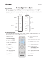
Connection Options (Model Name: 32/37/42LP1D)
Connection Options (Model Name: 32/37/42LP1D)
R
L
COMPONENT2
VIDEO
AUDIO
ANTENNA
G-LINK
DIGITAL AUDIO
(OPTICAL)
DVI
INPUT
COMPONENT1
INPUT
OUTPUT
VIDEO1
RGB INPUT
(PC/DTV INPUT)
RS-232C INPUT
(CONTROL/SERVICE)
AUDIO INPUT
AUDIO
(MONO)
VIDEO INPUT
COMPONENT1
RL
RL
PC AUDIO
INPUT
REMOTE
CONTROL
S-VIDEO
CableCARD
IEEE
1394
CABLE
AC IN
MONITOR
OUT
VIDEO
HDMI
* The HDMI port can receive video via High-Definition Multimedia Interface (HDMI) or the Digital Visual Interface
(DVI). Note: An adapter or special cable is required to plug DVI into an HDMI port (available at home theater or
computer stores).
COMPONENT2
(VIDEO / AUDIO Input)
DIGITAL AUDIO OUTPUT
/ DVI INPUT
/ COMPONENT1 INPUT
AUDIO/VIDEO INPUT1
COMPONENT1 (VIDEO / AUDIO INPUT)
MONITOR OUT
HDMI / IEEE1394 Port
CableCARD
TM
Slot
ANTENNA Input
CABLE Input
AC IN
G-LINK
TM
Port
PC AUDIO INPUT
RS-232C INPUT (CONTROL/SERVICE) /
RGB INPUT (PC/DTV INPUT)
REMOTE CONTROL Port
- Here shown may be somewhat different from your TV.

11
Introduction
Controls
Controls
(Model Name: 26/32LX1D, 26/32LX2D)
(Model Name: 26/32LX1D, 26/32LX2D)
- This is a simplified representation of front panel.
- Here shown may be somewhat different from your TV.
CH
VOLVOL MENUMENU
TV/ VIDEO/ TV GUIDE
ON/OFFON/OFF
VOLUME (F,G) Buttons
Remote Control Sensor
/Power Standby Indicator
Illuminates red when the TV is in
standby mode.
When the TV is switched on, blinks
green and then illuminates green.
CHANNEL (E, D) Buttons
MENU Button
ON/OFF Button
TV GUIDE Button
TV/VIDEO
/ Button

12
Introduction
Connection Options (Model Name: 26LX1D/2D)
Connection Options (Model Name: 26LX1D/2D)
* The HDMI port can receive video via High-Definition Multimedia Interface (HDMI) or the Digital Visual Interface
(DVI). Note: An adapter or special cable is required to plug DVI into an HDMI port (available at home theater or
computer stores).
ANTENNA
G-LINK
DIGITAL AUDIO
(OPTICAL)
OUTPUT
VIDEO1
RGB INPUT
(PC/DTV INPUT)
RS-232C INPUT
(CONTROL/SERVICE PORT)
AUDIO INPUT
VIDEO INPUT
RL
PC AUDIO
INPUT
REMOTE
CONTROL
S-VIDEO
CableCARD
IEEE
1394
CABLE
AC IN
AUDIO VIDEO
(MONO)
RL
HDMI
DVI INPUT
COMPONENT1 INPUT
COMPONENT1
R
(MONO)
L VIDEO
S-VIDEO
VIDEO
AUDIO
COMPONENT 2
VIDEO 2
COMPONENT2
(VIDEO Input)
AUDIO Input
VIDEO2
S-VIDEO
Memory
Card Slot
(Formmmm
mode)
DIGITAL AUDIO OUTPUT / DVI INPUT
/ COMPONENT1 INPUT
AUDIO/VIDEO INPUT1
COMPONENT1 (VIDEO / AUDIO INPUT)
HDMI / IEEE1394 Port
CableCARD
TM
Slot
ANTENNA Input
CABLE Input
AC IN
G-LINK
TM
Port
PC AUDIO INPUT
RS-232C INPUT (CONTROL/SERVICE) /
RGB INPUT (PC/DTV INPUT)
REMOTE CONTROL Port
- Here shown may be somewhat different from your TV.

13
Introduction
Connection Options (Model Name: 32LX1D/2D)
Connection Options (Model Name: 32LX1D/2D)
ANTENNA
G-LINK
DIGITAL AUDIO
(OPTICAL)
DVI
INPUT
COMPONENT1
INPUT
OUTPUT
VIDEO1
RGB INPUT
(PC/DTV INPUT)
RS-232C INPUT
(CONTROL/SERVICE)
AUDIO INPUT
AUDIO
(MONO)
VIDEO INPUT
COMPONENT1
RL
RL
PC AUDIO
INPUT
REMOTE
CONTROL
S-VIDEO
CableCARD
IEEE
1394
CABLE
AC IN
MONITOR
OUT
VIDEO
HDMI
R
(MONO)
L VIDEO
S-VIDEO
VIDEO
AUDIO
COMPONENT 2
VIDEO 2
COMPONENT2
(VIDEO Input)
AUDIO Input
VIDEO2
S-VIDEO
Memory
Card Slot
(Formmmm
mode)
* The HDMI port can receive video via High-Definition Multimedia Interface (HDMI) or the Digital Visual Interface
(DVI). Note: An adapter or special cable is required to plug DVI into an HDMI port (available at home theater or
computer stores).
DIGITAL AUDIO OUTPUT
/ DVI INPUT
/ COMPONENT1 INPUT
AUDIO/VIDEO INPUT1
COMPONENT1 (VIDEO / AUDIO INPUT)
MONITOR OUT
HDMI / IEEE1394 Port
CableCARD
TM
Slot
ANTENNA Input
CABLE Input
AC IN
G-LINK
TM
Port
PC AUDIO INPUT
RS-232C INPUT (CONTROL/SERVICE) /
RGB INPUT (PC/DTV INPUT)
REMOTE CONTROL Port
- Here shown may be somewhat different from your TV.

14
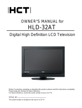
Introduction
Remote Control Key Functions
Remote Control Key Functions
POWER
Turns your TV or any other programmed equipment on or
off, depending on mode.
TV INPUT
TV/VIDEO
VOL
FLASHBK
CH
POWER
1 2 3
4 5 6
78
0
9
ADJUST
RATIO SWAP
TIMER
PIP CH+PIP CH-
PIP
SAP
CC
M/C EJECT
FREEZE
AUTO DEMO
EZ PIC
APM
EZ SOUND
PIP INPUT
AUDIO
DAY -
CABLE
MENU
MUTE
PAG E
PAG E
FAV
TV GUIDE
VCR
DAY+
STB
EXIT
1394
MARK
TV
DVD
MODE
INFO
i
ENTER
TV INPUT
Rotates the input mode between Antenna and Cable. In
Video1-2, Component 1-2, RGB-DTV (or RGB-PC), HDMI/DVI,
and IEEE1394 input sources, screen returns to the last TV
channel.
MODE
Selects the remote operating mode: TV, VCR, DVD, CABLE,
STB or AUDIO.
TV/VIDEO (Refer to p.17)
External input modes rotate in regular sequence: Antenna,
Cable, Video1-2, Component 1-2, RGB-DTV (or RGB-PC),
HDMI/DVI). (Video 1-2, Component 1-2 input sources are linked
automatically, Only if these are connected)
EXIT
Clears all on-screen displays and returns to TV viewing from
any menu.
1394 (Refer to p.36~41)
Use it to operate the DVHS, MicroMV camcorder and DSTB.
INFO (Refer to p.93)
When you watch the TV, information displays on top of the
screen. Not available in Component 1-2, RGB and HDMI/DVI
mode.
MENU
Brings up the main menu to the screen. Enters or exits a
Panel Menu in the TV Guide On Screen system.
TV GUIDE
Brings up the TV Guide On Screen system to the screen.
THUMBSTICK (Up/Down/Left/Right/ENTER)
Allows you to navigate the on-screen menus and adjust the
system settings to your preference.
NUMBER BUTTONS
LIGHT
Illuminates the remote control buttons.

15
Introduction
TIMER (Refer to p.82)
Lets you select the amount of time before your TV turns
itself off automatically.
RATIO (Refer to p.84)
Changes the aspect ratio.
ADJUST (Refer to p.35)
Adjusts screen position, size, and phase in PC mode.
FAV
Use to scroll the Favorite channels.
MUTE (Refer to p.18)
Switches the sound on or off.
CHANNEL UP/DOWN
Selects available channels found with EZ scan and Manual scan.
PAGE UP/DOWN
Moves from one full set of screen information to the next one.
VOLUME UP/DOWN
Increases/decreases the sound level.
TV INPUT
TV/VIDEO
VOL
FLASHBK
CH
POWER
1 2 3
4 5 6
78
0
9
ADJUST
RATIO SWAP
TIMER
PIP CH+PIP CH-
PIP
SAP
CC
M/C EJECT
FREEZE
AUTO DEMO
EZ PIC
APM
EZ SOUND
PIP INPUT
AUDIO
DAY -
CABLE
MENU
MUTE
PAG E
PAG E
FAV
TV GUIDE
VCR
DAY+
STB
EXIT
1394
MARK
TV
DVD
MODE
INFO
i
ENTER
Mode Control Buttons
Controls the Mode.
For further details, see the ‘ Mode’ section.
— (DASH)
Used to enter a program number for multiple program chan-
nels such as 2-1, 2-2,etc.
FLASHBK
Returns to the last channel viewed.
VCR/DVD/DVHS/Camcorder BUTTONS
Control some video cassette recorders or DVD players
("RECORD" button is not available for DVD player).
Control DVHS or camcorders while in IEEE 1394 mode.
DAY + / DAY-
Moves forward or backward in 24 hour increments.
Enter to the Mode.
MARK
Selects a photo or music you want to view or play in
mode.
M/C EJECT
When removing the memory card, this button is used.

16
CC (Refer to p.86)
Select a closed caption: Off, CC1~4, Text1~4.
FREEZE
Freezes the currently-viewed picture. Main picture is frozen
in PIP/Twin picture mode.
AUTO DEMO (Refer to p.87)
Displays the slide show to explain the main features of this TV.
VOL
FLASHBK
CH
1 2 3
4 5 6
78
0
9
ADJUST
RATIO SWAP
TIMER
PIP CH+PIP CH-
PIP
SAP
CC
M/C EJECT
FREEZE
AUTO DEMO
EZ PIC
APM
EZ SOUND
PIP INPUT
MUTE
PAG E
PAG E
FAV
PIP (Refer to p.94)
Switches between PIP, POP (Picture-out-of-Picture) and
Twin picture modes. Switches the video window locking or
unlocking in the Listings Grid.
PIP CH-/PIP CH+ (Refer to p.94)
Changes to next higher/lower PIP channel.
PIP INPUT (Refer to p.94)
Selects the input source for the sub picture in PIP/Twin pic-
ture mode.
SWAP (Refer to p.95)
Exchanges the main/sub images in PIP/Twin picture mode.
SAP (Refer to p.79)
Selects MTS sound: Mono, Stereo, and SAP in analog mode.
Change the audio language in DTV mode.
EZ PIC (Refer to p.75)
Selects a factory preset picture mode depending on the view-
ing environment.
APM (Refer to p.75)
Concurrently, compare with the Daylight, Normal, Night Time
and Custom on the screen.
EZ SOUND (Refer to p.78)
Selects the sound appropriate for the program's character.
Introduction
Installing Batteries
Open the battery compartment
cover on the back side.
Insert two batteries in correct
polarity (+ with +, - with -). Don’t
mix old or used batteries with new
ones.
Close the cover.
* Use a remote control 7 meter distance
and 30 degree (left/right) within the
receiving unit scope.
* Dispose of used batteries in a recycle
bin to prevent environment.
TV INPUT
TV/VIDEO
POWER
A
U
D
IO
D
A
Y
-
CABLE
M
E
N
U
T
V
G
U
ID
E
V
C
R
D
A
Y
+
S
T
B
TV
DVD
MODE
ENTER
1
2
3
i.e)

17
Introduction
TV INPUT
TV/VIDEO
VOL
FLASHBK
CH
POWER
1 2 3
4 5 6
78
0
9
ADJUST
RATIO SWAP
TIMER
PIP CH+PIP CH-
PIP
SAP
CC
M/C EJECT
FREEZE
AUTO DEMO
EZ PIC
APM
EZ SOUND
PIP INPUT
AUDIO
DAY -
CABLE
MENU
MUTE
PAG E
PAG E
FAV
TV GUIDE
VCR
DAY+
STB
EXIT
1394
MARK
TV
DVD
MODE
INFO
i
ENTER
1. When every external equipment is connected:
2. When any external equipment is not connected:
Auto Link
TV Video1 Video2 Component1
HDMI/DVI Component2RGB-DTV (or RGB-PC)
3. When some External Equipment is connected:
(ex: When connected to Video 2)
TV
RGB-DTV (or RGB-PC)
Video2
HDMI/DVI
TV RGB-DTV (or RGB-PC) HDMI/DVI
• You can also select Main Input in the SETUP menu.
• Antenna: Select it when watching the TV/DTV.
•
Cable: Select it when watching the CATV/CADTV.
• Video1-2: Select it when watching the VCR or external equip-
ment.
•
Component 1-2: Select it when using the DVD or the Digital
set-top box depend on connector.
•
RGB-PC / RGB-DTV: Select it when using PC or Digital set-top
box depend on connector.
• HDMI / DVI: Select it when using DVD, PC or Digital set-top
box depend on connector.
SETUP
VIDEO
AUDIO
TIME
OPTION
LOCK
CABLE
Previous
MENU
EZ Scan
Manual Scan
Channel Edit
DTV Signal
Channel Label
Main Input
G
Sub Input
Input Label
Set ID
Antenna
Cable
Video1
Video2
Component1
Component2
RGB-PC
HDMI/DVI

18
Introduction
TV INPUT
TV/VIDEO
VOL
FLASHBK
CH
POWER
1 2 3
4 5 6
78
0
9
ADJUST
RATIO SWAP
TIMER
PIP CH+PIP CH-
PIP
SAP
CC
M/C EJECT
FREEZE
AUTO DEMO
EZ PIC
APM
EZ SOUND
PIP INPUT
AUDIO
DAY -
CABLE
MENU
MUTE
PAG E
PAG E
FAV
TV GUIDE
VCR
DAY+
STB
EXIT
1394
MARK
TV
DVD
MODE
INFO
i
ENTER
EZ Mute
- When you repeatedly press the MUTE button, the sound
mode is changed in turn. (Refer to the picture below)
Mute: Sound is muted.
Mute
EZ Mute: A special mute
mode to activate the closed
caption automatically.
Mute Off: Sound is enabled.
Note: EZ Mute does not operate in Component/RGB/HDMI/DVI
modes.
EZ Mute
24

19
Introduction
Installation
Installation
Various Installation
For proper ventilation, allow a clearance of 4" on each side and from the wall. Detailed installation instructions
are available from your dealer, see the optional Tilt Wall Mounting Bracket Installation and Setup Guide.
Wall Mount: Horizontal installation
Desktop Pedestal Installation
4 inches
4 inches4 inches
4 inches
4 inches
4 inches4 inches
4 inches
4 inches
4 inches4 inches
4 inches
4 inches
4 inches
4 inches4 inches
4 inches
4 inches
4 inches
4 inches4 inches
4 inches
4 inches
4 inches
4 inches4 inches
4 inches
For proper ventilation, allow a clearance of 4" on each side and from the wall.

20
Installation
How to use back cover
Antenna
LOOP THROUGH
UPGRADE
PORT
HDMI
MONITOR
OUT
REMOTE
CONTROL
DVI INPUT
(PC INPUT)
PC SOUND
AV1
AV2
VIDEO
L
AUDIO
R
Hold the cover with both hands and pull it
backward.
1
Install wires as necessary.
(To install various wires, refer to
p.21~41.)
2
Antenna
LOOP THROUGH
UPGRADE
PORT
HDMI
MONITOR
OUT
REMOTE
CONTROL
DVI INPUT
(PC INPUT)
PC SOUND
AV1
AV2
VIDEO
L
AUDIO
R
Reinstall the cover.
4
Antenna
LOOP THROUGH
UPGRADE
PORT
HDMI
MONITOR
OUT
REMOTE
CONTROL
DVI INPUT
(PC INPUT)
PC SOUND
AV1
AV2
VIDEO
L
AUDIO
R
Align the holes on the TV back panel
with the protuberances on the back
cover and insert.
3
- The TV can be conveniently swivelled on its stand 30° to the left or right to provide the optimum viewing angle.
Swivel Stand (32/37/42LP1D, 26/32LX2D only)
Wire Arrangement
- Pull the cables through the hole on the set.
* Arrange the signal input
cable and the power cord
by holder, as shown.
Option
/