Wolf Garten Robo Scooter 400 Original Operating Instructions
- Category
- Lawnmowers
- Type
- Original Operating Instructions
Page is loading ...
Page is loading ...
Page is loading ...

Table of Contents
1. Introduction And Safety ......................................................................................................................................................... 3
2. Know Your Unit ......................................................................................................................................................................... 6
3. Planning Ahead ......................................................................................................................................................................... 9
4. Initial Setup.............................................................................................................................................................................. 15
5. Preparing Your Unit .............................................................................................................................................................. 26
6. Operation ................................................................................................................................................................................. 29
7. Using the Power Box ............................................................................................................................................................ 37
8. Charging ................................................................................................................................................................................... 38
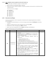
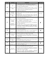
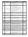
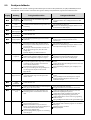
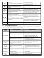
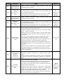
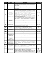
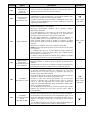
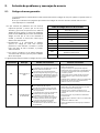
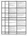
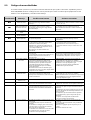
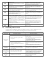
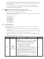
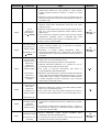
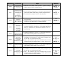
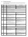
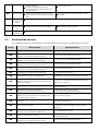
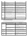
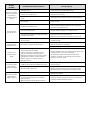
9. Troubleshooting and User Messages ............................................................................................................................. 39
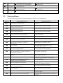
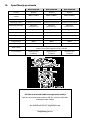
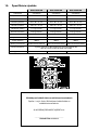
10. Product Specification ....................................................................................................................................................... 46
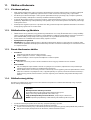
11. Maintenance and Storage .............................................................................................................................................. 47
12. Accessories .......................................................................................................................................................................... 50
13. Tips for maintaining your lawn ..................................................................................................................................... 51
14. Warranty ............................................................................................................................................................................... 52

1. Introduction And Safety
Introduction
1.1.
Product, product specifications and this document are subject to change without notice. All other trademarks are
property of their respective owners.
Welcome to the world of home robotics!
Thank you for purchasing our product. We know that you will enjoy the extra free time you will have while using the
unit
to mow your lawn. When set up and used properly, the unit
will operate safely on your lawn and provide you with
a quality of cut matched by a few mowers of any kind. You will be impressed with your lawn’s appearance and best of
all, the unit did it for you.
IMPORTANT!
The following pages contain important safety and operating instructions. Please read and follow all instructions in
t
his manual. Carefully read and review all safety instructions, warnings and cautions contained in this manual.
Failure to read and follow these instructions, warnings and cautionary statements may result in severe injury or
death to persons and pets or damage to personal property.
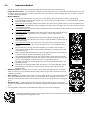
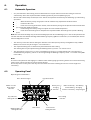
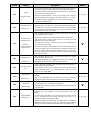
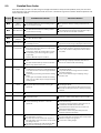
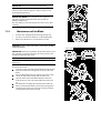
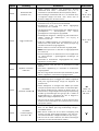
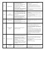
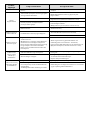
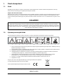
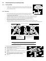
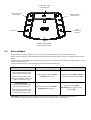
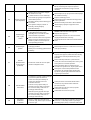
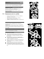
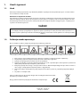
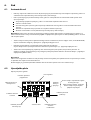
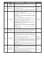
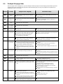
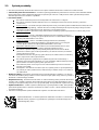
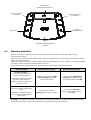
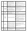
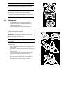
Warning Decal Definitions
1.2.
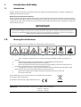
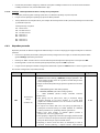
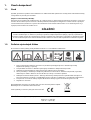
These are the symbols on the unit; Read them carefully before operating the unit.
1 2 3 4 5 6 7
1. This is a dangerous power tool. Use care when operating and follow all safety instructions and
warnings.
2. Read through the Operating & Safety Manual carefully before operating the unit.
3. Hazard of throwing or flying objects while in operation.
4. Keep a safe distance from the unit when operating. Keep people in particular children, pets and
bystanders away from the area in which the unit is being used.
5. Severing of toes or fingers – Rotary mower blade. Risk of injury from rotating cutting blade. Keep
hands and feet away and do not attempt to lift the unit from this area.
6. Operate the disabling device before working on or lifting the unit (see section 1.4)
7. Do not ride on the unit.
Do not dispose the unit or any other part of it as unsorted municipal waste –
I
t should be collected separately.
This product conforms to the applicable EU Directives
IMPORTANT! All units of measure in this manual are American measurements.
1feet (ft.) = 30,48 cm
1 inch (in“) = 2,54 cm.

Safety Warnings & Precautions
1.3.
Training -
1. Read this Operating and Safety Manual carefully before operating the unit. Be familiar with the controls and the proper use
of the unit.
2. Never allow people unfamiliar with these instructions or children to use the unit.
3. The operator or user is responsible for accidents or hazards occurring to other people or their property.
Preparation –
1. Ensure the correct installation of the Perimeter Wire system as instructed.
2. Periodically inspect the area where the unit is to be used and remove all stones, sticks, wires, bones, and other foreign
objects.
3. Periodically visually inspect to see that the blade is not worn or damaged. Replace worn or damaged blade in sets to
preserve balance.
Operation –
1
. Do not operate the unit if any safety feature or any part is damaged, worn or inoperable.
2. Keep hands and feet away from the cutting blade and other moving parts.
3. Never pick up or carry the unit while the motors are running.
4. Do not leave the unit to operate unattended if you know that there are pets, children or people in the vicinity.
5. Never mow while people, especially children, or pets are nearby.
6. Always switch off the Safety Switch before lifting the mower or attempting any adjustments.
7. Do not touch the blade before the blade has come to a complete stop.
8. Do not use the unit for any purpose other than for which it is intended.
9. Keep all guards, shields, safety devices, and sensors in place. Repair or replace damaged parts, including decals.
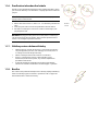
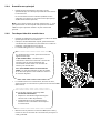
Transportation –
To safely move from or within the working area:
1. Press the STOP button to stop the unit.
2. Use the Remote Control (available as an accessory) to drive it from place to place.
3. In case of different height level, switch off the Safety Switch, and carry the mower by the
carrying handle.
4. In case of long transportation, use the original packaging.
5. When transporting the unit over long distances switch off the Safety Switch.
IMPORTANT! After turning on the Safety Switch, always re-set the current day and time.
Failure to do so may result in non-intentional operation of the unit.
Using Remote Control (Manual Mowing)
1
. Mow only in daylight or in a good artificial light and avoid operating in wet grass.
2. Do not operate the unit when barefoot or wearing open sandals. Always wear substantial footwear and long trousers;
always be sure of your footing on slopes.
3. Use extreme caution when reversing the mower towards you.
4. Always switch on the motor according to instructions with feet well away from the blade.
5. Do not mow manually in slope greater than 15 degrees or where a firm footing is not possible.
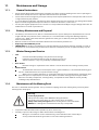
Maintenance and Special Instructions –
1. Always switch off the Safety Switch of the unit before clearing blockage/ checking/ cleaning/ working on the unit or
replacing the blade. Never attempt to service or adjust the mower while it is in operation.
2. In case of abnormal vibrations, stop the mower, switch off the Safety Switch and check for any damage of the blade. Replace
worn or damaged blade to preserve balance. If vibration continues, call for service.
3. Use heavy gloves when inspecting or servicing the blade.
4. Do not perform maintenance when barefoot or wearing open sandals. Always wear suitable work shoes and long trousers;
5. Replace worn or damaged parts for safety.
6. Use only the original equipment and accessories. It is not permitted to modify the original design of the unit. All
modifications are made at your own risk.
7. Maintenance/ Servicing / Cleaning of the unit should be according to manufacturer's instructions.
8. Keep all nuts, bolts and screws tight to be sure the machine is in safe working condition.
9. Warning! When there is a risk of a lightning storm, disconnect the Perimeter Wire from the Base Station / Perimeter Switch
and the Power Box 230V/120V plug from the power outlet.

Batteries –
1. Do not open or damage the battery pack.
2. The battery pack should be replaced by a service dealer only.
3. The Battery Pack contains electrolytes. In case of an electrolyte leakage from the battery pack, the actions described below
are required:
Skin contact: Wash the contact areas off immediately with plenty of water and soap.
Eye contact: Flush the eyes with plenty of clean water for at least 15 minutes immediately, without rubbing.
Get medical treatment.
4. Ensure that the battery pack is charged using the correct charger recommended by the manufacturer. Incorrect use may
result in electric shock, overheating or leakage of corrosive liquid from the battery.
Product End of Use –
1. Unit and its accessories should be collected separately at the end of their life to prevent waste electrical and electronic
equipment from ending up in landfill sites, to promote the reuse, treatment and recovery of electrical and electronic
equipment with the purpose to preserve, protect and improve the quality of the environment, protect human health and
utilize natural resources prudently and rationally.
2. Do not dispose the unit or any other part of it (including the Power Box, Base Station and Perimeter Switch) as unsorted
municipal waste – it should be collected separately.
3. Ask your local distributor/dealer about return and collection systems available.
4. Do not dispose the battery pack in a fire and do not place used batteries in your household trash.
5. The battery must be collected, recycled, or disposed of in an environmentally sound manner.
Safety Features
1.4.
Child Lock
1.
The Child Lock prevents unintended operation of the unit by an accidental press of one of the buttons. Only pressing of two
buttons in a certain order will initiate the operation.
Anti-Theft / Disabling Device
2.
The Anti-Theft / Disabling Device system provides the user a disabling function that will prevent anyone from using or
driving the unit unless they have the valid code to enter. You will be prompted to enter a four digit code of your choice to
use as your personal security code.
Lift Sensor
3.
In the event the unit is raised from the ground during blade operation, the blade will stop rotating immediately.
Tilt Sensor
4.
In case the unit is tilted up towards a vertical position, the blade will stop immediately.
Obstruction Sensor
5.
The unit detects when there is an obstacle in its way during operation. When the mower collides with an obstacle, the unit
will stop the rotation of the blade immediately, will stop movement in that direction and reverse itself away from the
obstacle.
Emergency Stop Button
6.
Pressing the STOP button at any time during operation will stop the unit and the blade immediately.
Safety Switch
7.
Switching off the Safety Switch will prevent any operation of the unit. It is required to switch it off before lifting the unit and
before any maintenance is done.
Sealed Batteries
8.
The batteries that operate the unit are completely sealed and will not leak any type of fluids, regardless of position.
Base Station / Perimeter Switch and Perimeter Wire
9.
The unit cannot operate without a Perimeter Wire installed and activated through the Base Station / Perimeter Switch.
In the event the Perimeter Switch is turned off or otherwise fails to function, the unit will stop operating.

2. Know Your Unit
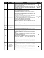
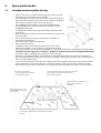
How Your Unit Works for You
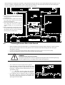
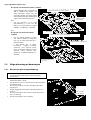
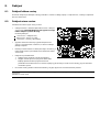
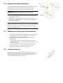
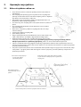
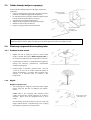
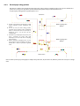
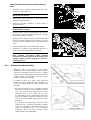
2.1.
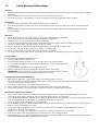
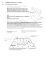
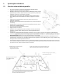
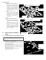
• First, you need to install a perimeter wire around the entire lawn and
around protected areas within the lawn area.
• The Perimeter Wire sets the boundaries for the unit. The Perimeter Wire
is laid around the edges of the lawn and around trees, plants, ponds
and objects that you want to prevent the unit to run into.
• If the supplied wire is not sufficient, more wire can be purchased and
spliced with a supplied connector to the existing wire.
• Small pegs are used to fasten the Perimeter Wire into the ground,
below grass level.
• The Perimeter Wire will gradually disappear under the growth of new
grass until it will be invisible.
• The Base Station is placed along the Perimeter Wire. It performs two
basic functions:
• Generate a signal along the Perimeter Wire.
• Charge the unit’s batteries.
• The Power Box is connected between the Base Station and a 230V /
120V wall socket, using a 15m (50 ft.) long low voltage cable.
• After having completed the installation of the Perimeter Wire, Base
Station, and the Power Box, and performing the One-Time Setup [needs to be performed before operating the
unit for the first time – detailed instructions are in the following chapters], the unit will do all the mowing for
you for during the entire season!
• The unit is a robotic lawn mower that is powered by a maintenance-free battery. It leaves its Base Station at
scheduled mowing times. The unit mows the lawn and then drives back to the Base Station to be charged and
ready for its next scheduled mowing.
• As soon as the unit departs for mowing, the Base Station automatically triggers a special signal. This signal
creates a virtual wall, visible only to the unit. This signal keeps the unit within the lawn boundaries, and prevents
it from entering areas it was intended to skip or protect.
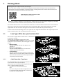
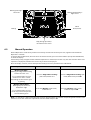
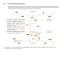
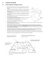
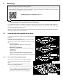
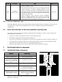
Perimeter Wire
Peg
Base Station and Power Box:
- Generates signal along the wire
- Charges units’ battery
Large trees: The unit is allowed to bump into them, at this
size, the objets do not require a Perimeter Wire around
them
The unit detects the signal and
changes direction as it reaches the
wire
Tree surrounded by a groove, dicht or flower beds requires a
wire around it
Perimeter wire as a virtual wall,
visible only to the unit

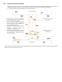
Operation Method
2.2.
• The unit
is a robotic lawnmower designed to mow and maintain your lawn completely by it.
• Simple One-Time Setup – The unit
requires a simple one time setup, which can easily be done by the consumer. The unit
recognizes the wire using special sensors, and makes sure it always stays inside the designated area. Essential accessories
are supplied with the product.
• Working Method –
The unit will automatically mow the lawn. It continuously alternates between mowing and charging.
It independently leaves the Base Station and cuts the lawn by moving around it in a random pattern, until the
entire area looks evenly cut.
Edge Cutting - Unlike other robotic lawn mowers, this unit
is the only mower that has a special Edge mode, in
which it follows the perimeter wire for complete coverage of the lawn edges. The unit
is the only the mower to
cut outside the wheels.
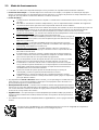
Strong Cutting System -The unit’s extra sharp blade enables to perform the first cut of the season, when the
grass is relatively high.
TurboMow Mode - TurboMow feature allows faster and stronger mowing of a high
grass during the first cut of the season (see P026 in Section 6.4.2 for more
information).
SmartMow Mode - SmartMow feature allows more efficient mowing operation
through smooth and continuous turns at lawn’s edge (see P024 in Section 6.4.2 for
more information).
Search the Base Station -The unit starts to search for the Base Station when the
battery capacity becomes low. It does not mow when it is searching for the Base
Station.
The unit will then recharge and proceed mowing as needed. It will continue in
mowing until completing the required mowing time for your lawn (based on the
area you have set).
When completing the mowing of the entire area (Mowing Cycle), the unit will stay
in the Base Station until the next Mowing Cycle will start.
Unit completes two Mowing Cycles per week in order to keep your lawn healthy
and good looking. However if your lawn requires more time to maintain your lawn,
you can easily adjust the time the unit runs in a single Mowing Cycle.
The Operating Panel on the top of the unit is where you manage the mower and
operating settings.
Availability- The mowing width of the unit (28cm / 11”) and the powerful cutting
system help the unit to finish the job very fast and leave your lawn free for the
family to enjoy.
• A Remote Control is available as an accessory and is used for driving the unit
to a separated
z
one, if necessary. It is also used for mowing small patches of grass that cannot be reached in
automatic operation.
• Grass cycling -The unit
cuts the grass into very small clippings that are buried in the roots of the
lawn, where they decompose and act like a natural fertilizer. Grass clippings contain 80-85%
water and release valuable nutrients that return back into the soil. It is the natural recycling of
grass.
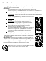
• Robomow® App – a mobile application (available for Android and iOS), which enables user
friendly and intuitive operation of your unit, and opens additional menu options and features the
unit.
• For compatibility information of the Robomow® App please visit the unit webpage.
To download Robomow®
App, use your mobile device to scan the QR code on the left, or simply search for it
in the App Store or Google Play Store.
LAWN FREE
TO ENJOY

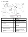
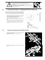
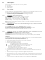
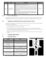
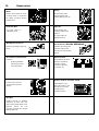
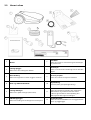
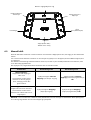
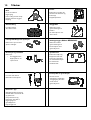
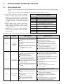
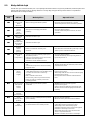
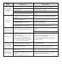
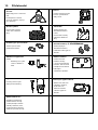
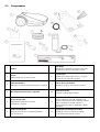
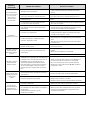
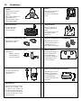
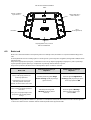
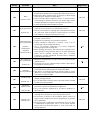
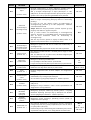
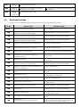
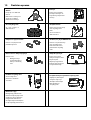
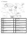
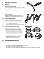
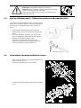
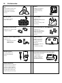
What's in the Box
2.3.
1
Unit
7
RoboRuler
Used for setting the distance of the Perimeter Wire
from the lawn edge
2
Wire Pegs
Used for securing the wire to the ground
8
Base Station
Used by the unit to dock and charge when it is not
mowing
3
Perimeter Wire
Used to create a virtual wall for your unit
9
Base Station Stakes
Used for securing the Base Station to the ground
4
Operating & Safety Manual
10
Extension Cable
15 meters (50 ft.), (Low voltage cable)
5
Wire Connectors
Used for splicing wires (as needed)
11
Power Box
Used to deactivate (halt) the automatic operation
mode and reactivate it as needed. Also provides
indication of the unit
’s
status (Docking or
Operating) and the Perimeter Wire’s health
6
Plot Connectors
Used for connecting the Perimeter Wire to the Base
Station
12
Power Box Mount
Used for fixing the Power Box to a wall (including
Screws and dowels)

3. Planning Ahead
Getting your lawn ready for the unit
is rather simple.
Still, as each lawn is unique, we recommend reading this chapter before starting to install the perimeter wire.
Planning the wire route and drawing a sketch of the lawn, including all obstacles and Base Station location, will
make it easier and will prevent mistakes during the setup.
Watch the unit’s
setup & operation video.
Also available on our
website.
Please complete reading this “Planning Ahead” chapter before you start the setup. It will guide you in finding
the best locations for the Base Station, Power Box, and for the Perimeter Wire.
The Perimeter Wire functions as an “invisible wall” for the unit. It sets the boundaries of lawn zones and it surrounds
specific areas where you do not want the unit
to enter. The Perimeter Wire is held to the ground with small pegs,
supplied with the unit. Soon after settling, the wire will become invisible under the growth of new grass.
As soon as the unit
starts operating, it turns on a signal that runs along the Perimeter Wire. This signal keeps the unit
within its working zones and away from preset demarcated areas.
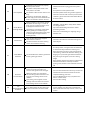
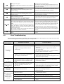
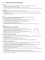
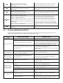
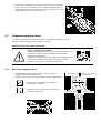
Lawn Types: What does your lawn look like?
3.1.
There are 3 basic types of lawns: Some lawns are combinations
of more than one type.
Your first task is to determine which type is yours.
Unit model without a Base Station, then your zones should
be defined as 'Separated Zone' (refer to Paragraph 3.2.3, 4.8
and 6.5)
o Main Zone Only
The unit will simply mow this lawn within its set
boundaries.
o Main Zone + Sub-Zone(s)
The unit will mow the Main Zone and will move
automatically to the Sub-Zone(s).
o Separated Zone
The unit will mow each zone separately. Its movement
between zones is restricted. Thus, you will have to bring
the mower from the Main Zone to the Separated Zone
every time you want to mow it.
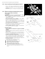
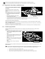
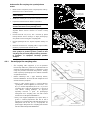
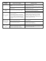
3.1.1.
« Main Zone Only » Type Lawn
The “Main Zone Only” lawn consists of one whole area. It has
no Sub- Zones and no Separated Zones.
If you answer “yes” to all of the following questions, your
lawn is a “Main Zone Only” type lawn:
o Is your grass area one continuous zone?
And:
o Are all areas of your lawn wide enough for the unit
to navigate through effectively? (Min. 3 meters (10
ft.) wide at its narrowest point).
Main Zone
Main Zone
Sub
-
Zone
Separated- Zone
Main Zone Only
At least 3 meters (10 ft.)
wide
Main Zone

If your lawn does not match this description, read the next Sections to find the style of your lawn.
If your lawn is “Main Zone Only”, you can skip to Section 3.3 of this chapter to determine the Base Station Location.
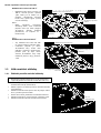
3.1.2. “Main Zone + Sub-Zone(s)“ Type Lawn
This type of lawn consists of more than one zone
and these zones are connected by a narrow pass.
In this type of lawn, the unit
will be able to drive
from one zone to the other in order to mow the
whole area.
If you answer “yes” to all of the following
questions, your lawn is a “Main Zone + Sub-Zone”
type lawn:
o Is your grass area one continuous area?
o Are parts of your lawn separated from the
Main Zone?
o Is there a Narrow Pass of at least 1m (3.3 ft.)
for the unit
to drive through between these zones?
o I
s this Narrow Pass firm, level and smooth (not stony, sandy or elevated)?
For example: grass area, sidewalk, firm path, solid ground.
Such additional areas are called Sub-Zones.
If your lawn contains a Sub-Zone as defined in this section, refer to Section 6.4.2 (Add Sub-Zone - number p022 in the
table).
Defining Sub-Zone(s) will enable the unit
to
drive through the Narrow Pass in order to get to a Sub-Zone and to mow
both the Main Zone and its Sub-Zone(s) one zone at a time.
If your lawn does not match this description, skip to the next Section 3.1.3 of this chapter: “Separate Zones”
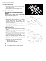
3.1.3. “Separated Zones” Type Lawn
“Separated Zones” type lawn consists of two or more zones that are not connected. The unit
cannot drive between
these zones.
If you answer “yes” to at least one of the following questions, your lawn is of the “Separated Zones” type.
o Are parts of your lawn separated by fences,
sidewalks, or other objects that the unit
cannot
pass?
Or
o Are parts of your lawn separated by a gravel
path or similar material that may damage the
mower blade?
Or
o Are the zones of your lawns joined by a pass too
narrow for the unit
to drive through: less than
1
m (3.3 ft.) in width?
Or
o Are the zones of your lawn situated at lower or
higher level?
If your lawn contains a Separated Zone as defined in this section, refer to Section 6.4.2 (Add Separated Zone - number
p014 in the table).
If your lawn does not fit any of these descriptions, it is probably either a “Main Zone Only” or “Main Zone + Sub-
Zone” type. Skip to Section 3.3 – Select Base Station and Power Box Location.
•
A lawn may consist of up to 2 Separated Zones
.
• The unit must be carried or driven to this area manually.
• Any of the 3 types can be a combination of more than one type of lawn.
Main Zone
Main Zone
Sub- Zone
Main + Sub-Zone with a Narrow pass
Separated
-
Zone
Main Zone
Main Zone
Separated
-
Zone

Types of Separated Zone
setups:
A Separated Zone smaller than
100
m²
(1100
ft²)
o Separated area that is smaller than
100m² (1100 ft²) can be covered in a
single operation, thus, if possible,
the separated area may be
connected to the main area’s
Perimeter Wire (have the signal
come from the Main Base Station).
Or
o It may need its own separate
Perimeter Wire. In that case, it will
have to be connected to a Perimeter
Switch (optional accessory – see
Chapter 12 - Accessories).
Or
A Separated Zone larger than 100 m² (1100 ft²)
o If a separated area is larger than
100m² (1100 ft²), then it requires
more than a single operation to
cover the area;
o In such cases, an additional Base
Station (optional accessory) should
be installed in the Separated Zone;
otherwise you will have to
manually bring the unit several
times to the Separated Zone in
order to complete the mowing of
the area.
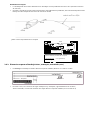
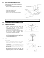
Select Base Station Location
3.2.1.
Base Station Location Guidelines
• Do not place the Base Station within 3 meters (10 ft.) after
a corner (relevant for Internal Setup only - section 3.2.2).
• The Base Station should be within 15m (50 ft.) of a power
outlet (230V / 120V).
• If the lawn has more than one zone, place the Base
Station within the largest zone.
• Make the Base Station invisible to the street to avoid
theft.
• Select a shady spot. This will extend battery lifetime.
• Place the Base Station on a relatively level ground. Do not
place it on a slope.
• Place the Base Station away from sprinkler heads.
Separated Zone Smaller than 100m
2
(1100ft
2
)
2 Wires under same peg
Base Station
Separated Zone larger than 100m
2
(1100ft
2
)
Optional Power Box & Base
Station
Main zone Power Box & Base
Station
Min. 3m (10ft )
from any corner

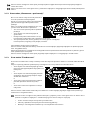
There are two options to set the Base Station:
3.2.2.
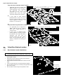
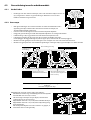
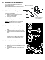
Internal Setup (on the lawn perimeter)
• Choose a place along the Perimeter Wire where you
want to place the Base Station, based on the inputs
given in paragraph 3.2.1.
• Place the Base Station in the direction shown in the
figure to the right.
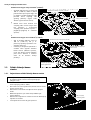
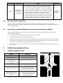
3.2.3.
External Setup (off the lawn perimeter):
There are two types of External Setup:
A. At a corner
In this type of setup, the Base Station is located at o
ne of
the corners of the lawn, as shown in the figure at the right.
•
Choose a corner where you want to place the Base
Station outside of the lawn area.
•
Place the Base Station, where its front side is touching
the lawn edge or placed somewhat on the lawn.
•
Continue to lay the perimeter wire as shown in the
figure to the right, where it continues at least 10cm (4”)
beyond the Base Station and turns back towards the
lawn at a distance of 10cm (4”) from the other wire.
•
The Base Station may be placed in a small shift to the
right in order to allow smooth entry of the unit to the
Base Station.
•
You will have the opportunity to later adjust the Base
Station position to confirm smooth entry.
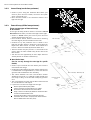
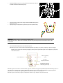
B. Outside the lawn
(Can be set only through the unit
App for specific
models)
• C
hoose a place outside the lawn where you want the
unit to dock and charge.
• Confirm the path between the lawn and the outside area
is smooth with no height difference, so the unit will not
get stuck and will follow the wire smoothly.
• The surface between the lawn and the Base Station
should be hard (such as a sidewalk or rigid ground) and
not sandy or stony, so the unit will not slip or get stuck
on it.
• The area between the lawn and the Base Station should
be clear of obstacles and objects.
• Lay the wire as shown in the figure to the right:
Narrow path of 50cm (20”) width.
Square Perimeter Island of 30cm (12”) edges.
Island starts 50cm from the Perimeter Wire.
Keep a distance of 10cm (4”) between Perimeter Wire
and the Island from both sides.
The front of the Base Station should be placed a
minimum distance of 1.5m (5 ft.) from the Perimeter
Wire and NOT more than 4m (13 ft.).
10cm (4’’)
10cm (4’’)
Min. 10cm (4’’)
Main Zone
Perimeter Island
30°cm
10cm (4’’)
50cm (20’’)
50cm (20’’)
Min. 1.50m (5ft) – Max 4m (13 ft)

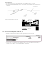
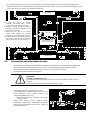
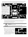
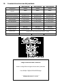
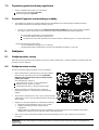
Select Power Box Location
3.3.
Consider the following in order to select the Power Box
location:
• The Power Box will be connected to the Base Station
using the 15m (50ft.) Extension Cable.
• Select a suitable location for the Power Box to be
mounted on a wall near a power outlet.
• Locate it outside the lawn perimeter.
• Select an easily accessed spot.
• Select a dry and sheltered location.
• The Power Box is to be mounted vertically.
The Power Box is suitable for Outdoor use. Yet, it should be placed in a sheltered, dry and well ventilated spot.
The Power Box should not be exposed to direct sunlight or rain.
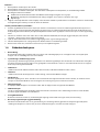
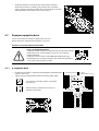
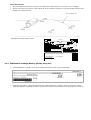
Planning the Perimeter Wire Layout
3.4.
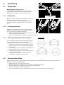
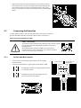
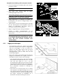
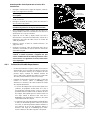
3.4.1.
Objects inside
lawn
• Objects such as flower beds, ponds, or small trees can
be protected by creating “Perimeter Islands”, which
are demarcated areas of the lawn, where the unit does
not enter.
• In the areas where obstacles are grouped closely
together, they should be demarcated by a single,
continuous Perimeter Island.
• Obstacles that are vertical, relatively rigid, and higher
than 15 cm (6 inches), such as trees, phone or power
poles, do not need Perimeter Island. The unit will turn
when it collides with these obstacles.
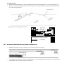
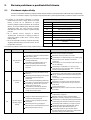
3.4.2. Slopes
Slope on the perimeter
• T
he Perimeter Wire can be laid across a slope that
slants less than 10% (10 cm rises per 1m).
CAUTION! If the Perimeter Wire is laid across a slope
steeper than 10%, there is a risk that the mower will
slip and cross outside the wire, especially when the
grass is wet'.
However, if there is a barrier (e.g. fence or wall) that
can protect the mower from slipping off, the Perimeter
Wire can be set on that slope.
Power Box fixed
to the wall
15m (50ft) Extension
Cable (low voltage)
Perimeter Slope
Max. 10%

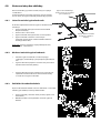
Slope inside the lawn
• The unit
can mow areas inside the working area with a slope of up to 35% (35cm rise per 1m).
• Tip: If the unit tilts off the ground while climbing a slope, it is too steep. Exclude this steep area from the unit’s
cutting area.
How to calculate the slope of your lawn?
3.4.3.
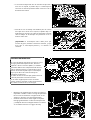
Distances from the Edge (Pools, Ponds, Cliffs, etc.)
• R
oboRuler is used to measure the distance from the edge, where the wire is to be placed.
• In certain cases, near bodies of water such as pools and ponds, or great height differences such as cliffs, it is
required to maintain a greater distance from the Edge (see Section 4.2.2).
In Lawn Slope 35%
100cm (3.3ft)
Length
35cm (1.1ft)
Max 35% slope
Evaluation
How to calculate the slope of your lawn?
35cm (Elevation)
100cm (Length)
= 35% (slope)

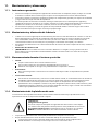
4. Initial Setup
Preparations
4.1.
Recommendations before you start:
During setup, you will insert pegs into the ground. To
complete this task smoothly, we recommend not to do it
while the grass is high and to water it before starting.
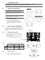
4.1.1.
Getting Ready
Make sure all parts needed for setup are within reach. Have
the unit box nearby, so all items are available.
In addition, you will need the following tools: A hammer,
small flat screwdriver, Phillips screwdriver, Combination
Pliers.
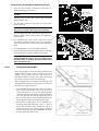
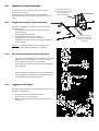
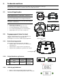
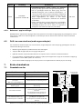
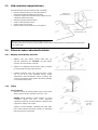
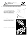
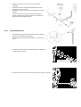
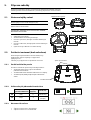
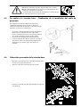
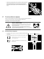
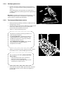
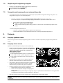
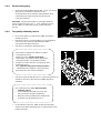
4.1.2.
Installing the Power Box
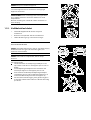
Mount the metal bracket onto a vertical surface with the
provided screws. Make sure the narrow part with the holes
facing up as shown in the figure to the right.
• Place the Power Box above the metal bracket and slide it
into place along the vertical surface.
• Connect the Power Box to a regular power outlet (230V / 120V).
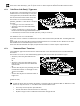
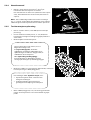
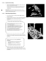
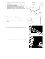
4.1.3.
Charging the battery before the first operation
You can charge the unit battery while running the setup of
the Perimeter Wire. This will ensure that the unit will be
ready for operation when the setup is completed.
• The power of the mower is switched off when shipped
from the factory. Switch on the Safety Switch to power
on the mower.
• Connect the DC Cable coming from the Power Box to the
Charging Socket at the rear side of the unit.
• Confirm the Battery LED on the unit is blinking, which is
an indication of charging.
• Leave the unit connected to the Power Box while
completing the setup of the Perimeter Wire.
P
erimeter Wire Setup
4.2.
Before you start the setup, you should have a plan for the Perimeter Wire layout and for the location of the Base Station.
Your plan should consider the following:
o What type of lawn areas does your lawn have?
(Main Zone Only / Main + Sub-Zones / Separated Zones / combination of types).
o Are there protected or excluded areas on the lawn? (Perimeter Islands).
o Are there any slopes that the unit should avoid?
o Are there edges of pools, ponds, and cliffs etc., which need an extra distance from the Perimeter Wire?
Safety Switch
Hammer
Combination Pliers
Small flat and Phillips
Screwdrivers

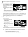
Starting Point: Perimeter Wire at the Base Station area.
• Place the Base Station, according to your plan, as
shown in the figure to the right.
! Do not place the Base Station within 3m (10 ft.) of
a corner.
• Select the roll of wire with a green plot connector
attached to the end.
• Pull the plot connector and some wire out of the
plastic covering.
! Do not remove the spool of wire from its covering.
The plastic covering is the dispenser for the wire.
• Peg the beginning of the wire to the ground, where
the Base Station will be located. Pegs are supplied in
the unit’s box.
• Pull out 30 cm (12 inches) of wire and leave it loose
near the Base Station location. Later, at the end of the
setup, this part of the wire will close the Perimeter Wire
loop.
• Start laying the wire in an anticlockwise direction.
• Continue to pull the Perimeter Wire out of its covering,
laying it loosely as you walk along the lawn edge.
! If you get to any area /object that needs care or
special boundaries, make sure you carefully lay the
Perimeter Wire as needed. The next sections deal
with such special cases.
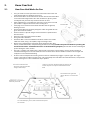
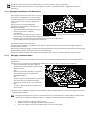
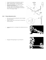
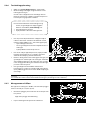
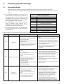
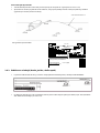
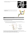
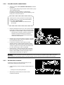
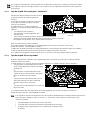
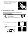
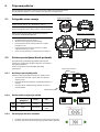
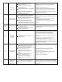
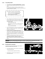
4.2.1.
Laying the Perimeter Wire
o The Perimeter Wire is secured to the ground by pegs
supplied with the unit. Initially insert pegs every few
meters and at corners. At this early stage set a
minimum number of pegs. Later, after testing the
wire setup, you will insert all necessary pegs.
o After uncoiling some wire, before inserting pegs, use
the RoboRuler to determine the distance of the wire
from the lawn edge or obstacles.
• If the working area borders with a flat area, a flower
bed, a small cliff (not more than 1 cm / 0.4”), or a
small stair (up to 5 cm / 2”), the Perimeter Wire
should be laid 20 cm (8 inches) inside the working
area. This prevents the wheels from driving into a
ditch. Use the shorter distance of the RoboRuler to
set the distance of the wire from the lawn edge.
• If the edge is sloped (max 10% is allowed) or is
bordered with high obstacles such as a wall or
fence, the Perimeter Wire should be laid at a
distance of 28 cm (11 inches) from the obstacle.
Use the longer distance of the RoboRuler to set the
distance of the wire from a wall.
Min. 3m (10ft )
from any corner
Perimeter Wire
Peg
28cm from Wall (11’’)

• If the working area borders against a flat path
that lies level with the lawn, it is possible to allow the
unit to run over the path. The Perimeter Wire should then
be laid 10 cm (4 inches) from the edge of the path.
• When the working area is divided by a flat path
that is level with the lawn, it is possible to allow the unit
to run over the path. The Perimeter Wire can be laid
under the pavement blocks or in the joint between
them.
Important! The mower must never run over gravel,
mulch, or similar material, which can cause the mower to
slip and damage the blade.
IMPORTANT INFORMATION
If the working area is adjacent to a swimming
pool, watercourse, slope greater than 10%,
precipice higher than 50cm (20 inches) or a
public road, the Perimeter Wire must be
supplemented with a fence or the like. The
height must then be at least 15cm (6 inches).
This will prevent the mower from ending up
outside the working area under any
circumstances.
If such a barrier exists, you may set the
Perimeter Wire 28cm (11 inches) from the
barrier.
If there is no fence or the like, then lay the
Perimeter Wire at minimum distance of 1.2m
from the water.
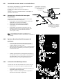
o Maintain a 45° angle in all left-turn corners when
laying the wire along the perimeter. It is not
necessary to maintain 45° angle on right-turn
corners along the perimeter.
o Continue laying the wire, according to your plan.
Gradually pull the wire out of its dispenser and lay it
loosely as you are moving in an anticlockwise
direction.
Min. 1.2m (4ft)
Min. 15cm (6’’)
Perimeter Wire
Right turns
Left turns

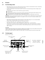
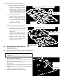
Perimeter Wire within the Working Area
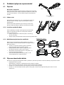
4.3.
4.3.1.
Hard Obstacles
o Obstacles that can withstand a collision, for example, trees or bushes higher
than 15 cm (6”), do not need to be demarcated by the Perimeter Wire. The unit
will turn when it collides with this type of obstacle.
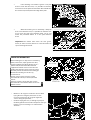
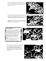
4.3.2.
Perimeter Islands
o Use the Perimeter Wire to demarcate areas inside the working area by creating
islands around obstacles that cannot withstand a collision, for example, flower
beds and fountains.
o Continue uncoiling the wire, moving from the edge towards the protected object.
o Peg the Perimeter Wire around the protected object in a clockwise direction.
o Complete bordering the island and return to the spot where you left the lawn’s edge
o The wires leading to the Island and from it should be parallel and touching.
Therefore, peg both wires, to and from the island, together with the same pegs.
o The unit will not recognize these two wires. It will mow over them as if they do not exist.
o The unit will recognize the single blocking wire around the Perimeter Island and will not enter this area.
CAUTION! Setting the Perimeter Wire anticlockwise around the obstacle
will cause the unit to drive into the island
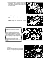
Keep the following distances when setting Perimeter Islands:
The minimum distance of the Perimeter Wire from the
protected area should be 28 cm (11 inches).
If you need to protect a thin object, set the minimum radius
of the Island to 35 cm (15 inches).
Maintain a minimum of 1m (3.3 ft.) between adjacent islands.
Maintain a minimum of 1m (3.3 ft.) between island wire and
the Perimeter Wire.
If protected objects are grouped closely together, demarcate
them as a single Perimeter Island.
2 Wires under same
peg
Perimeter Wire Position
Perimeter Wire
Direction of setup:
Clockwise around obstacle
Min. distance between islands:
1m (3.3ft). Otherwise,
demarcate jointly as one island

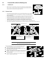
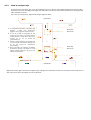
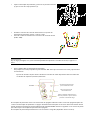
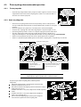
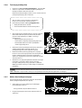
4.3.3. Setting a Narrow Pass
A Narrow Pass is defined as a path that connects two zones of the lawn. The path enables the unit to drive between
the zones while following the wire, but prevents the unit from crossing between them while mowing the inner area of
the zones.
To set up a Narrow Pass follows the instructions given in the figure below:
The above setup allows the unit to drive along the wire to reach the Sub-Zone. However, while mowing each zone
individually, it will not cross over to the other zone.
A. At the point you want the unit to start
driving towards the Sub-Zone start to set
the Narrow Pass.
B. 50 cm (20 inches) from the Narrow Pass
entry, set a Perimeter Island (refer to 4.2.4)
of 30 cm sides (12 inches) at a distance of 10
cm (4 inches) from the Perimeter Wire.
C. Continue to lay the wire towards the Sub-
Zone and lay another Island with the same
dimensions, 50 cm (20 inches) from the
Sub-Zone Perimeter Wire.
D. After completing the setup of the wire in
the Sub-Zone, make sure you keep 10 cm (4
inches) between the wire and the islands on
the way back to the Main Zone.
Sub-Zone
Perimeter Island
30x30c
Perimeter Island
30x30c
Main
Zone

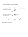
If the Narrow Pass is wider than 2m (6.5ft.), and you want the unit to mow the area inside the Narrow Pass, then you can set
the wire as shown in the figure below. Such a setup allows the mower to mow inside the Narrow Pass while mowing the
inner part of the lawn, but prevents it from crossing between the zones.
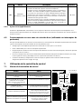
Fastening Perimeter Wire to the Ground
4.4.
o Before starting to lay the Perimeter Wire, it is recommended to cut the grass where the wire is to be laid. It will
then be easier to attach the wire to the ground. The risk that the mower will damage the wire during the
operation is reduced.
o It is not necessary to bury the Perimeter Wire, though you may do so, up to 5 cm (2 inches) deep.
o Pull the wire tight while hammering the peg all the way into the ground.
WARNING!
Protect your eyes! Protect your hands!
Use proper eye protection and wear appropriate work gloves when hammering the pegs.
Hard or dry ground may cause pegs to break when driving them in.
o Use a hammer to insert the pegs into the ground.
o Insert the pegs at distances that will keep the wire
down below the grass level and prevent the wire from
becoming a tripping hazard (approximately 75 cm /
30” between pegs).
• The wire and the pegs will gradually
become invisible under the growth of new grass.
o If an additional wire is required in order to complete
the setup, connect it using the water-proof wire
connectors supplied with the unit. (See Section 11.4 –
Splicing the Perimeter Wire).
A. At the point you want the mower to start
driving towards the Sub-Zone start to set
the Narrow Pass.
B. Set an Island at the middle of the Narrow
Pass and keep a distance of 10 cm (4”)
from the Perimeter Wire.
C. The island dimensions should be 30 cm
(12”) along the side and as wide as
needed, keeping 10 cm (4”) from both
sides.
D. After completing the setup of the wire in
the Sub-Zone, make sure you keep 10 cm
(4”) between the wire and the island on
the way back to the Main Zone.
Sub-Zone
Perimeter
Island
Main
-
Zone
Main
-
Zone
As long as needed when
keeping 10cm from both
sides

Use only the wire connectors supplied with the unit.
Neither Twisted cables, nor a screw terminal insulated with
insulation tape are a satisfactory splice.
Soil moisture will cause the conductors to oxidize, which will later
cause a broken circuit.
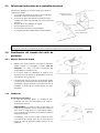
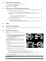
Back at the Base Station – Completing the Perimeter Wire Setup
4.5.
Once the Perimeter Wire loop is completed and pegged to
the ground, complete the setup by attaching the beginning
and the end of the Perimeter Wire to the Base Station Head.
o Peg the two Perimeter Wires down to the ground using
the same peg leaving enough loose wire.
o Trim the end without the connector to make both of
equal length and twist the two wires.
o Strip back 5 mm (1/4 inches) of insulation from the wire
end.
o Insert the end of the wire without the connector into
the hole of the connector. Use a small flat screwdriver
to tighten and secure this wire into the connector.
Placement and connection of the Base Station
4.6.
o Place the Base Station on the Perimeter Wire as shown in
the figure to the right.
o Align the center of the Base Station on the wire.
o Attach the Perimeter Wire connector to the Base Station
Head.
Small flat screwdriver
Page is loading ...
Page is loading ...
Page is loading ...
Page is loading ...
Page is loading ...
Page is loading ...
Page is loading ...
Page is loading ...
Page is loading ...
Page is loading ...
Page is loading ...
Page is loading ...
Page is loading ...
Page is loading ...
Page is loading ...
Page is loading ...
Page is loading ...
Page is loading ...
Page is loading ...
Page is loading ...
Page is loading ...
Page is loading ...
Page is loading ...
Page is loading ...
Page is loading ...
Page is loading ...
Page is loading ...
Page is loading ...
Page is loading ...
Page is loading ...
Page is loading ...
Page is loading ...
Page is loading ...
Page is loading ...
Page is loading ...
Page is loading ...
Page is loading ...
Page is loading ...
Page is loading ...
Page is loading ...
Page is loading ...
Page is loading ...
Page is loading ...
Page is loading ...
Page is loading ...
Page is loading ...
Page is loading ...
Page is loading ...
Page is loading ...
Page is loading ...
Page is loading ...
Page is loading ...
Page is loading ...
Page is loading ...
Page is loading ...
Page is loading ...
Page is loading ...
Page is loading ...
Page is loading ...
Page is loading ...
Page is loading ...
Page is loading ...
Page is loading ...
Page is loading ...
Page is loading ...
Page is loading ...
Page is loading ...
Page is loading ...
Page is loading ...
Page is loading ...
Page is loading ...
Page is loading ...
Page is loading ...
Page is loading ...
Page is loading ...
Page is loading ...
Page is loading ...
Page is loading ...
Page is loading ...
Page is loading ...
Page is loading ...
Page is loading ...
Page is loading ...
Page is loading ...
Page is loading ...
Page is loading ...
Page is loading ...
Page is loading ...
Page is loading ...
Page is loading ...
Page is loading ...
Page is loading ...
Page is loading ...
Page is loading ...
Page is loading ...
Page is loading ...
Page is loading ...
Page is loading ...
Page is loading ...
Page is loading ...
Page is loading ...
Page is loading ...
Page is loading ...
Page is loading ...
Page is loading ...
Page is loading ...
Page is loading ...
Page is loading ...
Page is loading ...
Page is loading ...
Page is loading ...
Page is loading ...
Page is loading ...
Page is loading ...
Page is loading ...
Page is loading ...
Page is loading ...
Page is loading ...
Page is loading ...
Page is loading ...
Page is loading ...
Page is loading ...
Page is loading ...
Page is loading ...
Page is loading ...
Page is loading ...
Page is loading ...
Page is loading ...
Page is loading ...
Page is loading ...
Page is loading ...
Page is loading ...
Page is loading ...
Page is loading ...
Page is loading ...
Page is loading ...
Page is loading ...
Page is loading ...
Page is loading ...
Page is loading ...
Page is loading ...
Page is loading ...
Page is loading ...
Page is loading ...
Page is loading ...
Page is loading ...
Page is loading ...
Page is loading ...
Page is loading ...
Page is loading ...
Page is loading ...
Page is loading ...
Page is loading ...
Page is loading ...
Page is loading ...
Page is loading ...
Page is loading ...
Page is loading ...
Page is loading ...
Page is loading ...
Page is loading ...
Page is loading ...
Page is loading ...
Page is loading ...
Page is loading ...
Page is loading ...
Page is loading ...
Page is loading ...
Page is loading ...
Page is loading ...
Page is loading ...
Page is loading ...
Page is loading ...
Page is loading ...
Page is loading ...
Page is loading ...
Page is loading ...
Page is loading ...
Page is loading ...
Page is loading ...
Page is loading ...
Page is loading ...
Page is loading ...
Page is loading ...
Page is loading ...
Page is loading ...
Page is loading ...
Page is loading ...
Page is loading ...
Page is loading ...
Page is loading ...
Page is loading ...
Page is loading ...
Page is loading ...
Page is loading ...
Page is loading ...
Page is loading ...
Page is loading ...
Page is loading ...
Page is loading ...
Page is loading ...
Page is loading ...
Page is loading ...
Page is loading ...
Page is loading ...
Page is loading ...
Page is loading ...
Page is loading ...
Page is loading ...
Page is loading ...
Page is loading ...
Page is loading ...
Page is loading ...
Page is loading ...
Page is loading ...
Page is loading ...
Page is loading ...
Page is loading ...
Page is loading ...
Page is loading ...
Page is loading ...
Page is loading ...
Page is loading ...
Page is loading ...
Page is loading ...
Page is loading ...
Page is loading ...
Page is loading ...
Page is loading ...
Page is loading ...
Page is loading ...
Page is loading ...
Page is loading ...
Page is loading ...
Page is loading ...
Page is loading ...
Page is loading ...
Page is loading ...
Page is loading ...
Page is loading ...
Page is loading ...
Page is loading ...
Page is loading ...
Page is loading ...
Page is loading ...
Page is loading ...
Page is loading ...
Page is loading ...
Page is loading ...
Page is loading ...
Page is loading ...
Page is loading ...
Page is loading ...
Page is loading ...
Page is loading ...
Page is loading ...
Page is loading ...
Page is loading ...
Page is loading ...
Page is loading ...
Page is loading ...
Page is loading ...
Page is loading ...
Page is loading ...
Page is loading ...
Page is loading ...
Page is loading ...
Page is loading ...
Page is loading ...
Page is loading ...
Page is loading ...
Page is loading ...
Page is loading ...
Page is loading ...
Page is loading ...
Page is loading ...
Page is loading ...
Page is loading ...
Page is loading ...
Page is loading ...
Page is loading ...
Page is loading ...
Page is loading ...
Page is loading ...
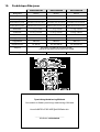
-
 1
1
-
 2
2
-
 3
3
-
 4
4
-
 5
5
-
 6
6
-
 7
7
-
 8
8
-
 9
9
-
 10
10
-
 11
11
-
 12
12
-
 13
13
-
 14
14
-
 15
15
-
 16
16
-
 17
17
-
 18
18
-
 19
19
-
 20
20
-
 21
21
-
 22
22
-
 23
23
-
 24
24
-
 25
25
-
 26
26
-
 27
27
-
 28
28
-
 29
29
-
 30
30
-
 31
31
-
 32
32
-
 33
33
-
 34
34
-
 35
35
-
 36
36
-
 37
37
-
 38
38
-
 39
39
-
 40
40
-
 41
41
-
 42
42
-
 43
43
-
 44
44
-
 45
45
-
 46
46
-
 47
47
-
 48
48
-
 49
49
-
 50
50
-
 51
51
-
 52
52
-
 53
53
-
 54
54
-
 55
55
-
 56
56
-
 57
57
-
 58
58
-
 59
59
-
 60
60
-
 61
61
-
 62
62
-
 63
63
-
 64
64
-
 65
65
-
 66
66
-
 67
67
-
 68
68
-
 69
69
-
 70
70
-
 71
71
-
 72
72
-
 73
73
-
 74
74
-
 75
75
-
 76
76
-
 77
77
-
 78
78
-
 79
79
-
 80
80
-
 81
81
-
 82
82
-
 83
83
-
 84
84
-
 85
85
-
 86
86
-
 87
87
-
 88
88
-
 89
89
-
 90
90
-
 91
91
-
 92
92
-
 93
93
-
 94
94
-
 95
95
-
 96
96
-
 97
97
-
 98
98
-
 99
99
-
 100
100
-
 101
101
-
 102
102
-
 103
103
-
 104
104
-
 105
105
-
 106
106
-
 107
107
-
 108
108
-
 109
109
-
 110
110
-
 111
111
-
 112
112
-
 113
113
-
 114
114
-
 115
115
-
 116
116
-
 117
117
-
 118
118
-
 119
119
-
 120
120
-
 121
121
-
 122
122
-
 123
123
-
 124
124
-
 125
125
-
 126
126
-
 127
127
-
 128
128
-
 129
129
-
 130
130
-
 131
131
-
 132
132
-
 133
133
-
 134
134
-
 135
135
-
 136
136
-
 137
137
-
 138
138
-
 139
139
-
 140
140
-
 141
141
-
 142
142
-
 143
143
-
 144
144
-
 145
145
-
 146
146
-
 147
147
-
 148
148
-
 149
149
-
 150
150
-
 151
151
-
 152
152
-
 153
153
-
 154
154
-
 155
155
-
 156
156
-
 157
157
-
 158
158
-
 159
159
-
 160
160
-
 161
161
-
 162
162
-
 163
163
-
 164
164
-
 165
165
-
 166
166
-
 167
167
-
 168
168
-
 169
169
-
 170
170
-
 171
171
-
 172
172
-
 173
173
-
 174
174
-
 175
175
-
 176
176
-
 177
177
-
 178
178
-
 179
179
-
 180
180
-
 181
181
-
 182
182
-
 183
183
-
 184
184
-
 185
185
-
 186
186
-
 187
187
-
 188
188
-
 189
189
-
 190
190
-
 191
191
-
 192
192
-
 193
193
-
 194
194
-
 195
195
-
 196
196
-
 197
197
-
 198
198
-
 199
199
-
 200
200
-
 201
201
-
 202
202
-
 203
203
-
 204
204
-
 205
205
-
 206
206
-
 207
207
-
 208
208
-
 209
209
-
 210
210
-
 211
211
-
 212
212
-
 213
213
-
 214
214
-
 215
215
-
 216
216
-
 217
217
-
 218
218
-
 219
219
-
 220
220
-
 221
221
-
 222
222
-
 223
223
-
 224
224
-
 225
225
-
 226
226
-
 227
227
-
 228
228
-
 229
229
-
 230
230
-
 231
231
-
 232
232
-
 233
233
-
 234
234
-
 235
235
-
 236
236
-
 237
237
-
 238
238
-
 239
239
-
 240
240
-
 241
241
-
 242
242
-
 243
243
-
 244
244
-
 245
245
-
 246
246
-
 247
247
-
 248
248
-
 249
249
-
 250
250
-
 251
251
-
 252
252
-
 253
253
-
 254
254
-
 255
255
-
 256
256
-
 257
257
-
 258
258
-
 259
259
-
 260
260
-
 261
261
-
 262
262
-
 263
263
-
 264
264
-
 265
265
-
 266
266
-
 267
267
-
 268
268
-
 269
269
-
 270
270
-
 271
271
-
 272
272
-
 273
273
-
 274
274
-
 275
275
-
 276
276
-
 277
277
-
 278
278
-
 279
279
-
 280
280
-
 281
281
-
 282
282
-
 283
283
-
 284
284
-
 285
285
-
 286
286
-
 287
287
-
 288
288
-
 289
289
-
 290
290
-
 291
291
-
 292
292
-
 293
293
-
 294
294
-
 295
295
-
 296
296
-
 297
297
-
 298
298
-
 299
299
-
 300
300
-
 301
301
-
 302
302
-
 303
303
-
 304
304
-
 305
305
-
 306
306
-
 307
307


Wolf Garten Robo Scooter 400 Original Operating Instructions
- Category
- Lawnmowers
- Type
- Original Operating Instructions
Ask a question and I''ll find the answer in the document
Finding information in a document is now easier with AI
in other languages
- español: Wolf Garten Robo Scooter 400
- slovenčina: Wolf Garten Robo Scooter 400
- čeština: Wolf Garten Robo Scooter 400
Related papers
-
Wolf Garten Robo Scooter 500 Original Operating Instructions
-
-
-
-
-
WOLF-Garten Esprit 46 BA Owner's manual
-
-
-
-
Other documents
-
Robomow RC306 (Up to 1/8 Acre) FAQ
-
Gardena Hattrick User manual
-
-
Robomow MC150 Owner's manual
-
STIHL RMI 632 User manual
-
Robomow RC304u User manual
-
Viking MI 422 Owner's manual
-
 Yard Force SC600ECO Original Instruction
-
-
Zipper ZI-RMR 2600 Operating instructions
