Craftsman 917.293650 Owner's manual
- Category
- Mini tillers
- Type
- Owner's manual
This manual is also suitable for

Caution:
Read and follow
all Safety Rules
and instructions
Before Operating
This Equipment
©
®
6.0 HP
17 iNCH TINE WIDTH
TU TULLERWiTH
COUNTER F_OTATI TIN
®Assembly
- Operation
Customer Responsibilities
oService and Adjustments
, Repa_r Parts
i iii ,, i i i ................................. i ,1111,1,,111,,111111,,i,i
Sears, Roebuck and Co., Hoffman Estates, IL 60179 U.S.A.
i, ii ,, iii

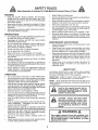
SAFETY RULES
Safe Operation Practices for Walk-Behind Powered Rotary Tillers
TRAINING
, Read the Owner's Manual carefulty_ Be thoroughly
familiar with the controls and the proper use of the
equipment. Know how to stop the unit and disengage
the controls quickly
• Never allow children to operate the equipment.. Never
allow adutts to operate the equipment without proper
instruction
• Keep the area of operation clear of all persons, particu-
larly small children, and pets.
PREPARATION
• Thoroughly inspect the area where the equipment is to
be used and remove all foreign objects°
• Disengage all clutches and shift into neutral before
starting the engine (motor).
• Do not operate the equipment without wearing ad-
equate outer garments.r Wear footwear that will im-
prove footing on slippery surfaces°
• Handle fuel with care; it is highly flammable
• Use an approved fuel container.
. Never add fuel to a running engine or hot engine
. Fill fuel tank outdoors with extreme care. Never fi!Ifuel
tank indoors.
- Replace gasoline cap securely and ciean up spilled
fuel before restarting.
o Use extension cords and receptacles as specified by
the manufacturer for all units with electric drive motors
or electric starting motors.
• Never attempt to make any adjustments while the
engine (motor) is running (except where specifically
recommended by manufacturer).
OPERATION
o Do not put hands or feet near or under rotating parts.
= Exercise extreme caution when operating on or cross-
inggravel drives, walks, or roads, Stay alert for hidden
hazards or traffic, Do not carry passengers.
- After striking a foreign object, stop the engine (motor),
remove the wire from the spark plug, thoroughly in-
spect the tiller for any damage, and repair the damage
before restarting and operating the tiller
° Exercise caution to avoid slipping or falling
• If the unit should start to vibrate abnormally, stop the
engine (motor) and check immediately for the cause
Vibration is generally a warning of trouble
• Stop the engine (motor) when leaving the operating
position,
o Take all possible precautions when leaving the ma-
chine unattended. Disengage the tines, shift into
neutral, and stop the engine.
° Before cleaning, repairing, or inspecting, shut off the
engine and make certain all moving parts have stopped.
Disconnect the spark plug wire, and keep the wire
away from the plug to prevent accidental starting,
Disconnect the cord on electric motors.
. Do not run the engine indoors; exhaust fumes are
dangerous,
. Never operate the tiller without proper guards, plates,
or other safety protective devices in place,
= Keep children and pets away
• Do not overload the machine capacity by attempting to
till too deep at too fast a rate.
• Never operate the maclqine at high speeds on slippery
surfaces. Look behind and use care when backing.
• Never allow bystanders near the unit
o Use only attachments and accessories approved by
the manufacturer of the tiller (such as wheel weights,
counterweights, cabs, and the like).
. Never operate the tiller without good visibility or light
• Be careful when tilling in hard ground. The tines may
catch inthe ground and propel the tiller forward, If this
occurs, tet go of the handlebars and do not restrain the
machine
MAINTENANCE AND STORAGE
° Keep machine, attachments, and accessories in safe
working condition.
- Check shear pins, engine mounting bolts, and other
bolts at frequent intervals for proper tightness to be
sure the equipment is in safe working condition.
Never store the machine with fuel inthe fuel tank inside
a building where ignition sources are present, such as
hot water and space heaters, clothes dryers, and the
like. Allow the engine to cool before storing in any
enclosure.
o Atways refer to the operator's guide instructions for
important details if the tiller is to be stored for an
extended period.
- IMPORTANT-
CAUTIONS, IMPORTANTS, AND NOTES ARE A MEANS
OF ATTRACTING ATTENTION TO IMPORTANT OR
CRITICAL INFORMATION IN THIS MANUAL
IMPORTANT: USED TO ALERT YOU THAT THERE ISA
POSSIBILITY OF DAMAGING THIS EQUIPMENT.
NOTE: Gives essential information that witl aid you to
better understand, incorporate, or execute a particular set
of instructions,.
i, ,,Ul i , i , lu ,,UllllUr,_l ......
t ,_ Look for this symbol to point out im-
I _ portant safety precautions. It means
I _ CAUTION!!! BECOMEALERT!!! YOUR
SAFETY IS INVOLVED
I , u , i ii u i, i,i1_1i,Ulllllll
,,,, ,,,,,,,,,,,,,,,,,,,,,,,
CAUTION: Always disconnect spark
plug wire and place wire where it can-
not contact spark plug in order to pre-
vent accidental starting when setting
up, transporting, adjusting or making
repairs.
i,UUlll ii, i ,,Ul,i,
WARNING ...........
The engine exhaust from this product con-
tains chemicals known to the State of .Califor-
nia to cause cancer, birth defects, or other
reproductive harm.
u, i ilur Ullll,, iii ...... i,, ii,u,,

CONGRATULATIONS on your purchase of a Sears Tiller,
It has been designed, engineered and manufactured to
give you the best possible dependability and performance.
Should you experience any problems you cannot easily
remedy, pfease contact your' nearest authorized Sears
Service Center/Department. They have competent, welF
trained technicians and the proper tools to service or repair
this unit.
PIease read and retain this manual The instructions will
enable you to assemble and maintain your tiller' propedy
Always observe the "SAFETY RULES",
MODEL
NUMBER 917.293650
SERIAL
NUMBER
DATE OF
PURCHASE
THE MODEL AND SERIAL NUMBERS WILL BE
FOUND ON THE MODEL PLATE ATTACHED TO
THE TOP OF THE TRANSMISSION,
YOU SHOULD RECORD BOTHSERIALNUMBER
AND DATE OF PURCHASE AND KEEPIN A SAFE
PLACE FOR FUTURE REFERENCE.
PRODUCT SPECIFICATIONS
HORSEPOWER: 6,0 HP
DISPLACEMENT: 11.88 cu_ino(195cc)
GASOLINE CAPACITY: 4 Quarts
Unleaded Regular
I
i OIL (API-SF/SG) : SAE 30 (Above 32°F)
(CAPACITY: 20 oz.) SAE 5W-30 (Befow 32°F)
SPARK PLUG :
(GAP: 030")
Champion
RN4C
MAINTENANCE AGREEMENT
A Sears Maintenance Agreement isavailable on this prod-
uct. Contact your nearest Sears store for details.
CUSTOMER RESPONSIBILITIES
° Read and observe the safety rules.
o Follow a regular schedule in maintaining, caring for and
using your tiller.
o Follow the instructions under the "Customer
Responsibilities" and "Storage" sections ofthis Owner's
Manual..
IMPORTANT: THIS UNIT IS EQUIPPED WITH AN INTERNAL COMBUSTION ENGINE AND SHOULD t_OT BE USED ON
OR NEAR ANY UNIMPROVED FOREST-COVERED, BRUSH-COVERED OR GRASS COVERED LAND UNLESS THE
ENGINE'S EXHAUST SYSTEM IS EQUIPPED WITH A SPARK ARRESTER MEETING APPLICABLE LOCAL OR STATE
LAWS (IF ANY)._ IF A SPARK ARRESTER IS USED, tT SHOULD BE MAINTAINED IN EFFECTIVE WORKING ORDER BY
THE OPERATOR
IN THE STATE OF CALIFORNIA THE ABOVE IS REQUIRED BY LAW (SECTION _4442 OF THE CALIFORNIA PUBLIC
RESOURCES CODE). OTHER STATES MAY HAVE SIMILARLAWS_ FEDERAL LAWS APPLY ON FEDERAL LANDS+
SEE YOUR SEARS AUTHORIZED SERVICE CENTER/DEPARTMENT FOR SPARK ARRESTER. REFER TO THE REPAIR
PARTS SECTION OF THIS MANUAL FOR PART NUMBER.
LIMITED TWO YEAR WARRANTY ON CRAFTSMAN TILLER
For two years from date of purchase, when this Craftsman Ti_ler is maintained, lubricated, and tuned up according to
the operating and maintenance instructions in the owner's manual, Sears will repair free of charge any defect in
material or workmanship.
This W&rranty does not cover:
o Expendable items which become wom during normal use, such as tines, spark plugs, air cleaners and belt&
° Repairs necessary because of operator abuse or negligence, including bent crankshafts and the failure to
maintain the equipment according to the instructions contained in the owneCs manual.
o If this Craftsman Tiller is used for commercial or rental purposes, this Warranty applies for only 30 days from the
date of purchase.
WARRANTY SERVICE IS AVAILABLE BY RETURNING THE CRAFTSMAN TILLER TO THE NEAREST SEARS
SERVlCE CENTER/DEPARTMENT IN THE UNITED STATE& THIS WARRANTY APPLIES ONLY WHILE THIS
PRODUCT IS IN USE IN THE UNITED STATES.
This Warranty gives you specific legal rights, and you may also have other rightswhich vary from state to state.
SEARS, ROEBUCK AND CO. D/817 WA, HOFFMAN ESTATES, ILLINOIS 60179
3

i, u nl ,,in,nl lun , i
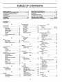
TABLE OF CONTENTS
'll'n"lllHirll' i i i 'u nllu Ull'UlU''' i' i
SAFETY RULES ............................................................ 2
CUSTOMER RESPONSIBILITIES ...................... 3,13-15
PRODUCT SPECIFICATIONS ...................................... 3
WARRANTY ................................................................... 3
ACCESSORIES ............................................................. 5
ASSEMBLY ................................................................ 6-8
OPERATION ................ ;......;..................................... 9-12
MAINTENANCE SCHEDULE ...................................... 13
SERVICE & ADJUSTMENTS ................................. 15-18
STORAGE ................................................................... 19
TROUBLESHOOTING ................................................. 20
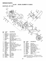
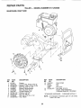
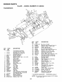
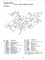
REPAIR PARTS-TILLER ........................................ 21-27
REPAIR PARTS-ENGINE ...................................... 28-33
SERVICEIPARTS ORDERING ................ BACK COVER
UNDEX
A
Accessories ........................................... 5
Adjustments:
Carburetor .....................................18
Depth Stake .................................10
Handle Height ...............................15
Side Shields ..................................11
Throttle .........................................18
Tines ............................................ 17
V-Belt (Ground Drive) .............. 16
Air Cleaner ....................................... 14
B
Belt:
Belt Guard .................................. 16
Repair Parts ............................. 22
V-Belt (Ground Drive) ............. 16
C
Cooling System ................................. 14
Controls:
Choke ...............................................9
Throttle .......................................... 9
Drive (Tines) ................................ 9
Cultivating ............................................12
Customer Responsibilities:
Air Cleaner .......................................14
Cooling System .............................14
Finish ..............................................15
Maintenance Schedule ............ 13
Muffler ............................................ 15
Oil Change .................................. 14
Spark Plug ................................. 15
Tines ................................................17
Transmission ...............................15
WBelt (Ground Drive) ............... 16
D
Depth Stake:
Adjustment ..............:......................t0
Repair Parts ...................................25
E
Engine:
Air Cleaner ................................. 14
Cooling System ........................ 14
FuelType ......................................11
Engine (conrd)
Lubrication ................................ 14
Oil Level .........................................11
Oil Type .....................................11,14
Spark Plug ......................................15
Starting .............................................12
Stopping ..........................................10
Storage .................................................19
Winter Operation ........................14
Fuel:
Filling Tank ...... .................................. t 1
Storage ............................................19
Type ............................................ 11
Finish:
Maintenance ........................................15
H
Handle:
Height Adjustment .....................15
Repair Parts .................................21
L
Lubrication:
Lubrication Chart ...................13
Engine .........................................14
Muffler:
Maintenance ................................15
Spark Arrester ...............................3
O
Oil:
Level .............................................11
Type .......................................... 11,14
Operation:
Cultivating .....................................12
Fill Fuel Tank ....................................1!
Starting Engine ...........................12
Stopping Tines & Engine ...........10
Tilling ...............................................10
Tilling Hints ..................................12
Tine Operation .......................... 10
Transporting Tiller ...................... 11
Winter Operation ........................14
R
Repair Parts:
Tiller .......................................................2!-27
Engine .........................................28-33
Rules for Safe Operation .................. 2
S
Service & Adjustments:
Carburetor .......................................18
Handle Height ...................................I5
Side Shields ....................................11
Throttle ..........................................t8
Tines ...............................................17
V-Belt (Ground Drive) ............... t6
Wheels .............................................15
Service:
Repair Parts ...................................21-33
Service Record ............................13
Shear Pins:
Operation ...................................12
Repair Parts ................................26
Spark Plug:
Gap ............................................. 3
Maintenance ........................... 15
Storage:
Fue! System ............................... 19
Tiller ........................................... 19
Tilling ...................................................10,12
Tines:
Arrangement/Replacement ..... 17
Operation .................................. 10
Repair Parts .................................26
Shear Pins ..........................................12
Transmission:
Maintenance ................................15
Repair Parts ................................24
Troubleshooting .................................20
Transporting ...........................................11
W
Warranty .....................................................3
Wheels:
Removal ................................... 15
Repair Parts ..............................23
4

.......................................... i,, 'IMIIIIIIIII
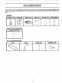
ACCESSORIES
ii ii, i ii '111,iii, ,111.................... i i i
These accessories were available when the tiller was purchased. They are also available at most Sears Retail outlets
and Service Centers. Most Sears Stores can order repair parts for you when you provide the model number of your
tiller=
ENGINE
SPARK PLUG
, ,, ,, H,, ,,,,,_,_,,,
MUFFLER
r,,,
AIR FILTER GAS CAN
ENG'i'NE"'O'iL STABILIZER
TILLER PERFORMANCE
,, ,,,
_,r,T,,
FURROW OPENER
L '',,' "
TILLER MAINTENANCE
TINES SHEAR PIN HAIRPIN CLIP
BELT
, ,,,,.,,,,,
0
5

i ii iii ii i ii
BLY
i ii ............................................................
Your new flier has been assembled at the factory with exception of those parts left unassembled for shipping purposes To
ensure safe and proper operation of your tiller all parts and hardware you assemble must be tightened securely Use the
correct tools as necessary to insure proper tightness
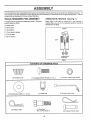
TOOLS REQUIRED FOR ASSEMBLY OPERATOR'S POSITION (See Fig. 1)
A socket wrench set will make assembly easier Standard When right or left hand is mentioned in this manual, it
wrench sizes are listed_
(1) Utility knife
(1) Wire cutter
(1) Screwdriver
(1) Tire pressure gauge
(t) Pair of pliers
(1) 9/16" wrench
means when you are in the operating position (standing
behind tiller handles)°
FRONT
LEFT RIGHT
OPERATOR'S
POSITION
FIG. 1
CONTENTS OF HARDWARE PACK
........................... ,, ,,,,,,,,,,,,,
L_ ,i,
(2) Handle Locks
,,,, ii,,111
(1) Flat Washer 13t32 x I x 11 Ga,
i i, i iii
(2) Hairpin Clips
(1) Carriage Bolt 3/8-16 UNC x I Gr 5
i IIIIIIIH i iiiiiiiir.........
(1) Cable Clip
ii i iiiii
(1) Pivot Bolt
3/8-16 UNC Grade 5
G
(1) Center Locknut 3/8-16 UNC
(1) Handle Lock Lever
Extra Shear Pins & Ciips
6

,,11,,,,,i,............... i, , , ,........ 1,1,1 L'L_
ASSEMBLY
..................... i, , i ,,,i,i1,,,,,i,i, ,i,i1,,,,,i,,,i,ii, ii, , i , ,
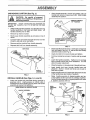
UNPACKING CARTON (See Fig, 2) o Grasp handle assembly, HoIdin"up"position. Besure
handle lock remains in gearcase notch, Slide handle
assembly into position,,
IMPORTANT; WHEN UNPACKING AND ASSEMBLING
TILLER, BE CAREFUL NOT TO STRETCH OR KINK
CABLES,,
, While holding handle assembly, cutcabletiessecuring
handle assembly to top frame and depth stake_ Let
handle assembly rest on tiller,
o Remove top frame of carton°
• Slowly ease handle assembly up and place on top of
carton,
o Cut down right hand front and right hand rear'corners
of carton, lay side carton wall down.
• Remove packing material from handle assembly°
• Separate shift rod from handle assembly,
SHIFT ROD
HANDLE
ASSEMBLY
FIG. 2
INSTALL HANDLE (See Figs. 3, 4, and 5)
o Insert one handle lock (with teeth facing outward) in
gearcase notch_ (Apply grease on smooth side of
handl_ lock to aid in keeping lock in place until handle
assembly is lowered into position.)
VIEW FROM R,H. SIDE OF TILLER
\ HANDLE ASSEMBLY
GEARCASE
NOTCH
HANDLE
LOCK
,_,:: .:_,_ +,j.f,_f HANDLE ASSEMBLY
",j._., _:,: "UP" POSITION
__ TIGHTENHANDLE
LOCK LEVERTO
HOLD
LOOSEN HANDLE _
LOCK LEVER TO
MOVE I
FIG. 4
. Rotate handle assembly down. Insert rear carriage bolt
first, with head of bolt on LH. side of tiller and loosely
assemble Iocknut (See Fig. 5).
= Insert pivot bolt in front part of plate and tighten.
o Cut down remaining corners of carton and lay panels
flat.
= Lower the handle assembly,, Tighten nut on carriage
bolt so handle moves with some resistance. This wil!
allow for easier adjustmenL
• Place flat washer on threaded end of handle lock lever.
° Insert handle 10ck lever" through handle base and
gearcase. Screw in handle lock lever just enough to
hold lever in place.
= Insert second handle 10Ck(with teeth inward) in the slot
of the handle base (just inside of washer).
• Raise handle assembly to highest position and se-
curely tighten handle lock lever by rotating clockwise.
Leaving handle assembly in highest position will make
it easier to connect shift rod.
GEARCASE HANDLE
LOCK
REAR FLAT
CARRIAGE SLOT WASHER
BOLT _ '
HANDLE
LOCK
LEVER
HANDLE "_
BASE PIVOT
LOCKNUT BOLT
FIG. 3
FIG. 5
7

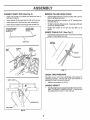
CONNECT SHIFT ROD (See Fig. 6)
o Insert end of shift rod farthest from bend into hole of
shift lever indicator.
• Insert hairpin clip through hole of shift rod to securer
° Insert other end of shift rod into hole in shift lever.
° Insert second hairpin clip through hole of shift rod°
ATTACHTHISEND ATTACHTHIS
TOSHIFTLEVER ENDTOSHIFT
INDICATOR LEVER _
SHIFT ROD
SHIFT
...................... i,i i,,
HAIRPIN SHIFT
CLIP LEVER
INDICATOR
SHIFT
i ii i
HAIRPIN CLIP
SHIFT ROD
FIG. 6
REMOVE TILLER FROM CRATE
, Adjust handte assembyto lowest position, Be sure lock
lever is tightened securely°
o Make sure shift lever indicator is in "N" (neutral) posi-
tion (See Fig. 6)
° Tilt tiller forward by lifting handle° Separate cardboard
cover from leveling shield.
o Rotate tiller handle to the right and pull tiller out of
carton.
INSERT CABLE CLIP (See Fig. 7)
° Insert plastic cable clip into hole on the back of handle
column_ Push cables into clip.
HANDLE
COLUMN
-\
CABLES
FIG. 7
CHECK TIRE PRESSURE
The tires on your unit were overinflated at the factory for
shipping purposes, Correct and equal tire pressure is
important for best tilling performance°
o Reduce tire pressure to 20 PSI°
HANDLE HEIGHT
• Handle height may be adjusted to better suit operator.
(See 'TO ADJUST HANDLE HEIGHT" in the Service
and Adjustments section of this manual)_
8

L_ ,.i ..... I ' ,.... I" "'111"'11'11'""='"1'""11'1"1 ........ I1'1 I1'11"11"1'1111 , , ,I,,,,,,,I,, "1"'11'1' '
OPEF ATmON
.,, .............. ,,.. i ,,,i i, i ii iii,,i, ,i,,i,,,i,M'IIII "11'"'1''11I
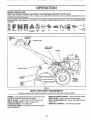
KNOW YOUR TILLER
READ THIS OWNER'S MANUAL AND SAFETY RULES BEFORE OPERATING YOUR TILLER,
Compare the illustrations with your tiller to familiarize yourself with the location of various controls and adjustments, Save
this manual for future reference°
These symbols may appear on your Tiller or in literature supplied with the product. Learn and understand their
meaning.
T{LL|NG FORWARD NEUTRAL REVERSE
CAUTION ENG1NE ENGINE
OR WARNING ON OFF
FAST SLOW
STOP O
CHOKE FUEL OtL
DRIVE _ THROTTLE
CONTROL _ CONTROL
BAR
SHIFT LEVER
INDICATOR
PRIMER
DEPTH STAKE _
LEVELING _ _ _ _ _\_
SHIELD
OUTER
SIDE
SHIELD
RECOIL
STARTER
HANDLE
FIG. 8
MEETS ANSI SAFETY REQUIREMENTS
Our tillers conform to the safety standards of the American National Standards Institute,
PRIMER - pumps additional fuel from the carburetor to the
cylinder for use when starting a cold engine,
DEPTH STAKE - Controls depth at which tiller will dig
DRIVE CONTROL BAR _ Used to engage tines,
LEVELING SHIELD * Levels tilled soil.
OUTER SIDE SHIELD - Adjustable to protect small plants
from being buried.
RECOIL STARTER HANDLE - Used to start the engine,
SHIFT LEVER - Used to shift transmission gears,
SHIFT LEVER INDICATOR - Shows which gear the trans-
mission is in_
THROTTLE CONTROL - Controls engine speed..

The operation of any tiller can result in foreign objects thrown into the eyes, which can
result in severe eye damage. Always wear safety glasses or eye shields before starting
your tiller and while tilling. We recommend a wide vision safety mask over the spectacles
or standard safety glasses.
i i, i,ili,i, i i ...................................... ill ,_l,r
HOW TO USE YOUR TILLER
Know how to operate all controls before adding fuel and
oil or attempting to start engine_
STOPPING (See Fig. 9)
TINES AND DRIVE
- Release drive control bar to stop movement.
o Move shift lever to "N" (neutral) position.
ENGINE
o Move throttle control to "STOP" position.
o Never use choke to stop engine_
DRIVE CONTROL BAR
"ENGAGED" POSITION
.THROTTLE
SHIFT
LEVER
DRIVE CONTROL BAR
"DISENGAGED" POSITION
FIG. 9
TINE OPERATION - WITH WHEEL DRIVE
• Always release drive control bar before moving shift
lever into another position.
• ..... r "T"
Tine movement ts achieved by mowng shift leve to
(till) position and engaging drive control bar.
FORWARD- WHEELS ON LY/TINES STOPPED
• Release drive control bar and move shift lever indicator
to "F" (forward)position Engage drive control bar and
tiller will move forward.,
REVERSE - WHEELS ONLY/TINES STOPPED
= DO NOT STAND DIRECTLY BEHIND TILLER.,
° Release the drive control bar.
° Move throttle control to "SLOW" position.
• Move shift lever indicator to "R" (reverse) position.
= Hold drive control bar against the handle to start tifier
movement.
10
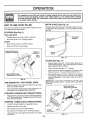
DEPTH STAKE (See Fig. 10)
The depth stake can be raised or lowered to allow you more
versatile tilling and cultivating, or to more easily transport
'our tiller°
SHALLOWES=I
TILLING
TILLING
POSITION
TILLING (See Fig, 11)
o Release depth stake pin. Pull the depth stake up for
increased tilling depth. Place depth stake pin inhole of
depth stake to lock in position
. Place shift lever indicator in 'q" position,
o Hold the drive control bar against the handle to start
tilling movemenL Tines and wheels will both turn,
- Move throttle control to "FAST" position for deep tilling.
To cultivate, throttle control can be set at any desired
speed, depending on how fast or slow you wish to
cultivate.
IMPORTANT: ALWAYS RELEASE DRIVE CONTROL BAR
BEFORE MOVING SHIFT LEVER INTO ANOTHER
POSITION
DEPTH STAKE PIN
"RELEASED" POSITION
\
NUT "A"
"LOCKED"
POSITION
OUTER NUT "B"
SIDE SHIELD
FIG. 11

...... =,, = =,,H, ,=.... =,,,,,=,,,,,H,
OPERAT!ON
, = , =,m
i u u, 1, , lu,,,H....
TURNING • To read proper'level, tighten engine oil cap each time.
ii
°
o
Release the drive control bar,
Move throttle control to "SLOW" position.
Place shift lever indicator in "F" (forward) position.
Tines will net turn
Lift handle to raise tines out of ground.
Swing the handle in the opposite direction you wish to
turn, being careful to keep feet and legs away from
tines.
When you have completed your turn-around, release
the drive control barand lower handle. Place shift lever
in "T" (till) position and move throttle control to desired
speed, To begin tilling, hold drive control bar against
the handle,
• Reinstall engine oil cap and tighten.
• For approximate capacity see "PRODUCT SPECIFI-
CATIONS" on page 3 of this manual. All oil must meet
A.PJ. Service Classification SF or SG.
= For cold weather operation you should change oil for
easier starting (See oil viscosity chart in the Customer
Responsibilities section of this manual),,
° To change engine oil, see the Customer Responsibili-
ties section in this manual,,
OUTER SIDE SHIELDS (See Fig. 11)
The front edges of the outer side shields are slotted so that
the shields can be raised for deep tilling and lowered for
shallow tilling to protect small plants from being buried.
Loosen nut "A" in slot and nut "B"_ Move shield to desired
position (both sides)° Retighten nuts.
OIL FILL
CAP/DIPSTICK
TO TRANSPORT
,,, =,,=,=,,=,,=1=....
CAUTION: Before lifting or transport-
ing, allow tiller engine and muffler to
cool. Disconnectsparkplugwire. Drain
gasoline from fuel tank.
.......... i , ,, i ,i iiil,,,,,,i,,llqi,
AROUND THE YARD
• Release the depth stake pin,. Move the depth stake
down to the top hole for transporting the tiller, Place
depth stake pin in hole of depth stake to lock inposition,
This prevents tines from scuffing the ground.
o Place shift lever indicator in "F" (forward) position for
transporting°
• Hold the drive cont{ol bar against the handle to start
tiller movement, Tines will net turn.
• Move throttle control to desired speed,
AROUND'TOWN
° Disconnect spark plug wire,
° Drain fuel tank.
- Transport in upright position to prevent oil leakage.
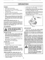
BEFORE STARTING ENGINE
IMPORTANT: BE VERY CAREFUL NOT TO ALLOW DIRT
TO ENTER THE ENGINE WHEN CHECKING OR ADDING
OIL OR FUEL. USE CLEAN OtL AND FUEL AND STORE
IN APPROVED, CLEAN, COVERED CONTAINERS. USE
CLEAN FILL FUNNELS.
CHECK ENGINE OIL LEVEL (See Fig. 12)
• The engine in your unit has been shipped, from the
factory, already titled with SAE 30 summer weight oil,
= Be sure tiller istevel and the area around oil fill isclean_
= Check oil level before each use,, Add oil if needed° Fill
to full line on dipstick.
11
FIG. 12
ADD GASOLINE
= Fill fuel tank Use fresh, clean, regular unleaded
gasoline. (Use of leaded gasoline wilt increase carbon
and lead oxide deposits and reduce valve life.)
IMPORTANT: WHEN OPERATING IN TEMPERATURES
BELOW 32°F (0°C), USE FRESH, CLEAN, WINTER GRADE
GASOLINE TO HELP INSURE GOOD COLD WEATHER
STARTING.
WARNING: Experience indicates that alcohol blended
fuels (called gasohot or using ethanol or methanol) can
attract moisture which leads to separation and formation of
acids during storage° Acidic gas can damage the fue!
system of an engine while in storage. To avoid engine
problems, the fuel system should be emptied before
storage of 30 days or longer, Drain the gas tan k,start the
engine and let it run untit the fuel lines and carburetor are
empty_ Use fresh fuel next season. See Storage section
of this manual for additional information, Never use engine
or carburetor cleaner products inthe fuel tank or permanent
damage may occur_
&
CAUTION: Fill to within 1/2 inch of top
of fuel tank to prevent spills and to
allow for fuel expansion, if gasoline is
accidentally spilled, move machine
away from area of spill. Avoid creating
any source of ignition until gasoline
vapors have disappeared.
Do not overfill. Wipe off any spilled oil
or fuel, Do not store, spill or use gaso-
line near an open flame.

OPERATUON
i i, ,,,11
TO START ENGINE (See Fig. 7)
When starting engine for the first time or if engine has run
out of fuel, itwill take extra pulls ofthe recoil starter to move
fuel from the tank to the engine.
= Make sure spark plug wire is properly connected.
• Move shift lever indicator to "N" (neutral) position..
• Place throttle controlin "FAST" po_ition.
= To start acold engine, push primer five (5) times before
trying to start. Use a firm push. This step is not usually
necessary when starting an engine which has already
run for a few minutes,
o Grasp recoil starter handle with one hand and grasp
tiller handle with other hand. Pull rope out slowly until
engine reaches start of compression cycle (rope will
pull slightly harder at this point)°
° Pull recoil starter handle quickly. Do not let starter
handle snap back against starter.
= Allow engine to warm up for a few minutes before
engaging tines.
NOTE: In cooler weather it may be necessary to repeat
priming steps., in warmerweather over priming maycause
flooding and engine will not start° If you do flood engine,
wait a few minutes before attempting to start and do not
repeat priming steps.
PRIMER
RECOIl. STARTER
HANDLE
FIG. 13
TILLING HINTS
................. ,,=,,11.........
CAUTION: Until you are accustomed to
handling your tiller, start actual field
use with throttle in slow position (m!d-
way between "FAST" and "IDLE").
, , ,i, i,,11.... i i,=
° Tilling is digging into turning over, and breaking up
packed soil before" planting° Loose, unpacked soi!
helps root growth° Best tilling depth is 4 to 6'. A tiller
will also clear the soil of unwanted vegetation, The
decomposition of this vegetable matter enriches the
soil. Depending on the climate (rainfall and wind), it
may be advisable to till the soil atthe end ofthe growing
season to further condition the soil.
o For easier handling of your tiller, leave about 8 inches
of untilled soil between the first and second tilling
passes. The third pass will be between the first and
second (See Fig. 14).
12
o Soil conditions are importantfor proper tilling° Tines will
not readily penetrate dry, hard soil which may contrib-
ute to excessive bounce and difficult handling of your
tiller° Hard soi! should be moistened before tilling;
however, extremely wet soil will "ball-up" or clump
dudng tilling° Wait until the soil is less wet in order to
achieve the best results. When tilling in the fall, remove
vines and long grass to prevent them from wrapping
around the tine shaft and slowing your tilling operation.
° Do not lean on handle° This takes weight off the wheels
and reduces traction. To get through a reaIly tough
section of sod or hard ground, apply upward pressure
on handle or lower the depth stake.
77 _1f
i/
/J
//
//
/i'
FIG. 14
CULTIVATING
Cultivating is destroying the weeds between rows to pre-
vent them from robbing nourishment and moisture from the
ptants. At the same time, breaking up the upper layer of soil
crust will he}p retain moisture in the soil. Best digging depth
is 1" to 3". Lower the outer side shields to protect small
plants from being buried.
= Cultivate up and down the rows at a speed which wi!)
allow tines to uproot weeds and leave the ground in
rough condition, promoting no further growth of weeds
and grass (See Fig. 15).
© O
\_1
FIG. 15
TINE SHEAR PINS
The tine assemblies on your tiller are secured to the tine
shaft with shear pins (See 'q-INE REPLACEMENT" in the
Service and Adjustments section of this manual)°
If the tiller is unusually overloaded or jammed, the shear
pins are designed to break before internal damage occurs
to the transmission°
, If shear pin(s) break, replace only with those shown in
the Repair Parts section of this manual

................ i, , .... , ........ ii,, ,,,=....
CUSTOMER RESIPON BILUTIES
, , =,,H=................................................ ,= ' ,
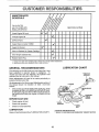
SCHEDULE
REGULAR SERVICE
= , , ,= ,,= H,= ........ H,u H= HH '' = I
Check Engine 0it Level _#' _#'
=lull Ill, =!,
Change Engine Oil 1_1,2
= ,H , 111 ..................
Oil Pivot Points
Inspect Spark Attester / Muffler
= i
Inspect AIr Screen _'
=ui!==,=
Clean or Replace Air Cfeaner Cartridge _2
1,,,,1, ,111 ==u
Clean Engine Cylinder Fins
Replace Spark Plug _#_
1 - Chango mote often when operating under a heavy load or in high ambient temperatures,
2 - Service more often when operating in ditty or dusty conditions
GENERAL RECOMMENDATIONS
The warranty on this tiiler does not cover items that have
been subjected to operator' abuse or' negligence° To
receive fufl value from the warranty, the operator must
maintain tiller as instructed in this manual,
Some adjustments wilt need to be made periodically to
properly maintain your tiller°
All adjustments in the Service and Adjustments section of
this manual should be checked at least once each
seasom
o Once a year you should replace the spark pfug, clean
or replace air filter, and check tines and belts for'wear.
A new' spark plug and clean air filter assure proper air-
fuel mixture and help your engine run better and last
longer,
BEFORE EACH USE
= Check engine oil level°
• Check tine operation°
, Check for' loose fasteners.
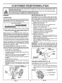
LUBRICATION
Keep unit well lubricated (See "LUBRICATION CHART").
LUBRiCATiON CHART
* THROTTLE
CONTROL
** ENGINE
PIN
* LEVELING
HINGES
* IDLER
BRACKET
WHEEL
HUB
* SAE 30 OR 10W-30 MOTOR OIL
** REFER TO CUSTOMER RESPONSIBILITIES "ENGINE" SECTION
13

m ,_..................... n,,,,, i,, ,,i
CUSTOMER RESPONSBB L TmES
,, ii,lll,r,t
Disconnect spark plug wire before performing any maintenance (except carburetor adjustment) to prevent
accidental starting of engine.
Preventfires{ Keepthe engine free of grass, leaves, spiliedoil, orfuel. Removefuel from tank before tipping
unitfor maintenance. Cleanmuffler area of all grass, dirt, and debris°
Do not touch hot muffler or cylinder fins as contact may cause burns.
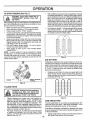
ENGINE
LUBRICATION
Use only high quality detergent oil rated with API service
classification SF, SG or SH Select the oil's SAE viscosity
grade according to your expected temperature,
SAE VISCOSITY GRACES
_F "20_ 0_ 30° 32_ 40° 60 _ B0_ 100_
°c ._oo .{oo ._oo oo ,'o, _oo 30° 40°
TEMPERATURE RANGE ANTICIPATED BEFORE NEXT OIL CHANGE
FIG. 16
NOTE: Although multi-viscosity oils(5W-30, 10W*30, etco)
improve starting in cold weather, these multi-viscosity oils
will result in increased oil consumption when used above
32°F (0°C). Check your engine oil level more frequently to
avoid possible engine damage from running low on oil
Change the oil after every 25 hours of operation or at least
once a year ifthe tractor is not used for25 hours inone year,
Check the crankcase oil level before starting the engine
and after each five (5) hours of continuous use. Add SAE
30 motor oil or equivalent. Tighten oil filler plug securely
each time you check the oil level.
TO CHANGE ENGINE OIL (See Figs. 16 and 17)
Determine temperature range expected before oil change,
All oil must meet API service classification SF, SG or SHo
• Be sure tiller is on level surface.
- Oi! will drain more freely when warm°
. Use a funnel to prevent oil spill on tiller, and catch oil in
a suitable container_
. Remove oil drain plug and oil fill cap/dipstick, Be
careful not to allow dirt to enter the engine,
For easier removal of plug use 7/16 12 Pt. socket with
extension.
. Tip tiller forward to drain oil,
• After oil has drained completely, replace oil drain plug
and tighten securely°
• Refill engine with oil through oil fill tube. See "CHECK
ENGINE OIL LEVEL" in the Operation section of this
manual.
o,,.i
PLUG_
FIG, 17
14
AIR FILTER (See Fig. 18)
Your engine will not run properly using a dirty air filter,,
Clean the foam pre-cleaner after every 25 hours of opera*
tion or every season° Service paper cartridge every 100
hours of operation or every season, whichever occurs firsL
Service air cleaner more often under dusty conditions,,
° Remove cover screw and cover,
TO SERVICE PRE-CLEANER
• Remove foam pre-cleaner from air cleaner cover.,
° Wash it in liquid detergent and water.
o Squeeze it dry in a clean cloth,
• Saturate it in engine oil Wrap it in clean, absorbent
cloth and squeeze to remove excess oil
o If very dirty or damaged, rep{ace pre-cieaner.
• Reinstall pre-cleaner into air cleaner cover.
. ReinstalI cover and secure screw.
TO SERVICE CARTRIDGE
= Carefully remove cartridge to prevent debris from en-
tering carburetor. Clean base carefully to prevent
debris from entering carburetor._
° Clean cartridge by tapping gently on flat surface° Ifvery
dirty or damaged, replace cartridge.
. Reinstall cartridge, cover with pre-cleaner and secure
with screw,
IMPORTANT: PETROLEUM SOLVENTS, SUCH AS
KEROSENE, ARE NOT TO BE USED TO CLEAN THE
CARTRIDGE, THEY MAY CAUSE DETERIORATION OF
THE CARTRIDGE. DO NOT OIL CARTRIDGE DO NOT
USE PRESSURIZED AIR TO CLEAN OR DRYCARTRIDGE°
FOAM
PRECLEANER
COVER
AIRCLEANER
CARTRIDGE
COVER
SCREW
FIG. 18
COOLING SYSTEM (See Fig. 19)
Your engine isair cooled° For proper engine performance
and long life keep your engine clean°
• Clean air screen frequently using a stiff-bristled brush°
° Keep cylinder fins, levers, and linkage free of dirt and
chaff..
MUFFLER .<j---_, _ CYLINDER FINS
AIR SCREEN
FIG. 19

, IH ,I,H,I,
CUSTO ESPONSBBmLmTIES
, ,,,, ,ii,i i ,i ,ml,m i1,1 ,,, m,ii
MUFFLER TRANSMISSION
Do not operate tiller without muffler.. Do not tamper with
exhaust system. Damaged mufflers or' spark arresters
could create a fire hazard° Inspect periodically and replace
if necessary, if your engine is equipped with a spark
arrester screen assembly, remove every 50 hours for
cleaning and inspection Replace if damaged
SPARK PLUG
Replace spark plugs at the beginning of each tilling season
or after every 50 hours of use, whichever comes first. Spark
plug type and gap setting is shown in "PRODUCT SPECI-
FICATIONS" on page 3 of this manual.
Your transmission is sealed and will only require lubrication
if serviced,
CLEANING
° Clean engine, wheels, finish, etc. of alt foreign matter.
o Keep finished sudaces and wheels free of all gasoline,
oil, etc..
o Protect painted surfaces with automotive type wax..
We do not recommend using a garden hose to clean your
unit unless the muffler, air filter and carburetor are covered
to keep waterouL Water in engine can result in a shortened
engine life
$E
ADJUSTMENTS
CAUTION: Disconnect spark plug wire from spark plug and place wire where it cannot come into
contact with plug,
, ,r_r ,,r, i
TILLER
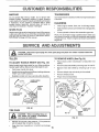
TO ADJUST HANDLE HEIGHT (See Fig. 20)
Select handle height best suited for your tilling conditions,
Handle height will be different when tiller digs into soil,
= First loosen handle lock lever,
= Handle can be positioned at different settings between
"HIGH" and "LOW" positions,
. Retighten handle lock lever securely after adjusting,
HANDLE (HIGH
)
HANDLE
LOCK
LEVER
HANDLE (LOW
POSITION)
I
FIG. 20
TIRE CARE
_ CAUTION: When mounting tires, un-
less beads are seated, overinflation
can cause an explosion,
,, , i, , ii , ,
• Maintain 20 pounds of tire pressure. If tire pressures
are not equal, tiller will pull to one side,
• Keep tires free of gasoline or oil which can damage
rubber°
15
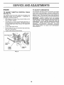
l'O REMOVE WHEEL (See Fig. 21)
o Place blocks under transmission to keep tiller from
tipping.
o Remove outer side shield by _emoving nuts"A" and"B"
- Remove inner side shield by removing nuts "C" and
"D"_
- Remove hairpin clip and clevis pin from wheel
o Remove wheel and tire_
- Repair tire and reassemble°
HAIRPIN
CLIP
INNER SIDE
i
SHIELD
OUTER
NUT "B" SIDE
SHIELD
FIG. 21

, iiiiil,,,u,,ul , ,,11,,i
SERVmCE AN ADJUSTMENTS
i1,,
TO REMOVE BELT GUARD (See Fig. 22)
• Remove L.H, inner and outer side shields (See "TO
REMOVE WHEEL" in this section of this manual),
o Remeve hairpin clip andclevis pinfromleffwheeL Pull
wheef out from tiller about t inch
o Remove two (2) cap nuts and washers from side of belt
guard,
o Remove hex nut and washer from bottom of belt guard
(located behind wheel)
• Pull belt guard cut and away from unit
. Replace belt guard by reversing above procedure
BELT GUARD
/ _z__\
CAP NUT _l_ _
AND WASHER
CAP NUT
AND WASHER
=o, x.o,
WASHER
"" BEHIND
TIRE)
\ HAIRPIN CLIP AND
CLEVIS PiN
FIGo 22
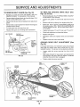
TO REPLACE GROUND DRIVE BELT (See
Figs. 22 and 23)
o Remove belt guard (See''TO REMOVE BELT GUARD"
in this section of this manual)
• Loosen belt guides "A" and "B" and atso nuts "C" and
° Remove old belt by slipping from engine pulfey first,
= Place new belt in groove of transmission pulley and
into engine pulley BELT MUST BE IN GROOVE ON
TOP OF IDLER PULLEY NOTE POSITION OF BELT
TO GUIDES,
o Tighten belt guides "A" and "B" and nuts "C" and "D",
= Check belt adjustment as described below
, Replace belt guard.
, Reposition wheel and replace clevis pin and hairpin
ciip_
- Replace inner and cuter side shields.
GROUND DRIVE BELT ADJUSTMENT (See
Fig. 23)
For proper belt tension, the extension spring should have
about 5/8 inch stretch when drive control bar is in "EN-
GAGED" position This tension can be attained as follows:
• Loosen cable clip screw securing the drive control
cable.
, Slide cable forward for less tension and rearward for
more tension until about 5/8 inch stretch is obtained
while the drive control bar is engaged..
Tighten cable clip screw securely..
ENGINE
PULLEY
BELT CABLE CLiP
GUIDE "A' SCREW
BELT
CONTROL
CABLE
IDLER
PULLEY TRANSMISSION
PU LLEY
FIG. 23_
EXTENSION
SPRING
16

=,n, = , ,=,,,,,,===,_
SERVICE
AND ADJUSTMENTS
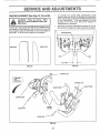
TINE REPLACEMENT (See Figs. 24, 25 and 26)
,,i ,11 ii i1,1.i,. ,,
gloves or other protection when han-
dling tines.
A badly worn tine causes'your ii'i'lerto work harder and dig
mote shallow., Most important, worn tines cannot chop and
shred organic matter as effectively nor bury it as deeply as
good tines A tine this worn needs to be replaced.
NEW TINE
WORN TINE
FIG. 24
- To maintain the superb tilling performance of this
machine the tines should be checked for' sharpness,
wear, and bending, particularly the tines which are next
to the transmission. If the gap between the tines
exceeds 3-I/2 inches they should be replaced or
straightened as necessary
o New tines should be assembled as shown in Fig. 26.
Sharpened tine edges will rotate rearward from above..
TINE 1
I
1
[
3-1t2" MAX--4
_TINE
FIG. 25
HAIRPIN CLIP
COUNTER
TINE
ROTATION
HAIRPIN CLIP
SHARP EDGE
SHARP EDGE
SHEAR PiN
SHEAR PIN
EDGES
FIG. 26
17

ENGINE
TO ADJUST THROTTLE CONTROL CABLE
(See Fig. 27)
The throttle control has been preset at the factory and
adjustment should not be necessary° If adjustment is
necessary, proceed as follows:
o With engine not running, move remote throttle control
[ever to "FAST" position.
° If throttle lever on engine touches high speed stop, no
further adjustment is necessary, tf throttle lever does
not touch high speed stop, continue with adjustment
procedure_
• Loosen cable clamp screw°
o Move throttle lever up until ittouches high speed stop,
and hold in this position_
o Tighten cable clamp screw securely..
TO ADJUST CARBURETOR
The carburetor has been preset at the factory and adjust-
ment should not be necessary, However, engine perfor-
mance can be affected by differences in fuel, temperature,
altitude or load, If the carburetor does need adjustment,
contact your nearest authorized service cente r/department
IMPORTANT: NEVER TAMPER WITH THE ENGINE
GOVERNOR, WHICH IS FACTORY SET FOR PROPER
ENGINE SPEED, OVERSPEEDING THE ENGINE ABOVE
THE FACTORY HIGH SPEED SETTING CAN BE
DANGEROUS_ IF YOU THINK THE ENGINE-GOVERNED
HIGH SPEED NEEDS ADJUSTING, CONTACT YOUR
NEAREST AUTHORIZED SERVICE CENTER/
DEPARTMENT, WHICH HAS THE PROPER EQUIPMENT
AND EXPERIENCE TO MAKE ANY NECESSARY
ADJUSTMENTS
HIGH SPEED STOP \
%
THROTTLE /
CABLE
CABLE
CLAMP
SCREW
THROTTLE
LEVER
FIG. 27
18

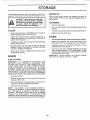
Immediately prepare your tiller' for storage at the end of the
season or if the unit will not be used for 30 days or more.
= ,,,,i .... i,
CAUTION: Never store the tiller with
gasoline in the tank inside a building
where fumes may reach an open flame
or spark. Allow the engine to cool
before storing in any enclosure,
..... i,,,,,i ........................
TILLER
o Clean entire tiller'(See "CLEANING" in the Customer
Responsibilities section of this manual).
- Inspect and replace belts, if necessary (See belt re-
placement instructions in the Service and Adjustments
section of this manual),
o Lubricate as shown in the Customer Responsibilities
section of this manual,,
• Be sure that all nuts, bolts and screws are securely
fastened° Inspect moving parts fordamage, breakage
and wear'. Replace if necessary.
• Touch up al] rusted or chipped paint surfaces; sand
lightly before painting,.
ENGmNE
FUEL SYSTEM
IMPORTANT: IT IS IMPORTANT TO PREVENT GUM
DEPOSITS FROM FORMING IN ESSENTIAL FUEL
SYSTEM PARTS SUCH AS THE CARBURETOR, FUEL
FILTER, FUEL HOSE, OR TANK DURING STORAGE_
ALSO, EXPERIENCE INDICATES THAT ALCOHOL
BLENDED FUELS (CALLED GASOHOL OR USING
ETHANOL OR METHANOL) CAN ATTRACT MOISTURE
WHICH LEADS TO SEPARATION AND FORMATION OF
ACIDS DURING STORAGEI ACIDIC GAS CAN DAMAGE
THE FUEL SYSTEM OF AN ENGINE WHILE IN STORAGE.
= Drain the fuel tank.
o Start the engine and let it run until the fuel lines and
carburetor are empty.,
. Never use engine or carburetor cleaner products in the
fuel tahk or permanent damage may occur.
= Use fresh fuel next season.
NOTE: Fuel stabilizer is an acceptable alternative in
minimizing the formation of fuel gum deposits during stor-
age_ Add stabilizer to gasoline in fuel tank or storage
container. Always follow the mix ratio found on stabilizer
container. Run engine at least 10 minutes after adding
stabilizer to allowthestabilizerto reach the carburetor. Do
not drain the gas tank and carburetor' ifusing fuel stabilizer.
ENGINE OIL
Drain eli (with engine warm) and replace with clean oil.
(See "ENGINE" in the Customer Responsibilities section of
this manual)_
CYLINDERS
o Remove spark plug
o Pour1 ounce (29 ml) of oilthrough spark plug hole into
cylinder°
o Pull starter' handie slowly several times to distribute oil
o Replace with new spark plug.
OTHER
• Do not store gasoline from one season to another.
. Replace your' gasoline can if your can starts to rust_
Rust and/or dirt in your' gasoline will cause problems.
- If possible, store your unit indoors and cover it to give
protection from dust and dirt.
,, Cover your unit with a suitable protective cover' that
does not retain moisture. Do not use plastic. Plastic
cannot breathe which allows condensation to form and
will cause your unit to rust.
IMPORTANT: NEVER COVER TILLER WHILE ENGINE
AND EXHAUST AREAS ARE STILL WARM,
19

I'H'""H" I" I" I
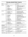
TROUBLESHOOTING POINTS
,, iii i, i,i P,,,ll , , ,, , LILI,]I','U"I'Nr,L',1,', ....................
PROBLEM CAUSE CORRECTION
Wli! not start
i,i ii i , ,,===,1
Hard to start
i, H,,
Loss of power
Engine overheats
Excessive bounce/
difficult handling
Soil balls up or clumps
Engine rune but tiller
won't move
Engine runs but labors
whentilling
Tines will not rotate
1 Out of fuel
2 Engine not "CHOKED" propedy
3 Engine flooded
4 Dirty air cleaner
5 Water in fuel
6 Clogged fuel tank
7 Loose spark plug wire
8 Bad spark plug ar improper gap
9 Carburetor out of adjustment,
10 Oil soaked air filter
t Throttle contro} not sat properly
2 Dirty air cleaner
3 Bad spark plug or improper gap
4 State or dirty fuel
5 Loose spark plug wire
6 Carburetor out of adjustment
ii H,"H',N
1 Engine is overloaded
2 Dirty air cleaner
3 Low oil tevelfdtrty oil
4 Faulty spark plug
5 Oil in fuel
6 Stale or dirty fue}
7 Water in fuel
8 Clogged fuel tank
9 Spark plug wire loose
10 Dirty engine air screen
11 Dirty/clogged muffler,
t2 Carburetor out of adiustment,
13 Poor compression
, 'H,H"" I","
1 Low oil level/dirty oil
2 Dirty engine air screen
3 Dirty engine
4 Partially plugged muffler
5 Improper carburetor adjustment
i, i , i ll,l,,i,,
1 Ground too dry and hard
i i i, :::::::::::::::::::::::::::::::::::
1 Ground too wet.
1 Drive control bar is not engaged
2 V-bait not correctly adjusted
3 V-belt Isoff pulley(s)
• 1 Tilling too deep
2 Throttle control not properly adjusted
3 Carburetor out of adjustment
i ,, ,,IHI '"HI'H ........ I ' I .................
1 Shear pin(s) broken
I, Fill fueftank
2 See '3"0 START ENGINE" in Operation section
3 Wait several minutes before attempting to start
4 Clean or replace air cleaner cartridge
5 Drain fuel tank and carburetor, and refitl tank with fresl_
gasoline
6 Remove fuel tank and clean
7 Make sure spark plug wire is seated properly on plug
8 Replace spark plug or adjust gap
9 Make necessary adjustments
10 Replace air filter
t Place throttle control in 'FAST" position
2 Ciean or replace air cleaner cartridge
3 Repiace spark plug or adjust gap
4 Drain fuel tank and refill with fresh gasoline,
5 Make sure spark plug wire is seated properly on plug
6 Make necessary adjustments
1 Set depth stake for shallower tilling
2 Clean or replace air cleaner cartridge
3 Check oil level/change oil
4 Clean and regap or change spark pSug
5 Drain and clean fuel tank and refill, and clean carburetor
6 Drain fuel tank and refill with fresh gasoline,
7 Drain fuel tank and carburetor, and refill tank with fresh
gasoline
8 Remove rue{ tank and clean
9 Connect and tighten spark plug wire
10 Clean engine air screen
1! Clean/replace muIfler
12 Make necessary adjustments
!3 Contact an authorized service center/department
i i i ii i
1 Check oil level/change oil
2, Clean engine air screen,
3, Ctean cylinder fins, air screen, and muffter area
4 Remove and clean muffler
5 Adjust carburetor to richer position
Moisten ground or wait for more favorable soil
conditions,
Wait for more favorable soil conditions,
t Engage drive control
2 Inspect/adjust V-belt
3 inspect Vobelt
1 Set depth stake for shallower tilling,
2 Check throttle control setting
3 Make necessary adjustments
1 Repiace shear pin(s)
2O
Page is loading ...
Page is loading ...
Page is loading ...
Page is loading ...
Page is loading ...
Page is loading ...
Page is loading ...
Page is loading ...
Page is loading ...
Page is loading ...
Page is loading ...
Page is loading ...
-
 1
1
-
 2
2
-
 3
3
-
 4
4
-
 5
5
-
 6
6
-
 7
7
-
 8
8
-
 9
9
-
 10
10
-
 11
11
-
 12
12
-
 13
13
-
 14
14
-
 15
15
-
 16
16
-
 17
17
-
 18
18
-
 19
19
-
 20
20
-
 21
21
-
 22
22
-
 23
23
-
 24
24
-
 25
25
-
 26
26
-
 27
27
-
 28
28
-
 29
29
-
 30
30
-
 31
31
-
 32
32


Craftsman 917.293650 Owner's manual
- Category
- Mini tillers
- Type
- Owner's manual
- This manual is also suitable for
Ask a question and I''ll find the answer in the document
Finding information in a document is now easier with AI
Related papers
-
Craftsman 917299881 Owner's manual
-
-
-
-
-
-
-
-
-