Page is loading ...

KitchenAid _
FOR THE WAY IT'S MADE. _
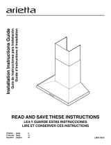
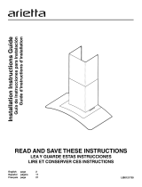
30" (76.2CM)AND 36" (91.4CM)
WALL-MOUNT CANOPY RANGE HOOD
'// ° ".... 1
' ........ ..4.................. _"_'' S_]/?° .......... "_ ¢"_¢::_
For questions about features, operation/performance, parts, accessories or service, call: 1-800-422-1230
or visit our website at www, kitchenaid,com
In Canada, for assistance, installation and service, call: 1-800-807-6777
or visit our website at www, kitchenaid,ca
HO-I-I-EDE CUISINIERE POUR MONTAGE MURAL
30" ET36" (76,2CM ET91,4CM)
?J <',,:_'I'h;'_""'_"CYI(.;_JLJ<:D_!? ...........':""" '
....... :.<:;_I;_.3 CYI'
Au Canada, pour assistance, installation ou service composez le 1-800-807-6777
ou visitez notre site web &www.kitchenaid.ca
Table of Contents/Table des matieres ............................................................................. 2
IMPORTANT: READ AND SAVE THESE INSTRUCTIONS.
FOR RESIDENTIAL USE ONLY.
IMPORTANT : LIRE ET CONSERVER CES INSTRUCTIONS.
POUR UTILISATION RI_SIDENTIELLE UNIQUEMENT.
LI3ZCB/W10322990G

TABLE OF
RANGE HOOD SAFETY ................................................................. 2
INSTALLATION REQUIREMENTS ................................................ 4
Tools and Parts ............................................................................ 4
Location Requirements ................................................................ 4
Venting Requirements .................................................................. 5
Electrical Requirements ............................................................... 6
INSTALLATION INSTRUCTIONS .................................................. 7
Prepare Location .......................................................................... 7
Install Range Hood ....................................................................... 8
Connect Vent System .................................................................. 8
Make Electrical Connection ......................................................... 9
Install Vent Covers ..................................................................... 10
Complete Installation ................................................................. 10
CONTENTS
RANGE HOOD USE ...................................................................... 11
Display ........................................................................................ 11
Bottom Lights............................................................................. 11
Timer........................................................................................... 12
Fan Speed .................................................................................. 12
Top (Ambient) Lights .................................................................. 12
RANGE HOOD CARE ................................................................... 13
Cleaning ...................................................................................... 13
WIRING DIAGRAM ...................................................................... 14
ASSISTANCE OR SERVICE ......................................................... 15
In the U.S.A ................................................................................ 15
Accessories ................................................................................ 15
In Canada ................................................................................... 15
WARRANTY .................................................................................. 16
TABLE DES
SI_CURITI_ DE LA Ho'n'E DE CUISINII_RE ............................... 17
EXIGENCES D'INSTALLATION ................................................... 19
Outils et pieces ........................................................................... 19
Exigences d'emplacement ......................................................... 19
Exigences concernant I'evacuation ........................................... 20
Specifications electriques .......................................................... 21
INSTRUCTIONS D'INSTALLATION ............................................ 22
Preparation de I'emplacement ................................................... 22
Installation de la hotte ................................................................ 23
Raccordement du circuit d'evacuation ...................................... 23
Raccordement electrique ........................................................... 24
Installation des cache-conduits ................................................. 25
Achever I'installation .................................................................. 25
MATII RES
UTILISATION DE LA HOTTE ....................................................... 25
Affichage ..................................................................................... 25
Lampes inferieures..................................................................... 26
Minuterie ..................................................................................... 26
Vitesse du ventilateur ................................................................. 26
Lampes (d'ambiance) superieures ............................................. 26
ENTRETIEN DE LA Ho'n'E .......................................................... 27
Nettoyage ................................................................................... 27
SCHI_MA DE C,&,BLAGE............................................................... 29
ASSISTANCE OU SERVICE ......................................................... 30
Au Canada .................................................................................. 30
Accessoires ................................................................................ 30
GARANTIE ..................................................................................... 31
RANGE HOOD SAFETY
Your safety and the safety of others are very important.
We have provided many important safety messages in this manual and on your appliance. Always read and obey all safety
messages.
This is the safety alert symbol.
This symbol alerts you to potential hazards that can kill or hurt you and others.
All safety messages will follow the safety alert symbol and either the word "DANGER" or "WARNING."
These words mean:
You can be killed or seriously injured if you don't immediately
follow instructions.
You can be killed or seriously injured if you don't follow
instructions.
All safety messages will tell you what the potential hazard is, tell you how to reduce the chance of injury, and tell you what can
happen if the instructions are not followed.
2

iMPORTANT SAFETY iNSTRUCTiONS
WARNING: TO REDUCE THE RISK OF FIRE, ELECTRIC
SHOCK, OR INJURY TO PERSONS, OBSERVE THE
FOLLOWING:
m Use this unit only in the manner intended by the
manufacturer. If you have questions, contact the
manufacturer.
m Before servicing or cleaning the unit, switch power off at
service panel and lock the service disconnecting means to
prevent power from being switched on accidentally. When
the service disconnecting means cannot be locked,
securely fasten a prominent warning device, such as a tag,
to the service panel.
m Installation work and electrical wiring must be done by
qualified person(s) in accordance with all applicable codes
and standards, including fire-rated construction.
m Do not operate any fan with a damaged cord or plug.
Discard fan or return to an authorized service facility for
examination and/or repair.
m Sufficient air is needed for proper combustion and
exhausting of gases through the flue (chimney) of fuel
burning equipment to prevent backdrafting. Follow the
heating equipment manufacturer's guideline and safety
standards such as those published by the National Fire
Protection Association (NFPA), the American Society for
Heating, Refrigeration and Air Conditioning Engineers
(ASHRAE), and the local code authorities.
m When cutting or drilling into wall or ceiling; do not damage
electrical wiring and other utilities.
m Ducted fans must always be vented outdoors.
CAUTION: For general ventilating use only. Do not use
to exhaust hazardous or explosive materials and vapors.
CAUTION: To reduce risk of fire and to properly exhaust
air, be sure to duct air outside - do not vent exhaust air into
spaces within walls or ceilings, attics or into crawl spaces,
or garages.
WARNING: TO REDUCE THE RISK OF FIRE, USE ONLY
METAL DUCTWORK.
WARNING: TO REDUCE THE RISK OF A RANGE TOP
GREASE FIRE:
m Never leave surface units unattended at high settings.
Boilovers cause smoking and greasy spillovers that may
ignite. Heat oils slowly on low or medium settings.
m Always turn hood ON when cooking at high heat or when
flambeing food (i.e. Crepes Suzette, Cherries Jubilee,
Peppercorn Beef Flamb6).
m Clean ventilating fans frequently. Grease should not be
allowed to accumulate on fan or filter.
m Use proper pan size. Always use cookware appropriate for
the size of the surface element.
WARNING: TO REDUCE THE RISK OF INJURY TO
PERSONS IN THE EVENT OF A RANGE TOP GREASE
FIRE, OBSERVE THE FOLLOWING: a
m SMOTHER FLAMES with a close fitting lid, cookie sheet, or
metal tray, then turn off the burner. BE CAREFUL TO
PREVENT BURNS. If the flames do not go out
immediately, EVACUATE AND CALL THE FIRE
DEPARTMENT.
m NEVER PICK UP A FLAMING PAN - you may be burned.
m DO NOT USE WATER, including wet dishcloths or towels -
a violent steam explosion will result.
m Use an extinguisher ONLY if:
- You know you have a class ABC extinguisher, and you
already know how to operate it.
- The fire is small and contained in the area where it
started.
- The fire department is being called.
- You can fight the fire with your back to an exit.
aBased on "Kitchen Fire Safety Tips" published by NFPA.
m WARNING: To reduce the risk of fire or electrical shock,
do not use this fan with any solid-state speed control
device.
READ AND SAVE THESE INSTRUCTIONS
State of California Proposition 65 Warnings:
WARNING: This product contains one or more chemicals known to the State of California to cause cancer.
WARNING: This product contains one or more chemicals known to the State of California to cause birth defects or other
reproductive harm.

INSTALLATION REQUIREMENTS
Tools and Parts
Gather the required tools and parts before starting installation.
Read and follow the instructions provided with any tools listed
here.
Tools Needed
• Level
• Drill with 11¼"(3.0 cm), 3/8"(9.5 mm), and %e" (7.9 mm)
drill bits
• Pencil
• Wire stripper or utility knife
• Tape measure or ruler
• Pliers
• Caulking gun and weatherproof caulking compound
• Vent clamps
• Jigsaw or keyhole saw
• Flat-blade screwdriver
• Metal snips
• Phillips screwdriver
• Metric hex key set
Parts Needed
• Home power supply cable
• 1/2"(12.7 mm) UL listed or CSA approved strain relief
• 3 UL listed wire connectors
For Vented Installations, You Will Also Need:
• 1 wall or roof cap
• Metal vent system
For Non-Vented (Recirculating) Installations, You Will Also
Need:
• Recirculation Kit Part Number W10284408 for non-vented
(recirculating) installations only. See "Assistance or Service"
section to order.
• 6" (15.2 cm) dia. round metal vent duct - length required is
determined by ceiling height.
Parts Supplied
Remove parts from packages. Check that all parts are included.
• Hood canopy assembly with ventilator and light bulbs
installed
• Vent transition with back draft dampers installed
• Metal grease filter(s)--depending on model and size
• Vent cover support bracket
• Mounting template
• 2-piece vent cover
• 4 x 8 screws (4)
• 5 x 45 mm mounting screws (6)
• 8 x 40 mm wall anchors (2)
• 10 x 50 mm wall anchors (4)
• 3.5 x 9.5 mm screws (2)
Locat on Requ rements
IMPORTANT: Observe all governing codes and ordinances.
Have a qualified technician install the range hood. It is the
installer's responsibility to comply with installation clearances
specified on the model/serial rating plate. The model/serial rating
plate is located behind the left filter on the rear wall of the vent
hood.
Canopy hood location should be away from strong draft areas,
such as windows, doors and strong heating vents.
Cabinet opening dimensions that are shown must be used. Given
dimensions provide minimum clearance.
Grounded electrical outlet is required. See "Electrical
Requirements" section.
The canopy hood is factory set for venting through the roof or
wall. For non-vented (recirculating) installation see "For non-
vented (recirculating) installation only" in the "Connect Vent
System" section. Recirculation Kit Part Number W10284408 is
available from your dealer or an authorized parts distributor.
All openings in ceiling and wall where canopy hood will be
installed must be sealed.
For Mobile Home Installations
The installation of this range hood must conform to the
Manufactured Home Construction Safety Standards, Title 24
CFR, Part 328 (formerly the Federal Standard for Mobile Home
Construction and Safety, Title 24, HUD, Part 280) or when such
standard is not applicable, the standard for Manufactured Home
Installation 1982 (Manufactured Home Sites, Communities and
Setups) ANSI A225.1/NFPA 501A, or latest edition, or with local
codes.
Product Dimensions
10%" (26.9 47/8"(12.3 crn)
57/8"(15.0 cm)
13V16" ,
30" (76.2 cm)
36"(91.4
*29" (73.7 cm) rain.
46%e" (118.3 cm) max.
19V_c'rn)
**29" (73.7 crn) rnin.
4" (108.6 cm) max.
*For non-vented (recirculating) installations
**For vented installations
4

Cabinet Dimensions
10" (25.4 cm) rain.
Side
cabinet
17" (43.2 cm)*
cabinet
"X"
bottom of I
canopy
to cooking I
SUrface
lCenterline
surface
*For non-vented (recirculating) installations
IMPORTANT:
Minimum distance "X": 24" (61.0 cm) from electric cooking
surface.
Minimum distance "X": 27" (68.6 cm) from gas cooking
surfaces.
Suggested maximum distance "X": 36" (91.4 cm)
The chimneys can be adjusted for different ceiling heights. See
the following chart.
Vented Installations
Min. ceiling height Max. ceiling height
Electric cooking 7' 5" (2.26 m) 9' 6" (2.9 m)
surface
Gas cooking 7' 8" (2.34 m) 9' 6" (2.9 m)
surface
Non-Vented (Recirculating) Installations
Min. ceiling height Max. ceiling height
Electric cooking 7' 5" (2.26 m) 9' 10" (3.0 m)
surface
Gas cooking 7' 8" (2.34 m) 9' 10" (3.0 m)
surface
*NOTE: The range hood chimneys are adjustable and designed
to meet varying ceiling or soffit heights depending on the
distance "X" between the bottom of the range hood and the
cooking surface. For higher ceilings, a Stainless Steel Chimney
Extension Kit Part Number W10272076 is available from your
dealer or an authorized parts distributor. The chimney extension
replaces the upper chimney shipped with the range hood.
Vent ng Requ rements
(vented mode)s on(y)
Vent system must terminate to the outdoors, except for non-
vented (recirculating)installations.
Do not terminate the vent system in an attic or other enclosed
area.
Do not use 4" (10.2 cm) laundry-type wall cap.
Use metal vent only. Rigid metal vent is recommended.
Plastic or metal foil vent is not recommended.
The length of vent system and number of elbows should be
kept to a minimum to provide efficient performance.
For
the Most Efficient and Quiet Operation:
Use no more than three 90° elbows.
Make sure there is a minimum of 24" (61.0 cm) of straight
vent between the elbows if more than 1 elbow is used.
• Do not install 2 elbows together.
• Use clamps to seal all joints in the vent system.
• The vent system must have a damper. Ifthe roof or wall cap
has a damper, do not use the damper supplied with the range
hood.
• Use caulking to seal exterior wall or roof opening around the
cap.
• The size of the vent should be uniform.
Cold Weather Installations
An additional back draft damper should be installed to minimize
backward cold air flow and athermal break should be installed to
minimize conduction of outside temperatures as part of the vent
system. The damper should be on the cold air side of the thermal
break.
The break should be as close as possible to where the vent
system enters the heated portion of the house.
Makeup Air
Local building codes may require the use of makeup air systems
when using ventilation systems greater than specified CFM of air
movement. The specified CFM varies from locale to locale.
Consult your HVAC professional for specific requirements in your
area.
Venting Methods
This canopy hood is factory set for venting through the roof or
wall.
A 6" (15.2 cm) round vent system is needed for installation (not
included). The hood exhaust opening is 6" (15.2 cm) round.
NOTE: Flexible vent is not recommended. Flexible vent creates
back pressure and air turbulence that greatly reduce
performance.
Vent system can terminate either through the roof or wall. To vent
through a wall, a 90° elbow is needed.
Rear Discharge
A 90° elbow may beinstalled immediately above the hood.

For Non-Vented (Recirculating) Installations
If it is not possible to vent cooking fumes and vapors to the
outside, the hood can be used in the non-vented (recirculating)
version, using a Recirculation Kit (which includes charcoal filters
and a deflector). To order, see the "Assistance or Service"
section.
RoofVenting Wall Venting Non-Vented
(Recirculating)
A. Roof cap A. Wall cap A. Deflector
B. 6" (15.2 cm) B. 6" (15.2 cm) B. 6" (15.2 cm)
round vent round vent round vent
Calculating Vent System Length
Tocalculate the length of the system you need, add the
equivalent feet (meters)for each vent piece used in the system.
Vent Piece 6" (15.2 cm) Round
45° elbow 2.5 ft
(0.8m)
90° elbow 5.0 ft
(1.5m)
Electr cal Requ rements
Observe all governing codes and ordinances.
Ensure that the electrical installation is adequate and in
conformance with National Electrical Code, ANSI/NFPA 70 (latest
edition), or CSA Standards C22.1-94, Canadian Electrical Code,
Part 1 and C22.2 No. 0-M91 (latest edition) and all local codes
and ordinances.
If codes permit and aseparate ground wire is used, it is
recommended that a qualified electrician determine that the
ground path is adequate.
A copy of the above code standards can be obtained from:
National Fire Protection Association
1 Batterymarch Park
Quincy, MA 02169-7471
CSA International
8501 East Pleasant Valley Road
Cleveland, OH 44131-5575
• A 120 volt, 60 Hz., AC only, 15-amp, fused electrical circuit is
required.
• If the house has aluminum wiring, follow the procedure
below:
1. Connect a section of solid copper wire to the pigtail
leads.
2. Connect the aluminum wiring to the added section of
copper wire using special connectors and/or tools
designed and UL listed for joining copper to aluminum.
Follow the electrical connector manufacturer's recommended
procedure. Aluminum/copper connection must conform with
local codes and industry accepted wiring practices.
Wire sizes and connections must conform with the rating of
the appliance as specified on the model/serial rating plate.
The model/serial plate is located behind the filter on the rear
wall of the range hood.
Wire sizes must conform to the requirements of the National
Electrical Code, ANSI/NFPA 70 (latest edition), or CSA
Standards C22.1-94, Canadian Electrical Code, Part 1 and
C22.2 No. 0-M91 (latest edition) and all local codes and
ordinances.
Maximum equivalent vent length is 35 ft (10.7 m).
Example Vent System
90° elbow _-_ 6 ft (1.8 m)_ I ........W aHcap
..... )
The following example falls within the maximum recommended
vent length of 35 ft (10.7 m).
1 - 90° elbow
1 - wall cap
8 ft (2.4 m) straight
Length of system
= 5.0 ft (1.5 m)
= 0.0 ft (0.0 m)
= 8.0 ft (2.4 m)
= 13.0 ft (3.9 m)
6

INSTALLATION INSTRUCTIONS
Prepare Locat on
It is recommended that the vent system be installed before
hood is installed.
• Before making cutouts, make sure there is proper clearance
within the ceiling or wall for exhaust vent.
• Check your ceiling height and the hood height maximum
before you select your hood.
1. Disconnect power.
2. Determine which venting method to use: roof, wall, or non-
vented.
3. Select a flat surface for assembling the range hood. Place
covering over that surface.
9. Drill 3/le"(4.8 mm) pilot holes at all locations where screws are
being installed into wood.
10. Install the 2 - 5 x 45 mm mounting screws. Leave a
1/4"(6.4 mm) gap between the wall and the back of the
screw head to slide range hood into place.
(6.4 ram) _
Vent Cover Bracket Installation
Excessive Weight Hazard
Use two or more people to move and install
range hood.
Failure to do so can result in back or other injury.
4. Using 2 or more people, lift range hood onto covered surface.
Range Hood Mounting Screws Installation
5. Determine and mark the centerline on the wall where the
canopy hood will be installed.
6. Select a mounting height between a minimum of 24"
(61.0 cm) for an electric cooking surface, a minimum of 27"
(68.6 cm) for a gas cooking surface, and a suggested
maximum of 36" (91.4 cm) above the range to the bottom of
the hood. Mark a reference line on the wall.
7. Tape template in place, aligning the template centerline and
bottom of template with hood bottom line and with the
centerline marked on the wall.
I
I......................................A
=
i j!
i.
IF
\
B
A. Centerline
B. Fastener locations
C. Mounting height reference
(hood bottom line)
>
/¢
C
11. Attach vent cover bracket to wall flush to the ceiling using
2 - 5 x 45 mm screws.
/
//
//
//
//
//
//
/
/
//
//
//
/
S
S
A. Ceiling
B. Wall
C. Centerline
Complete Preparation
1. Determine and make all necessary cuts in the wall for the vent
system. Install the vent system before installing the hood. See
"Venting Requirements" section.
2. Determine the required height for the home power supply
cable and drill a 11¼'' (3.2 cm) hole at this location.
3. Run the home power supply cable according to the National
Electrical Code or CSA Standards and local codes and
ordinances. There must be enough 1/2"conduit and wires from
the fused disconnect (or circuit breaker) box to make the
connection in the hood's electrical terminal box.
For optional power supply cord kit installations, follow the
instructions in the "Make Electrical Connection" section. See
the "Accessories" section for information on ordering.
NOTE: Do not reconnect power until installation is complete.
4. Use caulk to seal all openings.
8=
Mark centers of the fastener locations through the template
to the wall.
IMPORTANT: All screws must be installed into wood. If there
is no wood to screw into, additional wall framing supports
may be required.
Remove the template.

1=
Install Range Hood
Using 2 or more people, hang range hood on 2 mounting
screws through the mounting slots on back of hood.
A
B
C
A. Mounting screws
B. Mounting slots
C. Lower mounting screws
2. Remove the grease filter. See "Range Hood Care" section.
3. Level the range hood and tighten upper mounting screws.
4. Install 2 - 5 x 45 mm lower mounting screws and tighten.
1=
Co ct Vent
nne bysxe m
Install transition on top of hood (if removed for shipping) with
2 - 3.5 x 9.5 mm sheet metal screws.
A
B
\
A. Vent transition
B. 3.5 x 9.5 mm screw
For vented installations only:
1. Fit vent system over transition piece.
2. Seal connection with clamps.
3. Check that back draft dampers work properly.
For non-vented (recirculating) installation only:
1. Assemble the air deflector with the duct cover bracket with
4 assembly screws provided with the Recirculation Kit.
2.
B
C
A.Assembly screws
B. Air deflector
C. Duct cover bracket
Measure from the bottom of the air deflector to the bottom of
the hood outlet.
B I I x...............C
D
E.......................,!,,,,,,,!:_
,, i i i_
A.Airdeflector
B. Vent clamp
C. X = length to cut vent duct
D. Vent duct
E Exhaust outlet
3. Cut the duct to the measured size (X).
4. Remove the air deflector.
5. Slide the duct onto the bottom of the air deflector.
6. Place the assembled air deflector and duct over the exhaust
outlet from the hood.
7. Reassemble the air deflector to the duct cover bracket with
4 assembly screws.
8. Seal connections with vent clamps.
8

Make Electrical Connect on
4.
Electrical Shock Hazard
Disconnect power before servicing.
Replace all parts and panels before operating.
Failure to do so can result in death or electrical shock.
1. Disconnect power.
2. Remove the terminal box cover.
3. Remove the knockout in the terminal box cover and install a
UL listed or CSA approved 1/2"strain relief.
A
jJ
B
///
///
A. Knockout
B. Terminal box cover
Run the power supply cable or power cord kit (see the
"Accessories" section for information on ordering) through
strain relief, into terminal box.
E F
A. Power supply cable or
power cord kit
B. UL listed or CSA approved
strain relief
C. Black wires
D. UL listed wire connectors
E. White wires
F. Green (or bare) and yellow-
green ground wires
5. Use UL listed wire connectors and connect the black wires
(C) together.
6. Use UL listed wire connectors and connect the white wires (E)
together.
Electrical Shock Hazard
Electrically ground blower.
Connect ground wire to green and yellow ground wire
in terminal box.
Failure to do so can result in death or electrical shock.
7. Connect green (or bare) ground wire from the power supply or
power cord kit to yellow-green ground wire (F) in terminal box
using UL listed wire connectors.
8. Tighten the strain relief screw.
9. Install the terminal box cover.
10. Check that all light bulbs are secure in their sockets.
11. Reconnect power.

Install Vent Covers
When using both upper and lower vent covers, push lower cover
down onto hood and lift upper cover to ceiling and install with 2 -
4 x 8 mm screws.
NOTE: For vented installations, upper vent cover may be
reversed to hide slots.
C
A. Upper vent cover
B. Lower vent cover
C. 4 x 8 mm screws
D. Bracket
Secure the bottom of the duct with 2 - 4 x 8 mm assembly
screws.
i
Complete Installat on
1. For non-vented (recirculating) installations only, install
charcoal filters over grille on blower housing. See the "Range
Hood Care" section.
2. Install metal filters. See the "Range Hood Care" section.
3. Check the operation of the range hood blower and light. See
the "Range Hood Use" section.
NOTE: To get the most efficient use from your new range hood,
read the "Range Hood Use" section.
10

RANGE HOOD USE
The range hood is designed to remove smoke, cooking vapors
and odors from the cooktop area. For best results, start the hood
before cooking and allow it to operate several minutes after the
cooking is complete to clear all smoke and odors from the
kitchen.
The range hood controls are located on the front side of the
canopy. The light switch for the top lights is located on the
underside right of the canopy.
Audible Signal Activation and Deactivation
The audible signals can be activated or deactivated by pressing
the "LIGHT" button for 5 seconds.
• If the audible signal is activated, a tone will sound, and "Snd"
symbol will appear in the display for 3 seconds.
• If the audible signal is deactivated, the "Snd" symbol will
appear on the display for 3 seconds.
E F G H
A. Louver holes (non-vented
[recirculating] installations only)
B. Duct covers
C. Bottom fight housings
D. Canopy
E. Grease filters
F. Grease filter handles
G. Light switch - top
H. Top fight housings
I. Control panel
Control Panel
A B
ta,7.ar
i 00-00
Replace Charc°a Filter
C D E
Clean Grease Filter I
A. Power decrease
B. Power increase
C. Display
D. Bottom lights
E. Timer
Charcoal Filter (Recirculation Accessory) Inclusion and
Exclusion
When the charcoal filter is in use (recirculating mode), press and
hold the POWER DECREASE and POWER INCREASE buttons at
the same time for 5 seconds. "Able" will appear in the display for
3 seconds.
If the charcoal filter is not used (vented mode), press and hold the
POWER DECREASE and POWER INCREASE buttons at the
same time for 5 seconds. "None" will appear in the display for
3 seconds.
• When the charcoal filter has been excluded, the charcoal filter
alarm is disabled.
• The inclusion or exclusion of the charcoal filter must be
selected while the lights and the fan motor are Off.
Heat Sensor
The control is equipped with a heat sensor that will turn on the
blower to the highest speed if excessive heat occurs around the
control area.
• If the blower is On or Off, the blower will automatically set to
the highest speed. "Auto" will appear in the display to
indicate that the heat sensor has detected excessive heat.
• When the blower is operating due to excessive heat detected
by the heat sensor, the blower speed cannot be decreased.
• When the temperature level on the hood drops to normal, the
blower will return to its setting before the excessive heat was
sensed.
Grease Filter Saturation Alarm
After 30 hours of fan function, the display will show "Clean
Grease Filter" when the fan is active. When this icon shows in the
display, the installed grease filters should be washed. See
"Range Hood Care" section.
• To reset the grease filter saturation alarm, press and hold the
POWER INCREASE button for 5 seconds. The "Clean Grease
Filter" icon will no longer be displayed.
Charcoal Filter Saturation Alarm
After 120 hours of fan function, the display will show "Replace
Charcoal Filter" when the fan is active. When this icon shows in
the display, the charcoal filters should be replaced. See "Range
Hood Care" section.
• To reset the charcoal filter saturation alarm, press and hold
the POWER DECREASE button for 5 seconds. The "Replace
Charcoal Filter" icon will no longer be displayed.
Bottom L9hts
To Operate the Bottom Lights:
1. Press the Light button on the control panel to turn the bottom
lights on to high.
2. Press the Light button on the control panel again to turn the
bottom lights to low.
3. Press the Light button on the control panel a third time to turn
off the bottom lights.
11

Truer
The timer can be set from 1 to 60 minutes. The default timer
setting is 10 minutes.
To Use the Timer:
1. Press the Timer button to enter the timer mode. After
5 seconds the default time will be automatically selected.
2. Press the POWER DECREASE and POWER INCREASE
buttons while the display is flashing (5 seconds) to adjust to
the desired time. Pressing the timer button again or waiting
5 seconds after selecting the desired time will start the timer
countdown.
3. The timer can be canceled at any time by pressing the Timer
button again.
NOTE: During the timer setup, the Power Decrease and Power
Increase buttons are dedicated to the timer. After the timer starts,
the Power Decrease and Power Increase buttons can be used for
other functions.
Fan Speed
Power Increase/On
This button is used to turn the fan On or increase the fan speed.
• The fan will turn On if the Power Increase button is pressed
and the hood was Off.
• An audible tone will sound when the fan reaches its highest
speed.
Power Decrease/Off
• This button is used to turn the fan Off or to decrease the fan
speed.
Timed Fan Off
The control has a "Timed Fan Off" feature. When activated, it
automatically turns the blower fan off after 10 minutes.
• Press and hold the TIMER button for 5 seconds to activate.
The fan icon will flash and 10:00 (ten minutes) will show in the
display. The time will start counting down after 3 seconds.
Top (Am bent) L ghts
Press the switch on the underside of the control panel to turn the
top lights On or Off.
12

RANGE HOOD CARE
Cleaning
IMPORTANT: Clean the hood and grease filters frequently
according to the following instructions. Replace grease filters
before operating hood.
Exterior Surfaces:
To avoid damage to the exterior surface, do not use steel wool or
soap-filled scouring pads.
Always wipe dry to avoid water marks.
Cleaning Method:
• Liquid detergent soap and water, or all-purpose cleanser
• Wipe with damp soft cloth or nonabrasive sponge, then rinse
with clean water and wipe dry.
Metal Grease Filters
To Install/Replace Charcoal Filters
1. Turn fan and lights off. Check that halogen lamp is cool.
2.
Remove the metal grease filters. See "Metal Grease Filters"
section.
3. Set metal grease filters aside.
4. Push charcoal filter handles in and pull the charcoal filter from
the motor housing frame.
The filters should be washed frequently. Place metal filters in
dishwasher or hot detergent solution to clean.
Let filter dry thoroughly before replacing it.
Turn off fan and lights. Check that halogen lamp is cool.
1. Remove each filter by pulling the spring release handle and
then pulling down the filter.
A. Motor housing frame
B. Charcoal filter
5. Clean or discard the charcoal filter.
6. Install cleaned or replacement filter. Push charcoal filter handles
in and push filter into motor housing frame. Release handles.
A.Spring releasehandle
2. Wash metal filters as needed in dishwasher or hot detergent
solution.
3. Reinstall the filter by making sure the spring release handles
are toward the front. Insert metal grease filter into upper track.
4. Pull the spring release handle down.
5. Push up on metal filter and release handle to latch into place.
6. Repeat steps 1-5 for the other filter.
Charcoal Filters - For Non-Vented (recirculating)
Installations
NOTE: After approximately 1 year of use, the charcoal filter
should be replaced. To order a replacement Charcoal Filter Kit,
see the "Assistance or Service" section.
The charcoal filters can be cleaned and reactivated. Clean the
filter in the dishwasher using normal detergent and choosing the
highest temperature setting.
To reactivate the filter, the filter should be dried in an oven for
10 minutes with a maximum temperature of 210°F (100°C).
Replacing a Halogen Lamp
Turn off the range hood and allow the halogen lamp to cool. To
avoid damage or decreasing the life of the new lamp, do not
touch lamp with bare fingers. Replace lamp, using tissue or
wearing cotton gloves to handle lamp.
If new lights do not operate, make sure the lamps are inserted
correctly before calling service.
1. Disconnect power.
2. Use a flat-blade screwdriver and gently pry the light cover
loose.
3. Remove the lamp and replace with a 12-volt, 20-watt
maximum, halogen lamp made for a G-4 base.
4. Replace the light cover.
5. Reconnect power.
13

WIRING DIAGRAM
L GNDN Electronic User Interface
Motor Resistance
(Ohms)
Blue - Red 18
Blue - Gray 14.3
Blue - Black 9.8 (max)
Blue - White 21.6 (rnin)
Room Temp. 73.4°F(23°C)
Motor
Characteristics
Power Supply 120 VAC
Frequency 60 HZ
Power Absorption 420 W
Current 3.7A
1
Switch
ON-OFF
Y
Y
25uF
>-
co o
14

ASSISTANCE
When calling for assistance or service, please know the purchase
date and the complete model and serial number of your
appliance. This information will help us to better respond to your
request.
If you need replacement parts
If you need to order replacement parts, we recommend that you
use only factory specified parts. Factory specified parts will fit
right and work right because they are made with the same
precision used to build every new appliance. To locate factory
specified replacement parts in your area, call us or your nearest
designated service center.
In the U,S,A,
Call the KitchenAid Customer eXperience Center toll free;
1-800-422-1230 or visit our website at www.kitchenaid.com.
Our consultants provide assistance with:
• Features and specifications on our full line of appliances.
• Installation information.
• Use and maintenance procedures.
• Accessory and repair parts sales.
• Specialized customer assistance (Spanish speaking, hearing
impaired, limited vision, etc.).
• Referrals to local dealers, repair parts distributors and service
companies. KitchenAid designated service technicians are
trained to fulfill the product warranty and provide after-
warranty service, anywhere in the United States.
To locate the KitchenAid designated service company in your
area, you can also look in your telephone directory Yellow
Pages.
For further assistance
If you need further assistance, you can write to KitchenAid with
any questions or concerns at:
KitchenAid Brand Home Appliances
Customer eXperience Center
553 Benson Road
Benton Harbor, MI 49022-2692
Please include a daytime phone number in your correspondence.
OR SERVICE
Charcoal Filter
(for non-vented installations only)
Order Part Number W10285062
Power Cord Kit
Order Part Number W10355452
Recirculation Kit
(for non-vented installations only)
Order Part Number W10284408
Chimney Extension Kit
Order Part Number W10272076
6" (15.2 cm) Makeup Air Kit
(consult local building codes)
Order Part Number W10446915
In Canada
Call the KitchenAid Canada Customer experience Centre toll
free: 1-800-807-6777 or visit our website at www.kitchenaid.ca.
Our Consultants Provide Assistance With:
• Features and specifications on our full line of appliances.
• Use and maintenance procedures.
• Accessory and repair parts sales.
• Referrals to local dealers, repair parts distributors and service
companies. KitchenAid Canada designated service
technicians are trained to fulfill the product warranty and
provide after-warranty service, anywhere in Canada.
For Further Assistance
If you need further assistance, you can write to KitchenAid
Canada with any questions or concerns at:
Customer eXperience Centre
KitchenAid Canada
200 - 6750 Century Ave.
Mississauga, Ontario L5N 0B7
Please include a daytime phone number in your correspondence.
15

KITCHENAID ®VENTILATION WARRANTY
LIMITED WARRANTY
For one year from the date of purchase, when this major appliance is operated and maintained according to instructions attached to or
furnished with the product, KitchenAid brand of Whirlpool Corporation or Whirlpool Canada LP (hereafter "KitchenAid") will pay for
Factory Specified Parts and repair labor to correct defects in materials or workmanship. Service must be provided by a KitchenAid
designated service company. This limited warranty is valid only in the United States or Canada and applies only when the major
appliance is used in the country in which it was purchased. Outside the 50 United States and Canada, this limited warranty does not
apply. Proof of original purchase date is required to obtain service under this limited warranty.
ITEMS EXCLUDED FROM WARRANTY
This limited warranty does not cover:
1. Service calls to correct the installation of your major appliance, to instruct you on how to use your major appliance, to replace or
repair house fuses, or to correct house wiring or plumbing.
2. Service calls to repair or replace appliance light bulbs, air filters or water filters. Consumable parts are excluded from warranty
coverage.
3. Repairs when your major appliance is used for other than normal, single-family household use or when it is used in a manner that is
contrary to published user or operator instructions and/or installation instructions.
4. Damage resulting from accident, alteration, misuse, abuse, fire, flood, acts of God, improper installation, installation not in
accordance with electrical or plumbing codes, or use of consumables or cleaning products not approved by KitchenAid.
5. Cosmetic damage, including scratches, dents, chips or other damage to the finish of your major appliance, unless such damage
results from defects in materials or workmanship and is reported to KitchenAid within 30 days from the date of purchase.
6. Costs associated with the removal from your home of your major appliance for repairs. This major appliance is designed to be
repaired in the home and only in-home service is covered by this warranty.
7. Repairs to parts or systems resulting from unauthorized modifications made to the appliance.
8. Expenses for travel and transportation for product service if your major appliance is located in a remote area where service by an
authorized KitchenAid servicer is not available.
9. The removal and reinstallation of your major appliance if it is installed in an inaccessible location or is not installed in accordance
with published installation instructions.
10. Major appliances with original model/serial numbers that have been removed, altered or cannot be easily determined. This warranty
is void if the factory applied serial number has been altered or removed from your major appliance.
The cost of repair or replacement under these excluded circumstances shall be borne by the customer.
DISCLAIMER OF IMPLIED WARRANTIES; LIMITATION OF REMEDIES
CUSTOMER'S SOLE AND EXCLUSIVE REMEDY UNDER THIS LIMITED WARRANTY SHALL BE PRODUCT REPAIR AS PROVIDED
HEREIN. IMPLIED WARRANTIES, INCLUDING WARRANTIES OF MERCHANTABILITY OR FITNESS FOR A PARTICULAR PURPOSE,
ARE LIMITED TO ONE YEAR OR THE SHORTEST PERIOD ALLOWED BY LAW. KITCHENAID SHALL NOT BE LIABLE FOR
INCIDENTAL OR CONSEQUENTIAL DAMAGES. SOME STATES AND PROVINCES DO NOT ALLOW THE EXCLUSION OR LIMITATION
OF INCIDENTAL OR CONSEQUENTIAL DAMAGES, OR LIMITATIONS ON THE DURATION OF IMPLIED WARRANTIES OF
MERCHANTABILITY OR FITNESS, SO THESE EXCLUSIONS OR LIMITATIONS MAY NOT APPLY TO YOU. THIS WARRANTY GIVES
YOU SPECIFIC LEGAL RIGHTS, AND YOU MAY ALSO HAVE OTHER RIGHTS WHICH VARY FROM STATE TO STATE OR PROVINCE
TO PROVINCE.
If outside the 50 United States and Canada, contact your authorized KitchenAid dealer to determine if another warranty applies.
If you need service, first see the "Troubleshooting" section of the Use & Care Guide. After checking "Troubleshooting," you may find
additional help by checking the "Assistance or Service" section or by calling KitchenAid. In the U.S.A., call 1-800-422-1230. In Canada,
call 1-800-807-6777. 9/07
Keep this book and your sales slip together for future
reference. You must provide proof of purchase or installation
date for in-warranty service.
Write down the following information about your major appliance
to better help you obtain assistance or service if you ever need it.
You will need to know your complete model number and serial
number. You can find this information on the model and serial
number label located on the product.
Dealer name
Address
Phone number
Model number
Serial number
Purchase date
16

SI CURITI DE LA HOTTE DE CUISINIERE
Votre securite et celle des autres est trbs importante.
Nous donnons de nombreux messages de s_curit_ importants dans ce manuel et sur votre appareil m_nager. Assurez-vous de
toujours lire tousles messages de s_curit_ et de vous y conformer.
Voici le symbole d'alerte de s_curit&
Ce symbole d'alerte de s_curit_ vous signale les dangers potentiels de d_c_s et de blessures graves & vous
et & d'autres.
Tousles messages de s_curit_ suivront le symbole d'alerte de s_curit_ et le mot "DANGER" ou
"AVERTISSEMENT". Ces mots signifient •
Risque possible de d_cbs ou de blessure grave si vous ne
suivez pas imm_diatement les instructions.
Risque possible de d_cbs ou de blessure grave si vous
ne suivez pas les instructions.
Tous les messages de s_curit_ vous diront quel est le danger potentiel et vous disent comment r_duire le risque de blessure et
ce qui peut se produire en cas de non-respect des instructions.
Avertissements de la proposition 65 de I'¢:tat de Californie "
AVERTISSEMENT " Ce produit contient au moins un produit chimique connu par I'¢:tat de Californie pour 6tre & I'origine de
cancers.
AVERTISSEMENT " Ce produit contient au moins un produit chimique connu par I'¢:tat de Californie pour 6tre a I'origine de
malformations et autres d6ficiences de naissance.
17

llVIPORTANTES iNSTRUCTiONS DE SI CURITI
AVERTISSEMENT : POUR REDUIRE LE RISQUE
D'INCENDIE, CHOC ELECTRIQUE OU DOMMAGES
CORPORELS, RESPECTER LES INSTRUCTIONS
SUIVANTES :
m Utiliser cet appareil uniquement dans les applications
envisag6es par le fabricant. Pour toute question, contacter
le fabricant.
m Avant d'entreprendre un travail d'entretien ou de nettoyage,
interrompre I'alimentation de la hotte au niveau du tableau
de disjoncteurs, et verrouiller le tableau de disjoncteurs
pour emp6cher tout r6tablissement accidentel de
I'alimentation du circuit. Lorsqu'il n'est pas possible de
verrouiller le tableau de disjoncteurs, placer sur le tableau
de disjoncteurs une 6tiquette d'avertissement pro6minente
interdisant le r6tablissement de I'alimentation.
m Tout travail d'installation ou c&blage 61ectrique doit 6tre
r6alis6 par une personne qualifi6e, dans le respect des
prescriptions de tous les codes et normes applicables, y
compris les codes du b&timent et de protection contre les
incendies.
m Ne pas faire fonctionner un ventilateur dont le cordon ou la
fiche est endommag6(e). Jeter le ventilateur ou le retourner
& un centre de service agr66 pour examen et/ou r6paration.
m Une source d'air de d6bit suffisant est n6cessaire pour le
fonctionnement correct de tout appareil &gaz (combustion
et 6vacuation des gaz & combustion par la chemin6e), pour
qu'il n'y ait pas de reflux des gaz de combustion. Respecter
les directives du fabricant de 1'6quipement de chauffage et
les prescriptions des normes de s6curit6 - comme celles
publi6es par la National Fire Protection Association (NFPA)
et I'American Society for Heating, Refrigeration and Air
Conditioning Engineers (ASHRAE), et les prescriptions des
autorit6s r6glementaires locales.
m Lors d'op6rations de d6coupage et de per£age dans un mur
ou un plafond, veiller & ne pas endommager les c&blages
61ectriques ou canalisations qui peuvent s'y trouver.
m Les ventilateurs d'6vacuation doivent toujours d6charger
I'air & I'ext6rieur.
MISE EN GARDE : Cet appareil est con£_uuniquement
pour la ventilation g6n6rale. Ne pas I'utiliser pour I'extraction
de mati_res ou vapeurs dangereuses ou explosives.
MISE EN GARDE : Pour minimiser le risque d'incendie
et 6vacuer ad6quatement les gaz, veiller & acheminer I'air
aspir6 par un conduit jusqu'b, I'ext6rieur - ne pas d6charger
I'air aspir6 dans un espace vide du b&timent comme une
cavit6 murale, un plafond, un grenier, un vide sanitaire ou
un garage.
AVERTISSEMENT : POUR REDUIRE LE RISQUE
D'INCENDIE, UTILISER UNIQUEMENT DES CONDUITS
METALLIQUES.
AVERTISSEMENT : POUR MINIMISER LE RISQUE
D'UN FEU DE GRAISSE SUR LA CUISINIF:RE :
=1Ne jamais laisser un 616ment de surface fonctionner &
puissance de chauffage maximale sans surveillance. Un
renversement/d6bordement de mati_re graisseuse pourrait
provoquer une inflammation et la g6n6ration de fum6e.
Utiliser une puissance de chauffage moyenne ou basse
pour le chauffage d'huile.
=1Veiller & toujours faire fonctionner le ventilateur de la hotte
Iors de la cuisson avec une puissance de chauffage 61ev6e
ou Iors de la cuisson d'un mets & flamber (& savoir cr6pes
Suzette, cerise jubil6e, steak au poivre flamb6).
=1Nettoyer fr6quemment les ventilateurs d'extraction. Veiller &
ne pas laisser la graisse s'accumuler sur les surfaces du
ventilateur ou des filtres.
=1Utiliser toujours un ustensile de taille appropri6e. Utiliser
toujours un ustensile adapt6 & la taille de 1'616ment
chauffant.
AVERTISSEMENT : POUR RC:DUIRE LE RISQUE DE
DOMMAGES CORPORELS APRF:S LE DECLENCHEMENT
D'UN FEU DE GRAISSE SUR LA CUISINIF:RE, APPLIQUER
LES RECOMMANDATIONS SUIVANTES :a
=1Placer sur le r6cipient un couvercle bien ajust6, une t61e&
biscuits ou un plateau m6tallique POUR ETOUFFER LES
FLAMMES, puis 6teindre le brOleur. VEILLER ,&.¢:VITER
LES BRULURES. Si les flammes ne s'6teignent pas
imm6diatement, CVACUER LA PIECE ET APPELER LES
POMPIERS.
=1NE JAMAIS PRENDRE EN MAIN UN R¢:CIPIENT
ENFLAMMI 2 - vous risquez de vous brOler.
=1NE PAS UTILISER D'EAU, ni un torchon humide - ceci
pourrait provoquer une explosion de vapeur brOlante.
=1Utiliser un extincteur SEULEMENT si :
- II s'agit d'un extincteur de classe ABC, dont on connaft le
fonctionnement.
- II s'agit d'un petit feu encore limit6 & I'endroit oQ il s'est
d6clar6.
- Les pompiers ont 6t6 contact6s.
- II est possible de garder le dos orient6 vers une sortie
pendant I'op6ration de lutte contre le feu.
aRecommandations tir6es des conseils de s6curit6 en cas
d'incendie de cuisine publi6s par la NFPA.
m AVERTISSEMENT : Pour r6duire le risque d'incendie
ou de choc 61ectrique, ne pas utiliser ce ventilateur avec un
quelconque dispositif de r6glage de la vitesse & semi-
conducteurs.
LIRE ET CONSERVER CES INSTRUCTIONS
18

EXIGENCES D'INSTALLATION
Outls et p6ces
Rassembler les outils et pieces necessaires avant d'entreprendre
I'installation. Lire et observer les instructions fournies avec
chacun des outils de la liste ci-dessous.
Outils n_cessaires
• Niveau
• Perceuse avec des forets de 11¼"(3 cm), 3/8"(9,5 mm) et
%e" (7,9 mm)
• Crayon
• Pince & denuder ou couteau utilitaire
• Metre-ruban ou regle
• Pince
• Pistolet & calfeutrage et compose de calfeutrage resistant
aux intemperies
• Brides de conduit
• Scie sauteuse ou scie & guichet
• Tournevis & lame plate
• Cisaille de ferblantier
• Tournevis Phillips
• Ensemble de cles &t_te hexagonale (systeme metrique)
Pi_ces n_cessaires
• C&ble d'alimentation electrique du domicile
• Serre-c&ble de Y2"(12,7 mm) (homologation UL ou CSA)
• 3 connecteurs de ills homologues UL
Pour les installations avec d_charge & I'ext_rieur, il vous
faudra aussi :
• 1 bouche de decharge (decharge&travers lemur ou&travers
le toit)
• Circuit d'evacuation metallique
Pour les installations sans d_charge & I'ext_rieur
(recyclage), ilfaudra aussi :
• Ensemble de recyclage, piece numero W10284408 pour les
installations sans decharge & I'exterieur (recyclage)
uniquement. Voir la section "Assistance ou service" pour
commander.
• Conduit d'evacuation metallique circulaire de 6" (15,2 cm) de
diametre--longueur necessaire determinee par la hauteur de
plafond.
• Chevilles d'ancrage mural de 8 x 40 mm (2)
• Chevilles d'ancrage mural de 10 x 50 mm (4)
• Vis de 3,5 x 9,5 mm (2)
Exigences d'emplacement
IMPORTANT : Observer les dispositions de tous les codes et
reglements en vigueur.
Confier I'installation de la hotte & un technicien qualifi& C'est &
I'installateur qu'incombe la responsabilite de respecter les
distances de separation specifiees sur la plaque signaletique de
I'appareil. La plaque signaletique de I'appareil est situee derriere
le filtre de gauche, sur la paroi arriere de la hotte.
On doit toujours installer la hotte & distance des sources de
courant d'air (fen_tres, portes et bouches de chauffage).
Respecter les dimensions indiquees pour les ouvertures &
decouper clans les placards. Ces dimensions tiennent compte
des valeurs minimales des degagements de separation.
On doit disposer d'une prise de courant electrique reliee & la
terre. Voir la section "Specifications electriques".
La hotte est configuree & I'usine pour une decharge &travers le
toit ou un tour. Pour une installation sans decharge & I'exterieur
(recyclage), voir "Installations sans decharge a I'exterieur
(recyclage) uniquement", & la section "Raccordement du circuit
d'evacuation". L'ensemble de recyclage (piece numero
W10284408) est disponible chez votre marchand ou chez un
distributeur de pieces autoris&
On doit assurer I'etancheite au niveau de chaque ouverture
decoupee clans le plafond ou un tour traverse par I'equipement
de la hotte.
Installation dans une r_sidence mobile
L'installation de cette hotte doit satisfaire aux exigences de la
norme Manufactured Home Construction Safety Standards, Titre
24 CFR, partie 328 (anciennement Federal Standard for Mobile
Home Construction and Safety, titre 24, HUD, partie 280); Iorsque
cette norme n'est pas applicable, I'installation doit satisfaire aux
criteres de la plus recente edition de la norme Manufactured
Home Installation 1982 (Manufactured Home Sites, Communities
and Setups)ANSI A225.1/NFPA 501A, ou des codes Iocaux.
Dimensions du produit
4V8" (12,3 crn)
57/8'' (15,0 cm)
Pi_ces fournies
Retirer les pieces de leur emballage. Verifier que toutes les
pieces sont presentes.
• Auvent de hotte avec ventilateur et ampoules installes
• Raccord de transition avec clapets anti-reflux installes
• Filtre(s) a graisse metallique(s)--selon le modele et la taille
• Bride de support du cache-conduit
• Gabarit de montage
• Cache-conduit--2 pieces
• Visde4x8mm(4)
• Vis de montage de 5 x 45 mm (6)
30" (76,2 cm)
36"(91,4
*29" (73,7 cm) rain.
46%_" (118,3 cm) max.
191Ac'rn)
**29" (73,7 crn) rnin.
4" (108,6 cm) max.
crn)
*Installations sans decharge & I'exterieur (recyclage)
**Installations avec decharge & I'exterieur
19

Dimensions du placard
10" (25,4 crn) rnin.
PJacard
adjacent
17" (43,2 crn)*
r30::10,::omI ,___dadjacent
Oistanee "X" j
entre le bas de
I'auvent et la !
surface de cuJsson I,
jAxecentral
Surface de cuisson
*Installations sans decharge a I'exterieur (recyclage)
IMPORTANT •
Valeur minimale de la distance "X" : 24" (61,0 cm) a partir de
la surface de cuisson electrique.
Distance minimale "X" : 27" (68,6 cm) a partir d'une surface
de cuisson au gaz.
Distance maximale "X" sugger6e : 36" (91,4 cm)
Les cache-conduits peuvent etre adaptes a differentes hauteurs
de plafond. Voir le tableau suivant.
Installations avec d_charge a I'ext_rieur
Hauteur min. sous Hauteur max.
plafond sous plafond
Surface de 7' 5" (2,26 m) 9' 6" (2,9 m)
cuisson electrique
Surface de 7' 8" (2,34 m) 9' 6" (2,9 m)
cuisson a gaz
Installations sans d_charge a I'ext_rieur (recyclage)
Hauteur min. sous Hauteur max.
plafond sous plafond
Surface de 7' 5" (2,26 m) 9' 10" (3,0 m)
cuisson electrique
Surface de 7' 8" (2,34 m) 9' 10" (3,0 m)
cuisson & gaz
*REMARQUE : Les cache-conduits de hotte sont reglables; on
peut les ajuster en fonction de la hauteur disponible sous
plafond ou soffite, selon la distance "X" entre le bas de la hotte
et la surface de cuisson. Pour des plafonds de hauteur
superieure, un ensemble d'extension de cache-conduit en acier
inoxydable, piece numero W10272076 est disponible chez votre
marchand ou chez un distributeur de pieces autoris&
L'extension de cache-conduit remplace la section superieure de
cache-conduit fournie avec la hotte.
Exigences concernant 1'6vacuat on
(modUles avec d6charge & J'ext6rieur uniquernent)
• Le systeme d'evacuation dolt decharger I'air a I'exterieur,
excepte pour les installations sans decharge a I'exterieur
(recyclage).
• Ne pas terminer le circuit d'evacuation dans un grenier ou
dans un autre espace clos.
• Ne pas utiliser une bouche de decharge murale de
4" (10,2 cm) normalement utilisee pour un equipement de
buanderie.
• Utiliser un conduit metallique uniquement. Un conduit en
metal rigide est recommand& Ne pas utiliser de conduit de
plastique ou en aluminium.
• La Iongueur du systeme d'evacuation et le nombre de coudes
doivent etre reduits au minimum pour des performances
optimales.
Pour un fonctionnement efficace et silencieux •
• Ne pas utiliser plus de trois coudes a 90°.
• Veiller & ce qu'il y ait une section droite de conduit d'un
minimum de 24" (61,0 cm) entre les raccords coudes, si on
dolt en utiliser plus d'un.
• Ne pas installer 2 coudes successifs.
• Au niveau de chaque jointure du circuit d'evacuation, assurer
I'etancheite avec les brides de serrage.
• Le circuit d'evacuation dolt comporter un clapet anti-reflux. Si
la bouche de decharge murale ou par le toit comporte un
clapet anti-reflux, ne pas utiliser le clapet fourni avec la hotte
de cuisiniere.
• A I'aide d'un produit de calfeutrage, assurer I'etancheite
autour de la bouche de decharge a I'exterieur (&travers le
mur ou le toit).
• La taille du conduit dolt etre uniforme.
Installations dans les r_gions au climat froid
On dolt installer un clapet anti-retour supplementaire & I'arriere
pour minimiser le reflux d'air froid, et incorporer un element
d'isolation thermique pour minimiser la conduction de chaleur
par I'intermediaire du conduit d'evacuation, de I'interieur de la
maison & I'exterieur. Le clapet anti-retour dolt etre place du c6te
air froid de la barriere thermique.
L'element d'isolation thermique dolt etre aussi proche que
possible de I'endroit oQ le circuit d'evacuation s'introduit dans la
partie chauffee de la maison.
Air d'appoint
Les codes Iocaux en b&timent peuvent imposer I'emploi d'un
circuit de renouvellement de I'air/introduction d'air d'appoint, Iors
de I'utilisation d'un circuit d'aspiration de debit superieur &une
valeur specifiee en pieds cubes par minute. Le debit specific en
pieds cubes par minute varie d'une juridiction & I'autre. Consulter
un professionnel des installations de chauffage ventilation/
climatisation au sujet des exigences specifiques applicables
dans la juridiction locale.
M_thodes d'_vacuation
Cette hotte est configuree & I'usine pour la decharge de I'air
aspire a travers le toit ou & travers un mur.
Un circuit d'evacuation en conduit rond de 6" (15,2 cm) est
necessaire pour I'installation (non fourni). La hotte comporte une
ouverture de sortie de diametre 6" (15,2 cm).
20
/