Craftsman 113.225900 User manual
- Category
- Power tools
- Type
- User manual

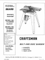
Save This Manual
For Future Reference
MODEL NO.
113, 225909
BELT AND DISC
SANDER ONLY
MODEL NO.
113.225931
BELT AND DISC
SANDER!WITH
LEGS AND MOTOR
Serial
Number
Model and serial
number may be found
at the right hand side
of the base,
You should record both
model and serial number
in a safe place for
CAUTION:
Read SAFETY
INSTRUCTIONS
carefully
BEL T AND D/SC SANDER
. assembly
® operating
o repair parts
Sold by SEARS, ROEBUCK AND CO., Chicago, iL. 60684 U.S.A.
Part No. 68073 Printed in USA

FULL ONE YEAR WARRANTY ON CRAFTSMAN BELT AND DISC SANDER
If within one year from the date of purchase th s Craftsman Belt and Disc Sander fails due to a defect in
material or workmanship, Sears will repair it, free of charge.
WARRANTY sERVICE IS AVAILABLE BY S MPLY CONTACTING THE NEAREST SEARS STORE
OR SERVICE CENTER THROUGHOUT THE UNITED STATES.
This warranty gives you specific legal rights, and you may also have other rights which vary from state to
state.
SEARS. ROEBUCK AND CO., Dept. 698/731A, Sears Tower, Chicago, IL 60684
general safety instructions power tools
1. KNOW YOUR POWER TOOL mask if cutting operation is dustv, and ear protectors
Read and understand the owner's manual and labels (plugs or muffs) during extended periods of operation.
affixed to the tool. Learn its application and limitations as
well as the specific potential hazards peculiar to this tool. 13. SECU RE WORK
2. GROUND ALL TOOLS
Th_s foot Is equIPbe(1 with an approved 3.conductor
cord and a 3-prong grounamg type plug tp fit the proper
groundmg type receptacle Th_ _reen conductor n the
cord _s tha grounding wire. Never connect the green w_re
_o a hve termmal.
3. KEEP GUARDS IN PLACE
- m working order, and in proper aolustment and align
ment
4. REMOVE ADJUSTING KEYS AND WRENCHES
Form habit of ¢heckmg to see tnat keys ana adlustmg
wrenches are removed from tool before turning _t pn
5. KEEP WORK AREACLEAN
C_uttereo areas and benches mwte acc_dems FtOol
must not be Slippery due tO wax or SaWdUSt
6. AVOID DANGEROUS ENVIRONMENT
Use clamps or a v_se to hold WOrK When Dractlcal It s
safer than uslng your 13and. frees both hands to operate
tool.
14. DON'T OVERREACH
Keep ProPer foottng and balance at all bmes
15. MAINTAIN TOOLS WITH CARE
Kee_) tools snaro and clean for best and safest perform
ance. Follow nstruct_ons for ubrlcat_ng ano changing
accessor les.
16. DISCONNECT TOOLS
before servicing, when changing accessories SUCh as
blades. P_ts. cutters etc
17. AVOID ACCIDENTAL STARTING
Make sure swdch s m "OFF" position before pluggmg
Ln
18. USE RECOMMENDED ACCESSORIES
Don't LISP Dower tOOlS in damp or wet locations or ex
Consult tbeowner's manua for recommended accessories.
(_se them to raln, Keep work area well hghted Provlde
d(lequate surrounding work space Follow the nslrucPons that accompany the accessories.
7. KEEP CHILDREN AWAY
All visitors should be keot a safed_stance from work area
8. MAKE WORKSHOP CHILD-PROOF
w_tn {_adlpcks rnastel swltche_ or r)V remownq starter
I<eVS
The use of mproDer accessories may cause hazards.
19. NEVER STAND ON TOOL
Serious ]nlury could OCCUI _f the tool _s tipper or tf the
cuttmg tool _s accidentally contacteP
Do not store materials 3bove or near the tool such mat
it s necessar, to stand on the tool to reach them
9. DON'T FORCE TOOL 20.
It wdl do the IOb bt, tter ana safer at the rate to{ which
• was des_qneo
10. USE RIGHT TOOL
_OCt't foFce too ol dttaci_mPnt to (30 a 1o13 r'[ was not
ties gnea for
11. WEAR PROPER APPAREL
Do not weal loose cIothlnh gloves, rleckttes or _ewelrv
brags. _.,rlstwatcnesl to get caugn[ in movlng parts
NONSLIP footwear s iecommended Weal protective 21.
nalr covering to contain long halt. Roll long Sleeves
above the elbow
CHECK DAMAGED PARTS
Before furmer use of the tool a guard or other _)art thai
_s Clamaged should be carefully checked to ensure that LI
will operate properly and perform its intended function
Check for alignment of mPvmg Darts bJndmg of mowng
baits, breakage of _arts, mountmg, and any other con
dd_ons that may affect ts operation. A guaro Ol othe_
oa_I that is damage(] should De properly repaired Ol
replaced
DIRECTION OF FEED
Feed work mto a blade or cutter aga nst the ChrPCtion Of
rotation of the blade or cutter only
12. USE SAFETY GOGGLES (Head Protection) 22. NEVER LEAVE TOOL RUNN NG
Wear safety goggles(must comply with ANSI Z87,1) at all UN ATTENDED
times. Everyday eyeglasses only have impact resistant Turn power off _)on't leave too_ unt_l t comps _o a
lenses, mey are NOT safety glasses. Also use face or dust coml)lete stop

safety instructions for beJt and disc sander
Safety is a combination of common sense, staying alert and
knowing how your belt and disc sander works. Read this
manual to understand this sander.
BEFORE USING THE SANDER:
WARNING: To avoid mistakes that could cause serious, per-
manent injury, do not plug the sander in until the following
steps are completed.
o Assembly. (See pages 7 - 16.)
o Learn the use and function of the ON-OFF switch,
backstop lock screw, belt adjusting screws, belt lock-
ing screws, work table and work table tilt lock screw.
(See pages 16 - 18.)
o Review and understanding of all safety instructions and
operating procedures in this manual.
" Review of the maintenance methods for this sander.
(See page 22.)
Read the following DANGER label found on the front of the
sander:
WHEN INSTALLING OR MOVING THE
SANDER.
AVOID DANGEROUS ENVIRONMENT. Use the sander in a
dry, indoor place protected from rain. Keep work area well
lighted.
Place the sander so neither the user or bystanders are forced
to stand in line with the abrasive belt or disc.
To avoid injury from unexpected sander movement:
e Put the sander on a firm level surface where there is
plenty of room for handling and properly supporting the
workpiece.
Support the sander so it does not rock.
Bolt the sander to the floor or work surface if it tends
to slip, walk, or slide during normal use.
To avoid injury or death from electrical shock:
o GROUND THE SANDER. This sander has an approved
3-conductor cord and a 3-prong grounding type plug.
Use only 3-wire, grounded outlets rated 120 volts, 15
amperes (amps). The green conductor in the cord isthe
grounding wire. To avoid electrocution, NEVER connect
the green wire to a live terminal.
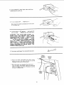
,, Make sure your fingers do not touch the plug's metal
prongs when plugging or unplugging the sander.
To avoid back injury, get help or use recommended casters
when you need to move the sander. Always get help if you
need to lift the sander.
NEVER STAND ON TOOL. Serious injury could occur if the
tool tips or you accidentally hit the cutting tool. Do not store
anything above or near the tool where anyone might stand
on the tool to reach them.
BEFORE EACH USE:
Inspect your sanderl
DISCONNECTTHE SANDER. To avoid injury from accidental
starting, unplug the sander, turn the switch off and remove
the switch key before changing the setup, sanding disc or
belt or adjusting anything.
CHECK DAMAGED PARTS. Check for:
,, alignment of moving parts,
,, binding of moving parts,
= broken parts,
• stable mounting, and
o any other conditions that may affect the way the sander
works.
WARNING: The 2-1/2" machine pulley and the 2" motor
pulley furnished will run the disc at about 2700 RPM and the
belt at about 2100 FPM (Feet Per Minute) when used with a
3450 RPM motor. To avoid throwing of work or broken
sander fragments, never substitute or interchange these
pulleys to increase this speed.
If any part is missing, bent, or broken in any way, or any elec-
trical parts don't work properly, turn the sander off and
unplug the sander. REPLACE damaged, missing, or failed
parts before using the sander again.
MAINTAIN TOOLS WITH CARE. Keep the sander clean for
best and safest performance. Follow instructions for lubri-
cating.
REMOVE ADJUSTING KEYS AND WRENCHES from tool
before turning it on.
To avoid injury from jams, slips or thrown pieces:
• USE ONLY RECOMMENDED ACCESSORIES. (See
page 22.) Consult this Owner's manual for recom-
mended accessories. Follow the instructions that
come with the accessories. The use of improper ac-
cessories may cause risk of injuryto persons.
Adjust table to clear the sanding surface by no more
than 1/16 of an inch.
,, Make sure all clamps and locks are tight and no parts
have excessive play.
• KEEPWORK AREA CLEAN. Cluttered areas and benches
invite accidents. Floor must not be slippery.
To avoid burns or other fire damage, never use the sander
near flammable liquids, vapors or gases.
Plan ahead to protect your eyes, hands, face, ears.
KNOW YOUR SANDER. Read and understand the owner's
manual and labels affixed to the tool. Learn its application
and limitations as well as the specific potential hazards pecu-
liar to this tool.
To avoid injury from accidental contact with moving parts,
don't do ]ayout, assembly, or setup work on the sander while
any parts are moving.
AVOID ACCIDENTAL STARTING. Make sure switch is "OFF'"
before plugging sander into a power outlet.

safety instructions for belt and disc sander
Plan your work. , • Use extra supports (tables, saw horses, blocks, etc.) for
USETHERIGHTTOOL Don t forcetoo[or attachment to doa any workpieces large enough to tip when not held down
job it was not designed to do. to the table _oD,
CAUTION:Thismachineisnotdesignedforheavydeburring • NEVER use another person as a substitute for a table
operations. When finishing metals, sparks or hot fragments extension or as additional support for a workplace that
could cause a fire. To avoid this. disconnect any dust col- is longer or wider than the basic sander table, or to help
feed support or pull the workp=eca,
lectieg hose fromthesander. Also, remove all traces of wood
dustfrom inside dust traps in the sander. = When finishing on the Disc, always press the workpieca
against the "'Down" side of the disc. Sanding against the
Dress for safety, side coming up from under the table could damage the
work by making it "chatter," or tear the work from your
WEAR YOUR hands and throw it.
Any powersandercan throw foreignobjects intothe eyes. This
can cause permanent eye damage. Wear safety goggles (not
glasses) that cornpty withANSI Z87.1. Everyday eyeglasses
have only impact resistant lenses. Theyare not safety glasses.
Safety goggles are available at Sears retail catalog stores.
Glasses or goggles not in compliance with ANSI Z87.1 could
seriously hurt you when they break,
= Do not waarioosa clothing, gloves, neckties or jewelry
(rings. wrist watches). Tney can get caught and draw
you into moving parts.
= Wear nonslio footwear.
- Tie back long hair.
• Sand only one workpiece at a time,
• Clear everything except the workoiece and related sup-
port devices off the table before turning the sanaer on.
Plan the way you will hold the workpiece from start to finish.
Avoid awkward oeerations and hand positions where a sud-
den slip could cause fingers or hand to move into a sanding
surface. Keep fingers away from where the belt goes into the
dust trap,
DON'T OVERREACH. Keep good footing and balance
Keep your face and booy to one side. out of line with a pos-
sible throwback
WHENEVER SANDER IS RUNNING.
WARNING: Don't let familiarity (gained from frequent use of
your belt and disc sander} cause a careless mistake. A care-
less fraction of a second is enough to cause a severe injury.
Before starting your cut, watch the sander while it runs. If it
makes an unfamiliar noise or vibrates alot, stop immediately.
Turn the sander off. Unplug the sander. Do not restart until
finding and correcting tee problem.
• Roll long sleeves above the elbow. Make sure the sanding disc turns counterclockwise before
- Noise levels vary widely. To avoid possible hearing dam- using the sander.
age, Wear ear plugs ormuffs when using sander for hours KEEP CHILDREN AWAY. Keep all visitors a safe distance from
at a time. the sander. Make sure bystanders are clear of the sander and
o Sanding operationaare usually dusty. Wear a dust mask workpiece.
along with the safety goggles. DON'T FORCE TOOL. It will do the job better and safer at its
Inspect your workpieoe, designated rate. Press the workeiece against the sanding
Make sure there are no nails or foreign objects in the part of material only hard enough to let it sand without bogging
the workDiece to be sanded, down or binding.
Before freeing any jammed material:
Plan your work to avoid THROWBACKS--when the work-
piece catches on the sanding belt or disc and is torn from
your hands.
• Make sure there's no debris between the workpiece and
its supports.
• When sanding irregularly shaped workpiecas, plan your
work support so it wit{ not slip and be pulled from your
hands.
• Turn switch "ORE"
• Unplug the sander.
• Wait for all moving parts to stop.
To avoid throwback of the workpiece, use work!_iece supports
for all flat surface sanding.
BEFORE LEAVING THE SANDER:
• Use extra caution with large, very small or awkward
pieces:
• Never use this tool to finish pieces too small to hold by
hand.
Wait for all moving parts to stop,
Make workshop child-proof. Lock the shoo. Disconnecl
master switches. Remove the yellow switch key Store it
away from children and others not qualified to use tne tool.

electrical requirements
CONNECTING TO POWER SOURCE OUTLET
This machine must be grounded while in use to protect
the operator from electric shock.
Plug power cord into a 120V properly grounded type outlet
protected by a 15-amp. dual element time delay or Circuit-
Saver fuse or circuit breaker.
If you are not sure that your outlet is properly grounded,
have it checked by a qualified electrician.
WARNING: DO NOT PERMIT FtNGERSTO TOUCH THE
TERMINALS OF PLUGS WHEN INSTALLING OR RE-
MOVING THE PLUG TO OR FROM THE OUTLET.
WARNING: IF NOT PROPERLY GROUNDED THIS
POWER TOOL CAN INCUR THE POTENTIAL HAZARD
OF ELECTRICAL SHOCK. PARTICULARLY WHEN USED
IN DAMP LOCATIONS IN PROXIMITY TO PLUMBING.
IF AN ELECTRICAL SHOCK OCCURS THERE IS THE
POTENTIAL OF A SECONDARY HAZARD SUCH AS
YOUR HANDS CONTACTING THE ABRASIVE BELT
OR DISC.
If power cord is worn or cut, or damaged in any way, have
it replaced immediately.
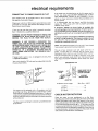
Your unit is wired for 120 volts and has a plug that looks like
the one shown below.
PROPERLY
GROUNDED
OUTLETs, 4
/n Ul
/Do l
\/
3-PRONG
PLUG
GROUNDING
PRONG
If the outlet you are planning to Use for this power tool is
of the two prong type DO NOT REMOVE OR ALTER
THE GROUNDING PRONG IN ANY MANNER, Use an
adapter as shown and always connect the grounding lug to
known ground.
It is recommended that you have a qualified electrician
replace the TWO prong outlet with a properly grounded
THREE prong outlet.
A temporary adapter as shown below is available for
connecting plugsto 2-prong receptacles. The green ground-
ing lug extending from the adapter must be connected to a
permanent ground such as to a properly grounded outlet
box,
A temporary adapter as illustrated is available for connecting
plugs to 2-prong receptacles. The temporary adapter should
be used only until a properly grounded outlet can be
installed by a qualified electrician.
NOTE: The adapter illustrated is for use only if you already
have a properly grounded 2-prong receptacle.
The use of any extension cord will cause some loss of
power. To keep this to a minimum and to prevent over-
heating and motor burn-out; use the table below to deter-
mine the minimum wire size (A.W.G.) extension cord. Use
only 3 wire extension cords which have 3-prong grounding
type plugs and 3-pole receptacles which accept the tools
plug.
GROUNDING LUG
I _ MAKE SURE THIS IS
3-PRONG _ _ I _ " j} CONNECTED TO A
__.,,,_r__..._3_ [_ ]1 2-PR ONG
/ _ RECEPTACLE
ADAPTER
Extension Cord Length
Wire Size A.W.G.
This power tool is equipped with a 3-conductor cord and
grounding type plug, approved by Underwriters' Labora-
tories and the Canadian Standards Association. The ground
conductor has a green jacket and is attached to the tool hous=
ing at one end and to the ground prong in the attachment plug
at the other end.
This plug requires a mating 3-conducto{ grounded type out-
let as shown.
0-25Ft ................... 16
26-50Ft ................... 14
51-100 Ft .................. 12
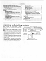
CHECK MOTOR ROTATION
Place the motor on your workbench or on the floor.
Standing clear of the motor shaft, plug the motor cord into a
properly grounded outlet. Notice the rotation of the shaft.
As you look directly at the motor shaft it should be turning in
the counterclockwise direction _ . tf the motor shaft is
turning counterclockwise, remove the plug from the power
outlet and continue the assembly procedures. If the motor is
turning clockwise, remove the plug from the power outlet
and contact your Sears Store immediately,
5

CONTENTS
SAFETY INSTRUCTIONS FOR POWER TOOLS .............. 2
ADDITIONAL SAFETY NSTRUCTIONS FOR BELT AND
DISC SANDER ............................................................ 3
ELECTRICAL REQU REMENTS .......... 5
Check Motor Rotation .............................................. 5
UNPACKING AND CHECKING CONTENTS ...................... 6
ASSEMBLY ....................................................................... 7
Assembling Steel Legs ............................................... 8
Mounting Belt and Disc Sander on Steel Leg Set ...,.. 8
Installing Sanding Disc and Dust Trap ....................... 9
Installing Motor, V-Belt Tensioning and Tracking .... 1!
On-Off Switch ........................................................... 12
Installing Work Table ............................................... 14
Installing Abrasive Belt Tensioning and Tracking .... 14
Installing Belt Dust Trap ........................................... 15
Installing Backstop ..................................... 16
GETTING TO KNOW YOUR SANDER ............................. 16
Belt Adjusting Screws ............................................. 17
Belt Locking Screws ................................................. 17
Work Table Tilt Lock Screw ..................................... 17
Backstop Lock Screw ............................................... 18
Belt Table Locking Bolts .......................................... 18
Belt Table Stop ......................................................... 18
BASIC OPERATION ......................................................... 19
Surface Finishing on tne Abrasive Belt ................... 20
End Finishing on the Abrasive Belt .......................... 20
Finishing Curved Edges on the Abrasive Belt .......... 21
Finishing Small End Surfaces and Curved Edges
on Disc ................................................................ 21
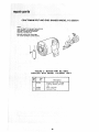
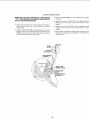
MAINTENANCE ................................................................ 22
Motor Maintenance and Lubrication ......................... 22
LUBRICATION .................................................................. 22
Recommended Accessories .................................... 22
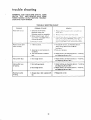
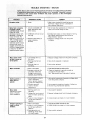
TROUBLESHOOTING ...................................................... 23
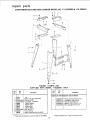
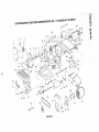
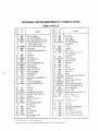
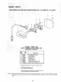
REPAIR PARTS ................................................................ 25
Motor Connections ................................................... 29
unpacking and checking
Model 113.225900 Belt and Disc Sander is shipped
complete in one carton but DOES NOT INCLUDE Steel
Legs or Motor.
Model 113.225931 Belt and 0isc Sander is shipped
complete in one carton and INCLUDES Steel Legs and
Motor.
Separate all parts from packing materials and check each"
item with Ilustration and "Table of Loose Parts." Make
certain all items are accounted for, before discarding any
packing material.
contents
If any parts are m_ss_ng, do not attempt to assemble the
Belt and Disc Sander. plug in the power core. or _urn the
switch on until the missing parts are obtained aria
installed correcti V.
TOOLS NEEDED - - - ,
3/4"7/16"1/2"WrenchWrenChwrenchMedium_:2Screwdriver_PhilbpsScrewdrlvelC°mbinati°nSquare !i_._Square
3/8" Wrench
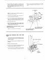
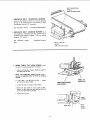
COMBINATION SQUARE MUST BE TRUE.
DRAW LIGHT J 8OAR° 3/4 THICK
LINE ON BOARO TNIS EDGE MUST B£
AEOf_G THIS EIE)GE I_'_ _ PERFECTLY STRAIGHT
I "N.I
[ q_u
Using a 112" wrench, remove the plywood attached to
the machine. Save the nuts and bolts and washers. You SHOULD_ NOGAPOROVE,LAPNEREWHEN
Wil] need them for attaching the machine to the base SOUARES_L'PPEOOVE"_NDOTTEOPOS,T_ON
6

O
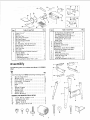
Item ! Table of Loose Parts Qty, j
A V-Belt, 1/2 x 41" . ....................... 1
B Backstop ............................... 1
O Belt, Du_t Trap .......................... 1
D Motor Pulley Belt Guard ................... 1
E Belt Guard Support ....................... 1
F Belt Guard Support Bracket ................ I
G "S'" Clip ............................... 3
H Pan Head Screw, Type 23, 10-32 x 1/2 ........ 3
J Baseand Belt, Table (w/Sanding Belt) ......... t
K Disc Dust Trap .......................... t
L Oust Trap Cover ......................... 1
M Work Table ............................. 1
N Bag (containing the following loose parts)
(Part No. 68035)
Motor Pulley, 2 In. Oia................... 1
Wrench, 1/2" . ......................... 2
5/32 Setscrew Wrench ................... 1
Flat Head Machine Screw 10-32 x 1-3/4 ...... 4
D E
Item Table of Loose Parts Qty.
Pan HeadScrew, Type 23 8-32 x 3/8 ......... 5
Fiat Washer, 21/64 x 7/8 x 1/8 .............. 1
Hex, Head Machine Screw 5/16-18 x 1 ........ 1
Screw, M Pan Hd. 10-32 x 9/16 ............. I
Lockwasher No, 10 Int. Tooth .............. 1
Hunger, Cable ........................... 1
0 Owner's Manual ........................... t
P 9" Abrasive Disc .......................... 1
Q Sanding Disc (w/Set Screw) .................. 1
R Belt,Sanding .............................. 1
- Bag Assembly, Outlet (Part No. 68064)
(Containing the following loose parts):
S Outlet, on/off Power ...................... 1
T Switch Key ............................. 1
U Bracket, Switch Mounting .................. t
V Screw, Pan Hd. 8 x 3/8 .................... 3
W Lockwasher, 114" . ....................... 2
X Screw; Pan Hd. Machine 1/4-20 x 1/2 ......... 2
assernbJy
The following parts are included with Model 113.225931
ONLY.
Item
No. Qty.
*Loose Parts Bag Part#68062Containing Following items:
*A Nut, Hex Head1/2-13 ........................ 8
*A Nut Hex 1/4-20 .............................. 32
*B Screw Truss Hd. 1/4-20x 5/8 ................. 32
*C Lockwasher, 1/4 External .................... 32
*D Foot, Leveling .............................. 4
E Motor ...................................... 1
F Leg ......................................... 4
G Channel,Support ........................... 2
H Stiffener, Side .............................. 2
J Stiffener, End ............................... 2
K Support, Motor ............................. 1
P Bracket, Mounting ........................... 1
HAROWABEFORMOUNTINGTOOL& MOTOR
*L Screw,Hex Hd.5/16-18x 1-1/2 ............... 2
*C Lockwasher Ext. 5/16 ....................... 6
*A Nut,Hex 5116-18 ............................ 6
*M Washer11132ID ............................ 6
*N Bolt, Carriage 5116-18x 314 .................. 4
D
E
F•
L
H
K
N P

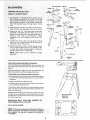
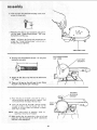
1. Assemble the two (2) End Stiffeners and the two 2
Side Stiffeners using four (4) 1/4-20 Truss head
screws. The End Stiffeners are placed On top of each
Side Stiffener as shown. Insert screws through the
9/32 inch diameter holes and finger tighten 1/4-20
nutS.
2. Attach the four (4) legs to the side and End Stiffener
using 1/4-20 screws, Iockwashers and nuts as shown.
3. Remove the four (41 Truss head screws which were
assembled in Paragraph No. One. Place the two (2
Support Channels as shown, in position align holes in
supports with holes in the Stiffeners, replace
Iockwashers and nuts, Tighten all nuts using 7/16
wrench.
4. Assemble the motor support to steel legs with 1/4-20
screws and nuts. Motor support can be mounted to
either end of stand. Tignlen nuts
5. Install leveling feet as shown. To level Leg Set, loosen
nut on inside of leg and turn nut on outside to raise
or lower feet. Adjust alt four levelers, if necessary,
and then tighten nuts on inside of leg.
NOTE: These levelers are not intended for height
adjustment.
END STIFFENER HEX NUT
SCREW_ 1 | LOCKWASHER
S,DE ST,FFEN R
STIFFENER
SIDE STIFFENER
LOCKWASHER
\
HEX NUT _e
_ CH/%NNEL
.r
_- _ SUPPORT
_ k _.
LEG
/
SCREW
\
CHANNEL
SUPPORT
MOTOR
SUPPORT
/ NUT
LOCKWASHER
LEG
SCREW
WHEN INSTALLING OR MOVING THE SANDER.
AVOID DANGEROUS ENVIRONMENT, Use the sander n a
dry, indoor place protected from rain. Keen work area well
lighted.
Place the sander so neither the user nor bystanders are
forced to stand in line with the abrasive belt or d sc.
To avoid injury from unexpected sandel movement:
= Put the sander on a firm level surface where there is plenty
of room for handling and properly supporting the
workpiece.
- Support the sander so it does not rock.
,,Bolt the sander tothe floor or work surfaceif it tends to slip,
walk. or slide during normal use.
To avoid back injury, get help or use recommended casters
when you need to move the sander. Always get help if you
need to lift the sander.
NEVER STAND ON TOOL. Serious injury could occur if the
too] tips or you accidentally hit the cutting tool, Do not store
anything above or near the toot where anyone might stand on
the tool to reach them.
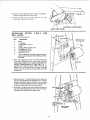
MOUNTING BELT AND DISC SANDER ON
CRAFTSMAN STEEL LEG SET.
CATALOG NO. 9-22236
NOTE: Forillustrative purposes, the Belt and Disc Sander is
shown mounted on the Craftsman Catalog No. 9-22236
Steel Leg Set. This Leg Set is included with Model No.
113.225931.
#
MOTOR MOUNT
BRACKET
THISSIDE
0 C OOc
o°o°
o o
___c oc

1. )lace the 3elt and Disc Sander on the Steel Legs,
position as shown, ane align the mounting qoles n
the feet of the Belt and Disc Sander with those in the
END STIFFENERS marKea with an X n tne
Jllustratior !.
2. Mount to legs using two 5_16-18 x 2-1/2'" hex head
screws, flat washers, externa! Iockwashers. ana hex
nuts.
NOTE: The abrasive belt is shipped detached. To
install the belt on the machine:
1. Loosen both belt LOCKING screws, using the 1/2"
wrench furnished with the machine.
2. Turn both of the abrasive belt AJUSTING screws as
shown until they stop. Retighten the two belt LOCK-
ING screws so that the idler pulley does not come out
3. Remove the piece of paper,
4. Remove the protective coating, that is applied at the
factory, from the belt table. Use any ordinary house-
hold type grease and spot remover.
WARNING: Never use gasoline, naptha, or similar
highly volatile solvents.
NOTE: Do not apply wax to the belt table.
1/2" WRENCH
/
BELT ADJUSTING SCREW
(ONE ON EACH SIDE)
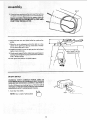
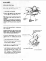
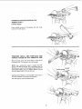
INSTALLING SANDING DISC AND DUST
TRAP
1. Loosen the belt table locking bolts behind the mount-
ing bracket using one of the 1/2"" wrenches supplied
with your machine.
2. Position belt table vertically and tighten only one of
the bolts.
3. Place the V-Belt over the pulley.
4. Attach the switch assembly to the base using the two
screws and washers packed with the switch.
5. Loosen the bolt that you tightened in step 2. Position
the belt table horizontally, and tighten both bolts.
BELT TABLE LOCKING
WRENCH
SWITCH
ASSEMBLY

assembly
B. Find five 378" Pan Head Self-Treading screws from
among the loose parts.
7. Place Disc Dust Trap on your workbench and screw m
five Pan Head "Thread Cutting Screws," 3/8" long.
Screw them in all the way.
NOTE: The holes in the Trap are not threaded but the
screws are "Thread Cutting Screws" and will cut a
thread as they are tightened.
DISC DUST TRAP
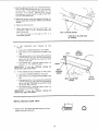
R. Find four Flat Head Machine Screws 1-¾" long from
among the loose _arts
FLAT HEAD SCREWS
1 3/4" LONG
FLAT SPOT
/ONSHAFT
/
/
/
9. Attach the Disc Dos1 Trap with four flat head screws
!-¾" long.
10. There is a flat spot on the shaft near the end. Rotate
the shaft so that the flat spot is facing up.
/
/ /
11 Place the disc on the shaft so that the set screw ts
facmc up. Position the disc so that it is approx, 1/16
rich outward from the edge of the dust trap.
12 Insert the long end of me 532" setscrew wrench
through me hole in the disc housmg and mto the
setscrew n the disc. Make sure setscrew _s aligned
with "F ]at" on shaft.
TRAP
NOTE: After several hours of operation, check for
ooseness of setscrew and ret_gh[er
13. Make certain that the metal disc is free of oil and
grease then peel the backing from the 9" abrasive disc
and affix to the sanding disc.
5/32INCH
/--SETSCREW
/ WRENCH
\ \
\
10

14. Remove the top right hand screw which VOU installed in
step 6 and loosen the other t_ree screws.
15. Install the Dust Trap cover and reD,ace me too right
hand screw. Tighten ag five screws.
TOP RIGHT HAND SCREW
DUST TRAP COVER
iNSTALLING MOTOR, V-BELT,
BELT GUARD
1. Locatethefollowingparts:
OTY. Description
1
1
1
1
4
4
4
4
Motor
"L" Bracket
Pulley (approx. 2" Dia.)
V-Belt
Carriage Bolt 5/16-18 x 3/4
Flat Washer 5/16 I.D.
Lockwasher 5/16 I.D.
Hex Nut 5/16-18
AND
Guard Assembly including a guard support,
guard support bracket, self-threading screws,
and clips.
2. Place motor against the motor mounting bracket and
insert bolts through holes in motor base and then
through holes marked "X" in motor mounting bracket.
DO NOT TIGHTEN BOLTS AT THIS TIME. The "'L"
bracket which holds the guard support must be slid
between the motor base and the motor mounting
bracket so motor must be loosely assembled to bracket
at this time.
II
LOCKWASHER
CARRIAGE BOLT
5/t6-18 x 3/4
/
MOTOR
3. Slide long leg of "L" bracket between motor base and
motor mounting bracket. Then sandwich the "L" bracket
between the guard support bracket and the guard
support and fasten together with self-threading screws
as shown. Install clips onto belt guard support.
4. Install the 2" pulley onto the motor shaft flush with the
end of the shaft and tighten the set screw in the pulley
hub against the flat part of the motor shaft.
TWO HOLES
TOGETHER
CLIPS
BELT GUARD
SUPPORT BRACKET
10-32 X 1/2 IN,
SELF-THREADING'
SCREW
/_ BELT GUARD
SUPPORT
11

assembly
5. Placebelt overmachine pulleyand insert the belt nl
the openend oftheguard andoutthe roundopening.
MAKE SURE BELT HAS NOT SLIPPED OFF OF
MACHINE PULLEY FROM STEP 3, DISC AND
DUST TRAP INSTALLATION.
/
/
BELT
6. Place the bolt onto the motor pulley by rotating the
pulley,
7. Move the motor sideways so that the belt is in the
center of the opening in the top of the base. Visually
line up the pulleys and V-belt.
8. PUSH downward on motor to apply tension to belt and
tighten motor bolt nuts.
9. Check guard support before tightening guard support
screws. Guard support must becentered around motor
shaft, Tighten screws.
10. Push guard into position on guard support.
r •
I
/ /
/
IELT MUST BE ON
MACHINE PULLEY
ON-OFF SWITCH
WARNING: DON'T CONNECT POWER CORD TO
ELECTRICALOUTLET IN YOU R SHOP UNTIL YOU ARE
SURE MOTOR ROTATION IS CORRECT. SEE PAGE 5,
The On-Off Switch has a locking feature. THIS FEATURE IS
INTENDED TO PREVENT UNAUTHORIZED AND POSSIBLE
HAZARDOUS USE BY CHILDREN AND OTHERS.
1. Insert key into switch, _
NOTE: Key is made of yellow plastic
12

2.Toturnmachineon.insertfingerunder switch lever
and pull end of switch out,
3. TO turn machine OFF , . . PUSH lever in.
Never leave the machine unattended until it has come
to a complete stop,
4. To lock switch in OFF position . . . hold switch IN
with one hand . . . REMOVE key with other hand.
WARNING: FOR YOUR OWN SAFETY, AL-
WAYS LOCK THE SWITCH "OFF" WHEN
MACHINE IS NOT IN USE . .. REMOVE KEY
AND KEEP IT IN A SAFE PLACE . . . ALSO
• . . IN THE EVENT OF A POWER FAILURE
(ALL OF YOUR LIGHTS GO OUT) TURN
SWITCH OFF.•. LOCK ITAND REMOVE THE
KEY. THIS WILL PREVENT THE MACHINE
FROM STARTING UP AGAIN WHEN THE
POWER COMES BACK ON.
5. Find plastic cable hanger from among the loose parts.
6. Route the motor cord behind the motor mount,
across the top of the base and plug it into the
receptacle in the side of the switch box,
7. Bring the power cord alongside the motor cord . . .
wrap the plastic cable hanger around the cords and
attach the hanger to the top of the base by pushing
i_ into a _" diameter hole.
CABLE
HANGER
POWER
CORD
MOTOR
CORD
13

INSTALLING WORK TABLE
NOTE: Apply coat of paste wax ;o the work table.
This will make it a little easier to feed the work.
1. Loosen the table positioning screw.
2. Insert the table support rod in the hole in the base
until the edge of the table is approximately 1/16"
from the abrasive disc, Tighten the screw.
NOTE: There is asecond mounting hole in the base. This
is for mounting the table when the belt is used in a ver-
tical position.
WARNING: To avoid trapping the work or fingers be-
tween the table and sanding surface, the table edge
should be a maximum 1/16 inch from the sanding
surface, the table should be completely engaged on
the rod.
/
SECOND
MOUNTING
HOLE TABLE
POSITIONING
SCREW
\
TABLE
SUPPORT
ROD
INSTALLING ABRASIVE BELT-TENSIONING
AND TRACKING
WARNING: FOR YOUR OWN SAFETY, TURN
SWITCH "OFF" AND REMOVE PLUG FROM
POWER SOURCE OUTLET BEFORE REMOV-
ING OR INSTALLING ABRASIVE BELT.
On the smooth side of the abrasive belt you will find a DIRECTIONAL ARROW\
•dl"r - n ,
ectlonal arrow. The abras ve belt must run _,
in the
direction of this arrow so that the splice does not come
apart.
1. Loosen the two abrasive belt LOCKING screws.
2. Place the abrasive belt over the pulleys with the direc-
tional arrow pointing as shown. Make sure the abra-
sivebelt iscentered on both pulleys.
Turning the abrasive belt ADJUSTING screws will cause
the idler pulley to move in or out. When the idler pulley
is moved outward, it puts TENSION on the belt.
3. Place both of the ½" wrenches on the ADJUSTING
screws and pull the wrenches toward you. This will
stretch the abrasive belt. Move the wrenches back and
forth a few times so that you "'get the feet" of the
abrasive belt while it is stretching (TENSIONING).
/
BE LT ADJUSTING SCREWS
Apply a small amount of TENSION to the abrasive
belt by pulling the wrenches toward you, so that the
TENSION feels the same on both wrenches.
PULL WRENCHES IN THIS
DIRECTION TO APPLY
TENSION
BELT LOCKING SCREW
14

4. Hold the abrasive disc with your left hand tO keep it
from turning while pushing the belt in the direction
of the arrow. If the abrasive belt slips over the
pulleys, turn both ADJUSTING screws
simultaneously a small amount to apply a little more
tension to the abrasive belt.
5. Adjust the tension so that the abrasive belt does not
slip very easily when pushing it, while you are holding
the disc.
6. Tighten the locking screws,
7. Plug in the power cord. Turn the switch "ON", and
immediately "OFF", noting if the belt moved to the
right or to the left.
If it did not move to the right or left, it is
TRACKING properly.
\
BELT LOCKING SCREW
PUSH BELT IN DIRECTION
OF ARROW
8. IF THE ABRASIVE BELT MOVES TO THE
RIGHT:
a. Loosen the LOCKING SCREWon the RIGHT.
b, Place wrenc, h on the ADJUSTING SCREW on the
right.
c. Push abrasive belt so it is moving while pulling the
wrench toward you. This will move the abrasive
belt to the left. PUSHING the wrench will move
the belt to the right.
d. The abrasive belt is tracking properly when it is
centered on the DRIVE pulley.
IMPORTANT: If you have difficulty tracking the
abrasive belt, apply more tension.
9. IF THE ABRASIVE BELT MOVES TOTHE LEFT:
a. Loosen the LOCKING SCREW on the LEFT.
b. Place wrench on the ADJUSTING SCREWon the
left.
c. Push abrasive belt so it is moving while pulling the
wrench toward you, This wilt move the abrasive
belt to the right. PUSHING the wrench will move
the abrasive belt to the left.
d. The abrasive belt is tracking properly when it is
centered on the DRIVE pulley.
IMPORTANT: If you have difficulty tracking the
abrasive belt, apply more tension,
RIGHT
BELT
LOCKING
SCREW
LEFT
BELT ADJUSTING
SCREW
BELT
MOVING
TO RIGHT
DRIVE
PULLEY
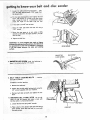
INSTALLING BELT DUST TRAP
1. Find one 10 - 32 x 9/16" Pan Head screw and a lock-
washer among the loose parts.
©
15

assembWy
2. Attach the dust trap . make surethe top edge is
below the surface of the abras ve be t
PAN HEAD SCREW
AND LOCKWASHER E3ELT DUST TRAP
INSTALLING BACKSTOP
1. Find one 5/16" x 1" Hex. Head bolt and one fiat
washer among the loose parts.
2. Place the washer on the bolt. and screw it halfway
into the mounting hole. Place the backstoo into pos-
tion and tighten the bolt. When removing the bacK-
stop, loosen the bolt but do not remove it,
BACKSTOP BACKSTOP
LOCK SCREW
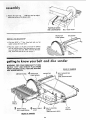
getting to know your belt and
WARNING: FOR YOUR OWN SAFETY TURN
SWITCH "OFF" AND REMOVE PLUG FROM
POWER SOURCE OUTLET BEFORE MAKING
ANY AOJUSTM ENTS.
LOCK SCREW
\
\
\
BACKSTOP
disc sander
BACK OF SANDER
BELT ADJUSTING
SCREW
(ONE ON EACH SIDE)
WORK
TABLE
WORKTABLE
TILT LOCK SCREW
/
/
/
6 BELTTABLE 2 BELT_OC_'_G
STOP SCREW
(ONE ON EACH SIDE)
FRONT OFSANDER
\
IDLER
PULLEY
16

BELT ADJUSTING
SCREW
(ONE ON EACH SIDE)
1. ABRASIVE BELT ADJUSTING SCREWS
cause the idler pulley to move in or out for applying
tension to the abrasive belt or for tracking it. They
are adjusted using the 1/2" wrenches,
See "Assembly" section... "Installing Abrasive Belt".
2. ABRASIVE BELT LOCKING SCREWS lock
the adjustment mechanism after the abrasive belt is
tensioned and tracking properly, They are locked
using the 1/2" wrench.
See "assembly" section . . . "Installing Abrasive
Belt".
BELT LOCKING
SCREW
(ONE ON EACH SIDE)
3,
WORK TABLE TILT LOCK SCREW locks
the table. It islocked using the 1/2" wrencn.
a. Using a combination square, check the angle of
the table with the disc.
NOTE: The :ombination square must be "true"--
See start of assembly section on Pg. 6 for checking
method.
b. If the table Js not 90 ° with the disc.., loosen
tilt Ic_ck screw and ti t table,
c. Loosen the lock nut using a 7/16" wrench.
d. Screw the atop screw in or out. using a 3/8""
wrench so that when the table touches the stop
screw, the table is 90° to the disc.
e. Tighten the lock nut
/
TABLE POSITIONING
LOCK SCREW
\
TABLE 1/2"
FROM DISC
LOCK NUT
STOP
SCREW
_" TILT
LOCK
SCREW
17

" rge ng to know you belt and disc
f Loosen the table positioning lock screw., . posi-
tion the table approximately 1/16" awa_ from
the abrasive disc.
g. Tilt the table downward but don't tighten the ock
screw, and position it as close to the disc as pos-
sibte. Using the head of a combination square,
check the angle of the table with the disc,
h. If the table is not 45 ° with the disc:
sander
/
i. Raise the table and loosen the lock nut using a
7/16" wrench.
j, Screw the stop screw in or out, using a 3/8'"
wrench so that when the table touches it, it is 45 °
with the disc.
k. Tighten the lock nut.
WARNING: To avoid trapping the work or fingers
between the table and sanding surface, the table must
be repositioned on the rod to maintain a maxtmum
1/16 inch space between the table and sanding
surface,
STOP SCREW
4. BACKSTOP LOCK SCREW locks the backstop in
place. It is locked u_ing the 1/2"' wrench,
BACKSTOP
LOCK SCREW
\
BACKSTOP
5. BELT TABLE LOCKING BOLTS ... lock the
belttable in position.
To adjust to vertical position:
a. Remove the backstop.
b. Loosen the two belt table locking bolts using the
1/2" wrench supplied with your machine.
c. Position belt table vertically and tighten the two
bolts.
6, ABRASIVE BELT TABLE STOP can be adj-
usted so that the abrasive belt table is level with
the floor when in a horizontal position.
a, Loosen the lock nut using a 3/4"" wrench.
BELT TABLE
LOCKING BOLT/
b, Place a level on the abrasive belt table and using a
314" wrench, screw the stop bolt in or out until
the table is level.
LOCK NUt
STOP BOLT
18

basic operation
BEFORE USING THE SANDER:
WARNING: Toavoid mistakes that could cause serious, per-
manent injury, do not plug the sander in until the following
steps are completed.
o Assembly. (See pages 7 - 16.)
" Learn the use and function of the ON-OFF switch,
backstop lock screw, belt adjusting screws, belt bcking
screws, work table and work table tilt lock screw. (See
pages 16- 18,)
o Review and understanding of all safety instructions and
operating procedures in this manual.
o Review of the maintenance methods for this sander,
(See page 22.)
BEFORE EACH USE:
Inspect your sander.
DISCONNECT THE SANDER. To avoid injury from accidental
starting, unplug the sander, turn the switch off and remove
the switch key before changing the setup, sanding disc or
belt or adjusting anything.
CHECK DAMAGED PARTS. Check for:
e alignment of moving parts,
• binding of moving parts,
• broken parts,
• stable mounting, and
t any other conditions that may affect the way the sander
works.
If any part is missing, bent, or broken in any way, or any
electrical parts don't work properly, turn the sander off and
unplug the sander. REPLACE damaged, missing, or failed
parts before using the sander again
MAINTAIN TOOLS WITH CARE. Keep the sander clean for
best and safest performance. Follow instructions for lubri=
caring.
REMOVE ADJUSTING KEYS AND WRENCHES from tool
before turning it on.
To avoid injury from jams, slips or thrown pieces:
• USE ONLY RECOMMENDED ACCESSORIES. (See
page 22.) Consult this Owner's manual for recommended
accessories. Follow the instructions that come with the
accessories. The use of improper accessories may
cause risk of injury to persons.
= Adjust table to clear the sanding surface by no more than
1/16 of an inch.
• Make sure all clamps and locks are tignt and no parts have
excessive play.
= KEEP WORK AREA CLEAN. Cluttered areas and benches
invite accidents, Floor must not be slippery.
To avoid burns or other fire damage, never use the sander
'lear flammable liauids, vapors or gases.
Plan ahead to protect your eyes, hands, face, ears.
KNOW YOUR SANDER. Read and understand the owner's
manual and labels affixed to the tool, Learn its application
and limitations as well as the specific potential hazards pecu-
iar to this tool.
To avoid injury from accidental contact with moving parts,
don't do layout, assembly, or setup work on the sander while
any parts are moving.
AVOID ACCIDENTAL STARTING. Make sure switch is " OFF"
before plugging sander into apower outlet.
Plan your work.
USE THE RIGHTTOOL. Don't force tool or attachment to do a
job it was not designed to do.
CAUTION: This machine is not designed for heavy deburring
operations, When finishing metals, sparks or hot fragments
could cause a fire. To avoid this, disconnect any dust col-
lecting hose from the san der. Also, remove all traces of wood
dust from inside dust traps in the sander.
Dress for safety.
Any power sander can throw foreign objects into the eyes. This
can cause permanent eye damage. Wear safety goggles (not
glasses) that comply with ANSI Z87.1. Everyday eyeglasses
have only impact resistant lenses. They are not safety glasses.
Safety goggles are available at Sears retail catalog stores.
Glasses or goggles not in compliance with ANSI Z87,1 could
seriously hurt you when they break.
= Do not wear loose clothing, gloves, neckties or jewelry
(rings, wrist watches). They can get caught and draw you
into moving parts.
• Wear nonslip footwear.
° Tie back long hair.
o Roll long sleeves above the elbow.
• Noise levels vary widely. To avoid possible hearing dam-
age, wear ear plugs or muffs when using sander for hours at
a time.
° Sanding operations are usually dusty. Wear a dust mask
along with the safety goggles,
Inspect your workplace.
Make sure there are no nails or foreign objects in the part of
the workpiece to be sanded.
Plan your work to avoid THROWBACKS--when the work-
piece catches on the sanding belt or disc and istorn fro m you r
hands.
• Make sure there's no debris between the workplace and its
supports:
° When sanding irregularly shaped workpieces, plan your
work support so it will not slip and be pulled from your
hands.
Use extra caution with large, very small or awkward work-
pieces:
• Never use this tool to finish pieces too small to hold by
hand,
• Use extra supports (tables, saw horses, blocks, etc.) for
any workpieces large enough to tip when not held down to
the table top.
,, NEVER use another person as a substitute for atable exten-
sion, or as additional support for a workpiece that is longer
or wider than the basic sander table, or to help feed, sup-
port or pull the workpiece.
o When finishing on the Disc, always press the workpiece
against the "Down" side of the disc. Sanding against the
side coming up from under the table could damage the
work by making it "chatter;' or tear the work from your
hands and throw it,
• Sand only one workpiece at a time.
• Clear everything except the workpiece and feinted support
devices off the table before turning the sander on.
19

" rt
operaho
Plan the way you will hold the workpiece from start to finish
Avoid awkward operations and hand positions Where a sud-
den s p cou d cause fingers or hand to move into a sanding
surface, Keep fingers away from where the belt goes into the
dust trap-
DON'T OVERREACH, Keep good footing and balance,
Keep your face and body to one side. out of line with a pos-
sible throwback.
WHENEVER SANDER IS RUNNING-
WARNING: Don't let familiarity (gained from frequent use of
your belt and disc sander) cause a careless mistake. A care-
less fraction of a second is enough to cause a severe injury.
Before starting your cut, watch the sander while it runs. if it
makes an unfamiliar noise or vibratesa lot, stop immediately,
Turn the sander off, Unplug the sander, Do not restart until
finding and correcting the problem.
Make sure the sanding disc turns counterclockwise before
using the sunder,
KEEP CHILDREN AWAY. Keep aU visitors a safe distance from
the sander. Make sure bystanaers are clear of the sunder and
workpiece.
DON'T FORCE TOOL. it will do the job better and safer at its
designated rate. Press the workoiece against the sanding
material only hard enough to let it sand without bogging
down or binding.
Before freeing any jammed material:
• Turn switch "OFF,"
• Unplug the sanaer.
• Wait for all mov=ng parts to stop.
-fo avoid throwback of the workpiece, use workpiece supports
for all flat surface sanding.
BEFORE LEAVING THE SANDER:
Wait for all moving parts to stop.
Make workshop child-Drool. Lock the shoD. Disconnect
_naster switches. Remove the vetlow switch key. Store ii
away from children and others not qualified to use the tool,
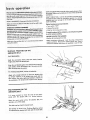
SURFACE FINISHING ON THE
ABRASIVE BELT.
FLATSURFACES
\
\
Hold the work piece firmly with both hands, keeping
fingers away from the abrasive belt.
Keep the end butted against the backstop and move the
work evenly across the abrasive belt. Use extra caution
when finishing very thin pieces.
For finishing long pieces, remove the backstop.
Apply only enough pressure to allow the abrasive belt
to remove material. If the abras=ve belt stalls and the
belt pulleys slip while applying moderate pressure to
the workpiece, the abrasive belt reouires more tension.
/
/
END FINISHING ON THE
ABRASIVE BELT,
I1 is more convient to finish the ends of long work-
pieces with the abrasive belt in a vertical position.
Move the work evenly across the abrasive belt. For
accuracy use amiter guage.
The table may be tilted for beveled work.
See Getting To Know Your Finishing Machine section
for adjusting the abrasive belt table and the work table,
2O
Page is loading ...
Page is loading ...
Page is loading ...
Page is loading ...
Page is loading ...
Page is loading ...
Page is loading ...
Page is loading ...
Page is loading ...
Page is loading ...
Page is loading ...
Page is loading ...
-
 1
1
-
 2
2
-
 3
3
-
 4
4
-
 5
5
-
 6
6
-
 7
7
-
 8
8
-
 9
9
-
 10
10
-
 11
11
-
 12
12
-
 13
13
-
 14
14
-
 15
15
-
 16
16
-
 17
17
-
 18
18
-
 19
19
-
 20
20
-
 21
21
-
 22
22
-
 23
23
-
 24
24
-
 25
25
-
 26
26
-
 27
27
-
 28
28
-
 29
29
-
 30
30
-
 31
31
-
 32
32


Craftsman 113.225900 User manual
- Category
- Power tools
- Type
- User manual
Ask a question and I''ll find the answer in the document
Finding information in a document is now easier with AI
Related papers
-
Craftsman 113225941 Owner's manual
-
-
-
-
-
-
-
-
-
Sears 113226430 User manual
Other documents
-
 Hampton Bay FG-MDL18TBL Operating instructions
-
Skil 3375-01 User manual
-
Wen 6502 User guide
-
PowerTec BD4600 Owner's manual
-
-
PowerTec BD1502 Owner's manual
-
-
-
-
Ryobi BD4601G Owner's manual
