
Manufacturer reserves the right to discontinue, or change at any time, specifications or designs without notice and without incurring obligations.
Catalog No. 04-53500007-01 Printed in U.S.A. Form 50R-5SI Pg 1 6-07 Replaces: 50R-4SI
Book 1 4
Ta b 5 a 5 a
Installation, Start-Up, and
Service Instructions
CONTENTS
Page
SAFETY CONSIDERATIONS . . . . . . . . . . . . . . . . . . .1,2
GENERAL . . . . . . . . . . . . . . . . . . . . . . . . . . . . . . . . . . . . . . . . 2
INSTALLATION . . . . . . . . . . . . . . . . . . . . . . . . . . . . . 2-26
Step 1 — Check Jobsite . . . . . . . . . . . . . . . . . . . . . . . . 2
Step 2 — Check Unit . . . . . . . . . . . . . . . . . . . . . . . . . . . 2
• STORAGE
•PROTECTION
•INSPECT UNIT
Step 3 — Unit Location. . . . . . . . . . . . . . . . . . . . . . . . . . 14
• FIELD CONVERSION OF DISCHARGE AIR
Step 4 — Mounting the Unit . . . . . . . . . . . . . . . . . . . . . 15
• HORIZONTAL UNITS
• VERTICAL UNITS
Step 5 — Duct System . . . . . . . . . . . . . . . . . . . . . . . . . . 15
• SO U ND AT TE N U AT I ON
• EXISTING DUCT SYSTEM
Step 6 — Condensate Drain . . . . . . . . . . . . . . . . . . . . . 16
• HORIZONTAL UNITS
• VERTICAL UNITS
• VENTING
Step 7 — Piping Connections . . . . . . . . . . . . . . . . . . . 16
• WATER LOOP APPLICATIONS
• GROUND-WATER APPLICATIONS
• GROUND-LOOP APPLICATIONS
Step 8 — Field Power Supply Wiring . . . . . . . . . . . . 18
• POWER CONNECTION
• SUPPLY VOLTAGE
• 208-VOLT OPERATION
Step 9 — Field Control Wiring. . . . . . . . . . . . . . . . . . . 18
• THERMOSTAT CONNECTIONS
• WATER FREEZE PROTECTION
• AIR COIL FREEZE PROTECTION
• ACCESSORY CONNECTIONS
• WATER SOLENOID VALVES
PRE-START-UP. . . . . . . . . . . . . . . . . . . . . . . . . . . . . . . 26-30
System Checkout. . . . . . . . . . . . . . . . . . . . . . . . . . . . . 26
PSC Blower Speed Selection . . . . . . . . . . . . . . . . . . 27
FIELD SELECTABLE INPUTS . . . . . . . . . . . . . . . 30-32
C Control Jumper Settings . . . . . . . . . . . . . . . . . . . . 30
C Control DIP Switches . . . . . . . . . . . . . . . . . . . . . . . 30
D Control Jumper Settings . . . . . . . . . . . . . . . . . . . . 30
D Control DIP Switches . . . . . . . . . . . . . . . . . . . . . . . 30
Units with Modulating Hot Water Reheat
(HWR) Option . . . . . . . . . . . . . . . . . . . . . . . . . . . . . . 31
D Control Accessory Relay Configurations . . . . . 32
Water Valve (Slow Opening) . . . . . . . . . . . . . . . . . . . 32
Outside Air Damper (OAD) . . . . . . . . . . . . . . . . . . . . 32
START-UP . . . . . . . . . . . . . . . . . . . . . . . . . . . . . . . . . . . . 32-36
Operating Limits . . . . . . . . . . . . . . . . . . . . . . . . . . . . . . . . 33
Scroll Compressor Rotation. . . . . . . . . . . . . . . . . . . . . 33
Unit Start-Up Cooling Mode . . . . . . . . . . . . . . . . . . . . . 33
Unit Start-Up Heating Mode . . . . . . . . . . . . . . . . . . . . . 34
Flow Regulation. . . . . . . . . . . . . . . . . . . . . . . . . . . . . . . . . 34
Page
Flushing . . . . . . . . . . . . . . . . . . . . . . . . . . . . . . . . . . . . . . . . 34
Antifreeze . . . . . . . . . . . . . . . . . . . . . . . . . . . . . . . . . . . . . . . 35
Cooling Tower/Boiler Systems . . . . . . . . . . . . . . . . . . 36
Ground Coupled, Closed Loop and Plateframe
Heat Exchanger Well Systems . . . . . . . . . . . . . . . . 36
OPERATION. . . . . . . . . . . . . . . . . . . . . . . . . . . . . . . . . . .36,37
Power Up Mode . . . . . . . . . . . . . . . . . . . . . . . . . . . . . . . . . 36
Units with Aquazone Complete C Control . . . . . . . 36
Units with Aquazone Deluxe D Control . . . . . . . . . . 36
Units with HWR Option. . . . . . . . . . . . . . . . . . . . . . . . . . 37
SYSTEM TEST . . . . . . . . . . . . . . . . . . . . . . . . . . . . . . . .37,38
Test Mode . . . . . . . . . . . . . . . . . . . . . . . . . . . . . . . . . . . . . . . 37
Retry Mode. . . . . . . . . . . . . . . . . . . . . . . . . . . . . . . . . . . . . . 37
Aquazone Deluxe D Control LED Indicators . . . . . 38
SERVICE . . . . . . . . . . . . . . . . . . . . . . . . . . . . . . . . . . . . . 38-40
Filters . . . . . . . . . . . . . . . . . . . . . . . . . . . . . . . . . . . . . . . . . . . 38
Water Coil . . . . . . . . . . . . . . . . . . . . . . . . . . . . . . . . . . . . . . . 38
Condensate Drain Pans . . . . . . . . . . . . . . . . . . . . . . . . . 38
Refrigerant System. . . . . . . . . . . . . . . . . . . . . . . . . . . . . . 38
Compressor . . . . . . . . . . . . . . . . . . . . . . . . . . . . . . . . . 39
Fan Motors. . . . . . . . . . . . . . . . . . . . . . . . . . . . . . . . . . . 39
Condensate Drain Cleaning . . . . . . . . . . . . . . . . . . . 39
Air Coil Cleaning . . . . . . . . . . . . . . . . . . . . . . . . . . . . . 39
Condenser Cleaning. . . . . . . . . . . . . . . . . . . . . . . . . . 39
Checking System Charge . . . . . . . . . . . . . . . . . . . . . 39
Refrigerant Charging . . . . . . . . . . . . . . . . . . . . . . . . . 40
Air Coil Fan Motor Removal . . . . . . . . . . . . . . . . . . . . . 40
TROUBLESHOOTING . . . . . . . . . . . . . . . . . . . . . . . . 40-42
Thermistor . . . . . . . . . . . . . . . . . . . . . . . . . . . . . . . . . . . . . . 40
Control Sensors. . . . . . . . . . . . . . . . . . . . . . . . . . . . . . . . . 40
50RHC,RVC,RHR,RHS,RVR,RVS,RDS
START-UP CHECKLIST . . . . . . . . . . . . . . . . . . CL-1, CL-2
SAFETY CONSIDERATIONS
Installation and servicing of air-conditioning equipment can
be hazardous due to system pressure and electrical compo-
nents. Only trained and qualified service personnel should
install, repair, or service air-conditioning equipment.
Untrained personnel can perform basic maintenance func-
tions of cleaning coils and filters and replacing filters. All other
operations should be performed by trained service personnel.
When working on air-conditioning equipment, observe precau-
tions in the literature, tags and labels attached to the unit, and
other safety precautions that may apply.
Improper installation, adjustment, alteration, service, mainte-
nance, or use can cause explosion, fire, electrical shock or other
conditions which may cause personal injury or property dam-
age. Consult a qualified installer, service agency, or your distrib-
utor or branch for information or assistance. The qualified in-
staller or agency must use factory-authorized kits or accessories
when modifying this product. Refer to the individual instruc-
tions packaged with the kits or accessories when installing.
IMPORTANT: Read the entire instruction manual before
starting installation.
AQUAZONE™
50RHC,RVC,RHR,RHS,
RVR,RVS,RDS006-060
Water Source Heat Pump Units

2
Follow all safety codes. Wear safety glasses and work
gloves. Use quenching cloth for brazing operations. Have fire
extinguisher available. Read these instructions thoroughly and
follow all warnings or cautions attached to the unit. Consult
local building codes and the National Electrical Code (NEC)
for special installation requirements.
Understand the signal words — DANGER, WARNING,
and CAUTION. DANGER identifies the most serious hazards
which will result in severe personal injury or death. WARN-
ING signifies hazards that could result in personal injury or
death. CAUTION is used to identify unsafe practices, which
would result in minor personal injury or product and property
damage.
Recognize safety information. This is the safety-alert
symbol ( ). When you see this symbol on the unit and in
instructions or manuals, be alert to the potential for personal
injury.
GENERAL
This Installation and Start-Up Instructions literature is for
Aquazone™ water source heat pump systems.
Water source heat pumps (WSHPs) are single-package hori-
zontally and vertically mounted units with electronic controls
designed for year-round cooling and heating. Aquazone
WSHPs are available in the following unit configurations:
• RHC standard efficiency with horizontal airflow and
right, left or back discharge
• RHR high efficiency with horizontal airflow and right,
left or back discharge
• RHS premium efficiency with horizontal airflow and
right, left or back discharge
• RVC standard efficiency with vertical airflow and top
discharge
• RVR high efficiency with vertical airflow and top
discharge
• RVS premium efficiency with vertical airflow and top
discharge
• RDS premium efficiency with vertical airflow and bot-
tom discharge (downflow)
INSTALLATION
Step 1 — Check Jobsite —
Installation, operation and
maintenance instructions are provided with each unit. Before
unit start-up, read all manuals and become familiar with the
unit and its operation. Thoroughly check out the system before
operation. Complete the inspections and instructions listed
below to prepare a unit for installation. See Tables 1-3 for unit
physical data.
HORIZONTAL UNITS (50RHC,RHR,RHS) — Horizontal
units are designed for indoor installation only. Be sure to allow
adequate space around the unit for servicing. See Fig. 1-3 for
overall unit dimensions. Refer to Fig. 4 for an illustration of a
typical horizontal installation.
VERTICAL AND DOWNFLOW UNITS (50RVC,RVR,
RVS,RDS) — Vertical units are designed for indoor installa-
tions. While vertical units are typically installed in a floor-level
closet or a small mechanical room, the unit access guidelines
for these units are very similar to those described for horizontal
units. See Fig. 5-8 for overall dimensions. Refer to Fig. 9 for an
example of a typical vertical installation. Refer to Fig. 10 for a
sample downflow installation.
Step 2 — Check Unit — Upon receipt of shipment at
the jobsite, carefully check the shipment against the bill of
lading. Make sure all units have been received. Inspect the car-
ton or crating of each unit, and inspect each unit for damage.
Ensure the shipping company makes proper notation of any
shortages or damage on all copies of the freight bill. Concealed
damage not discovered during unloading must be reported to
the shipping company within 15 days of receipt of shipment.
NOTE: It is the responsibility of the purchaser to file all
necessary claims with the shipping company.
1. Verify unit is correct model for entering water tempera-
ture of job.
2. Be sure that the location chosen for unit installation pro-
vides ambient temperatures maintained above freezing.
Well water applications are especially susceptible to
freezing.
3. Be sure the installation location is isolated from sleeping
areas, private offices and other acoustically sensitive
spaces.
NOTE: A sound control accessory package may be used
to help eliminate sound in sensitive spaces.
4. Check local codes to be sure a secondary drain pan is not
required under the unit.
5. Be sure unit is mounted at a height sufficient to provide
an adequate slope of the condensate lines. If an appropri-
ate slope cannot be achieved, a field-supplied condensate
pump may be required.
6. Provide sufficient space for duct connection.
7. Provide adequate clearance for filter replacement and
drain pan cleaning. Do not allow piping, conduit, etc. to
block filter access.
8. Provide sufficient access to allow maintenance and
servicing of the fan and fan motor, compressor and coils.
Removal of the entire unit from the closet should not be
necessary.
9. Provide an unobstructed path to the unit within the closet
or mechanical room. Space should be sufficient to allow
removal of unit if necessary.
10. Provide ready access to water valves and fittings, and
screwdriver access to unit side panels, discharge collar,
and all electrical connections.
11. Where access to side panels is limited, pre-removal of the
control box side mounting screws may be necessary for
future servicing.
Electrical shock can cause personal injury or death. Before
installing or servicing system, always turn off main power
to system. There may be more than one disconnect switch.
Turn off accessory heater power if applicable.
IMPORTANT: The installation of water source heat pump
units and all associated components, parts, and accessories
which make up the installation shall be in accordance with
the regulations of ALL authorities having jurisdiction and
MUST conform to all applicable codes. It is the responsi-
bility of the installing contractor to determine and comply
with ALL applicable codes and regulations.
To avoid equipment damage, do not use these units as a
source of heating or cooling during the construction
process. The mechanical components and filters used in
these units quickly become clogged with construction
dirt and debris which may cause system damage.

3
STORAGE — If the equipment is not needed immediately at
the jobsite, it should be left in its shipping carton and stored in a
clean, dry area of the building or in a warehouse. Units must be
stored in an upright position at all times. If carton stacking is
necessary, stack units a maximum of 3 high. Do not remove
any equipment from its shipping package until it is needed for
installation.
PROTECTION — Once the units are properly positioned on
the jobsite, cover them with either a shipping carton, vinyl film,
or an equivalent protective covering. Cap open ends of pipes
stored on the jobsite. This precaution is especially important in
areas where painting, plastering, or spraying of fireproof mate-
rial, etc. is not yet complete. Foreign material that accumulates
within the units can prevent proper start-up and necessitate
costly clean-up operations.
Before installing any of the system components, be sure to
examine each pipe, fitting, and valve, and remove any dirt or
foreign material found in or on these components.
INSPECT UNIT — To prepare the unit for installation, com-
plete the procedures listed below:
1. Compare the electrical data on the unit nameplate with
ordering and shipping information to verify that the
correct unit has been shipped.
2. Verify that the unit is the correct model for the entering
water temperature of the job.
3. Do not remove the packaging until the unit is ready for
installation.
4. Verify that the refrigerant tubing is free of kinks or dents,
and that it does not touch other unit components.
5. Inspect all electrical connections. Be sure connections are
clean and tight at the terminals.
6. Loosen compressor bolts until the compressor rides freely
on springs. Remove shipping restraints.
7. Remove the four
1
/
4
in. shipping bolts from compressor
support plate (two bolts on each side) to maximize vibra-
tion and sound alternation.
8. Remove any blower support cardboard from inlet of the
blower.
9. Locate and verify any accessory kit located in compressor
section.
10. Remove any access panel screws that may be difficult to
remove once unit is installed.
DO NOT store or install units in corrosive environments or
in locations subject to temperature or humidity extremes
(e.g., attics, garages, rooftops, etc.). Corrosive conditions
and high temperature or humidity can significantly reduce
performance, reliability, and service life. Always move
units in an upright position. Tilting units on their sides may
cause equipment damage.
Failure to remove shipping brackets from spring-mounted
compressors will cause excessive noise and could cause
component failure due to added vibration.

4
Table 1 — Physical Data — Aquazone™ 50RHC,RVC006-060 Units
LEGEND
*Size 006 available in 50RHC unit only.
†Size 041 available in 50RVC unit only.
NOTES:
1. All units have grommet compressor mountings, and
1
/
2
and
3
/
4
-in.
electrical knockouts.
2. All sizes available as high-static units.
UNIT 50RHC,RVC 006* 009 012 018 024 030
COMPRESSOR (1 each) Rotary
Reciprocating
FACTORY REFRIGERANT CHARGE R-22
VERTICAL (oz)
—1414263837
FACTORY REFRIGERANT CHARGE R-22
HORIZONTAL (oz)
14 14 14 25 38 37
PSC FAN MOTOR AND BLOWER
Fan Motor Type/Speeds PSC/3 PSC/3 PSC/3 PSC/3 PSC/3 PSC/3
Fan Motor Std/High Static (Hp)
1
/
25
/—
1
/
10
/—
1
/
10
/—
1
/
8
/
1
/
6
1
/
4
/
3
/
4
3
/
4
/
3
/
4
Blower Wheel Size (D x W) (in.) Std/High Static 5 x 5/— 5 x 5/— 6 x 5/— 8 x 7/8 x 7 9 x 7/9 x 7 9 x 7/10 x 8
WATER CONNECTION SIZE (FPT)
1
/
2
1
/
2
1
/
2
1
/
2
3
/
4
3
/
4
VERTICAL
Air Coil
Dimensions (H x W) (in.) — 10 x 15 10 x 15 20 x 17.25 20 x 17.25 20 x 17.25
Total Face Area (ft
2
) — 1.04 1.04 2.4 2.4 2.4
Tube Size (in.) —
3
/
8
3
/
8
3
/
8
3
/
8
3
/
8
Fin Spacing (FPI) —1212121212
Number of Rows —23233
Filter Standard — 1-in. Throwaway — 10 x 18 10 x 18 1 — 20 x 20 1 — 20 x 20 1 — 20 x 20
Weight (lb)
Operating — 105 114 181 189 197
Packaged — 115 124 186 194 202
HORIZONTAL
Air Coil
Dimensions (H x W) (in.) 10 x 15 10 x 15 10 x 15 16 x 22 16 x 22 16 x 22
Total Face Area (ft
2
) 1.04 1.04 1.04 2.44 2.44 2.44
Tube Size (in.)
3
/
8
3
/
8
3
/
8
3
/
8
3
/
8
3
/
8
Fin Spacing (FPI) 12 12 12 12 12 12
Number of Rows 223233
Filter Standard — 1-in. Throwaway 10 x 18 10 x 18 10 x 18 1 — 16 x 25 1 — 16 x 25 1 — 16 x 25
Weight (lb)
Operating 103 105 114 181 189 197
Packaged 113 115 124 186 194 202
UNIT 50RHC,RVC 036 041† 042 048 060
COMPRESSOR (1 each) Reciprocating Scroll
FACTORY REFRIGERANT CHARGE R-22
VERTICAL (oz)
42 50 51 66 74
FACTORY REFRIGERANT CHARGE R-22
HORIZONTAL (oz)
41 50 51 66 74
PSC FAN MOTOR AND BLOWER
Fan Motor Type/Speeds PSC/3 PSC/3 PSC/3 PSC/3 PSC/3
Fan Motor Std/High Static (Hp)
1
/
2
/
3
/
4
3
/
4
/—
3
/
4
/
3
/
4
3
/
4
/1 1/1
Blower Wheel Size (D x W) (in.) Std/High Static 9 x 8/10 x 8 9 x 8/— 9 x 8/10 x 8 10 x 10/12 x 10 11 x 10/11 x 10
WATER CONNECTION SIZE (FPT)
3
/
4
3
/
4
3
/
4
11
VERTICAL
Air Coil
Dimensions (H x W) (in.) 24 x 21.25 1 — 20 x 17.25 24 x 21.25 24 x 28.25 20 x 28.25
Total Face Area (ft
2
) 3.62 2.4 3.62 4.71 4.71
Tube Size (in.)
3
/
8
3
/
8
3
/
8
3
/
8
3
/
8
Fin Spacing (FPI) 14 11 12 12 12
Number of Rows 2433 3
Filter Standard — 1-in. Throwaway 1 — 24 x 24 1 — 20 x 20 1 — 24 x 24
1 — 14 x 24
1 — 18 x 24
1 — 14 x 24
1 — 18 x 24
Weight (lb)
Operating 203 207 218 263 278
Packaged 209 212 224 270 285
HORIZONTAL
Air Coil
Dimensions (H x W) (in.) 20 x 25 — 20 x 25 20 x 35 20 x 35
Total Face Area (ft
2
) 3.47 — 3.47 4.86 4.86
Tube Size (in.)
3
/
8
—
3
/
8
3
/
8
3
/
8
Fin Spacing (FPI) 14 — 12 12 12
Number of Rows 2—3 3 3
Filter Standard — 1-in. Throwaway
1 — 20 x 28
2 — 20 x 14
—
1 — 20 x 28
2 — 20 x 14
1 — 20 x 24
1 — 20 x 14
1 — 20 x 24
1 — 20 x 14
Weight (lb)
Operating 203 — 218 263 278
Packaged 209 — 224 270 285
FPI — Fins per Inch
PSC — Permanent Split Capacitor

5
Table 2 — Physical Data — Aquazone™ 50RHR,RVR006-060 Units
LEGEND
*Size 006 available in 50RHR unit only.
NOTES:
1. All units have spring compressor mountings, TXV (thermostatic
expansion valve) expansion devices, and
1
/
2
and
3
/
4
-in. electrical
knockouts.
2. Size 048 available as high-static unit.
Table 3 — Physical Data — Aquazone 50RHS,RVS,RDS015-070 Units
LEGEND NOTES:
1. All units have spring compressor mountings, TXV (thermostatic
expansion valve) expansion devices, and
1
/
2
and
3
/
4
-in. electrical
knockouts.
2. Size 030 and 036 available as high-static units.
UNIT 50RHR,RVR 006* 009 012 015 019 024 030 036 042 048 060
COMPRESSOR (1 each) Rotary Reciprocating Scroll
FACTORY CHARGE R-22 (oz) 12 15 15 30 30 30 41 44 46 54 80
PSC FAN MOTOR AND BLOWER
Fan Motor Type/Speeds PSC/3 PSC/3 PSC/3 PSC/3 PSC/3 PSC/3 PSC/3 PSC/3 PSC/3 PSC/3 PSC/3
Fan Motor (Hp)
1
/
25
1
/
10
1
/
10
1
/
6
1
/
5
1
/
3
1
/
2
3
/
4
3
/
4
3
/
4
1
Blower Wheel Size (D x W) (in.) 5 x 5 5 x 5 6 x 5 9 x 7 9 x 7 9 x 7 9 x 7 10 x 10 10 x 10 10 x 10 11 x 10
WATER CONNECTION SIZE (FPT)
1
/
2
1
/
2
1
/
2
3
/
4
3
/
4
3
/
4
3
/
4
3
/
4
11 1
VERTICAL
Air Coil
Dimensions (H x W) (in.) — 10 x 16 16 x 16 20 x 20 28 x 20 28 x 25
Total Face Area (ft
2
) — 1.1 1.8 2.8 3.9 4.9
Tube Size (in.)
—
3
/
8
3
/
8
3
/
8
3
/
8
3
/
8
Fin Spacing (FPI) —1212121210
Number of Rows —33334
Filter Standard — 1-in. Throwaway — 10 x 20 16 x 20 20 x 24 28 x 24 28 x 30
Weight (lb)
Operating — 112 121 147 169 193 219 229 257 267 323
Packaged — 122 131 157 179 203 231 241 269 279 338
HORIZONTAL
Air Coil
Dimensions (H x W) (in.) 10 x 16 16 x 16 18 x 22 18 x 31 20 x 35
Total Face Area (ft
2
) 1.1 1.8 2.8 3.9 4.9
Tube Size (in.)
3
/
8
3
/
8
3
/
8
3
/
8
3
/
8
Fin Spacing (FPI) 12 12 12 12 10
Number of Rows 223 3 3 3 4
Filter Standard — 1-in. Throwaway 1 — 10 x 20 1 — 16 x 20 1 — 18 x 24 2 — 18 x 18
1 — 12 x 20
1 — 25 x 20
Weight (lb)
Operating 110 112 121 147 169 193 219 229 257 267 323
Packaged 120 122 131 157 179 203 231 241 269 279 338
FPI — Fins per Inch
PSC — Permanent Split Capacitor
UNIT 50RHS,RVS,RDS 015 018 024 030 036 042 048 060 070
COMPRESSOR (1 each) Rotary Scroll
FACTORY CHARGE R-22 (oz) 44 44 48 48 60 74 74 102 104
PSC FAN MOTOR AND BLOWER
Fan Motor Type/Speeds PSC/3 PSC/3 PSC/3 PSC/3 PSC/3 PSC/3 PSC/3 PSC/3 PSC/3
Fan Motor (Hp)
1
/
6
1
/
6
1
/
5
1
/
3
1
/
2
1
/
2
3
/
4
3
/
4
1
Blower Wheel Size (D x W) (in.) 9 x 7 9 x 7 9 x 7 9 x 7 9 x 7 10 x 10 10 x 10 11 x 10 11 x 10
WATER CONNECTION SIZE (FPT) (in.)
3
/
4
3
/
4
3
/
4
3
/
4
3
/
4
1111
HWG CONNECTION SIZE (FPT) (in.)
1
/
2
1
/
2
1
/
2
1
/
2
1
/
2
1
/
2
1
/
2
1
/
2
1
/
2
VERTICAL/DOWNFLOW
Air Coil
Dimensions (H x W) (in.) 20 x 20 24 x 20 28 x 20 28 x 25 32 x 25 36 x 25
Total Face Area (ft
2
) 2.8 3.3 3.9 4.9 5.6 6.3
Tube Size (in.)
3
/
8
3
/
8
3
/
8
3
/
8
3
/
8
3
/
8
Fin Spacing (FPI) 12 12 12 10 10 10
Number of Rows 3 33444
Filter Standard — 1-in. Throwaway 1 — 20 x 24 1 — 24 x 24
2 — 14 x
24
2 — 14 x 30
2 — 10 x
30
1 — 12 x
30
3 — 12 x
30
Weight (lb)
Operating 174 184 250 252 266 323 327 416 443
Packaged 184 194 260 262 276 333 337 426 453
HORIZONTAL
Air Coil
Dimensions (H x W) (in.) 18 x 22 18 x 27 18 x 31 20 x 35 20 x 40 20 x 45
Total Face Area (ft
2
) 2.8 3.4 3.9 4.9 5.6 6.3
Tube Size (in.)
3
/
8
3
/
8
3
/
8
3
/
8
3
/
8
3
/
8
Fin Spacing (FPI) 12 12 12 10 10 10
Number of Rows 3 33444
Filter Standard — 1-in. Throwaway 1 — 18 x 24 2 — 18 x 18
2 — 18 x
18
2 — 12 x
20
1 — 20 x
25
1 — 18 x
20
1 — 24 x
20
2 — 24 x
20
Weight (lb)
Operating 179 189 250 252 266 323 327 416 443
Packaged 189 199 260 262 276 333 337 426 453
FPI — Fins per Inch
HWG — Hot Water Generator
PSC — Permanent Split Capacitor

6
Fig. 1 — 50RHC Dimensional Data
NOTES:
1. Condensate is
3
/
4
-in. FPT copper.
2. Horizontal unit shipped with filter bracket only. This bracket should be removed for return duct connection.
3. Hanger kit is factory installed.
50RHC
UNITS
OVERALL CABINET
WATER CONNECTIONS ELECTRICAL KNOCKOUTS (in.)
DISCHARGE CONNECTION
Duct Flange Installed (±0.10 in.)
RETURN CONNECTION
Using Air Coil Opening
1 — In 2 — Out
H
1
/
2
conduit
J
1
/
2
conduit
K
3
/
4
conduit
A
Width
B
Depth
C
Height
D E F G Therm Ext Pump
Power
Supply
L
M
Supply
Height
N
Supply
Depth
OP
Q
Return
Depth
R
Return
Height
ST
006-012
in. 19.1 34.1 11.0 9.6 0.8 1.8 0.8 8.1 5.1 2.1 0.8 8.9 6.7 5.2 1.3 16.1 9.8 1.1 0.6
cm 48.5 86.6 27.9 24.4 2.0 4.4 2.0 20.6 13.0 5.4 1.9 22.7 17.0 13.3 3.3 41.0 25.0 2.7 1.5
018-030
in. 20.1 43.1 17.1 15.3 2.4 1.9 2.1 12.1 9.1 6.1 2.6 13.3 9.9 4.1 1.3 23.0 15.0 1.1 1.0
cm 51.1 109.5 43.4 38.9 6.1 4.9 5.3 30.8 23.2 15.6 6.6 33.8 25.1 10.5 3.3 58.4 38.1 2.8 2.5
036-042
in. 20.1 47.1 21.1 18.8 2.2 4.7 1.2 16.1 13.1 10.1 2.5 16.1 11.0 3.0 2.5 25.9 19.0 1.1 1.0
cm 51.1 119.6 53.6 47.6 5.5 11.9 3.0 41.0 33.3 25.7 6.3 40.9 27.9 7.7 6.4 65.8 48.3 2.8 2.5
048
in. 24.1 54.1 21.1 19.4 5.9 4.3 2.3 16.1 13.1 10.1 3.7 16.1 13.7 4.1 1.3 35.9 19.0 1.1 1.0
cm 61.2 137.4 53.6 49.2 14.9 11.0 5.8 41.0 33.3 25.7 9.5 41.0 34.8 10.3 3.2 91.2 48.3 2.8 2.5
060
in. 24.1 54.1 21.1 19.4 5.9 4.3 2.3 16.1 13.1 10.1 1.7 18.1 13.7 4.1 1.3 35.9 19.0 1.1 1.0
cm 61.2 137.4 53.6 49.2 14.9 11.0 5.8 41.0 33.3 25.7 4.4 46.0 34.8 10.3 3.2 91.2 48.3 2.8 2.5
AIRFLOW CONFIGURATION
Code Return Discharge
S Left Right
E Left Back
Z Right Left
B Right Back
LEGEND
ASP — Alternate Service Panel
BSP — Blower Service Panel
CAP — Control Access Panel
CSP — Compressor Service Panel
a50-8155

7
Fig. 2 — 50RHR Dimensional Data
Front
K
M
Blower
Outlet
M
L
Right Return
Front
Left
Discharge
3
CSP
Back
Discharge
Condensate
3/4
“
FTP
3.25
F
Front-View
BSP
Air Coil
C
S
R
B
ASP
Q
P
Front
K
M
Blower
Outlet
J
L
Front
BSP
LEFT RETURN RIGHT RETURN
Air Coil
CSP
Front
1.1
C
S
Q
PR
B
Unit Hanger Detail
X
Y
Front
Z
Model X Y Z
006-024 43.1 24.375 20.375
030-036 53.1 24.375 20.375
042-048 62.1 24.375 20.375
060 71.1 27.375 23.375
B Configuration - Right Return Back Discharge
ASP
CSP
Front
Left Return
F
3.25
CSP
Condensate
3/4
“
FPT
ASP
3
‘
Service
Access
3
Right
Discharge
Back
Discharge
E Configuration - Left Return Back Discharge
Water
Connection
Water
Connection
2
‘
Service
Access
S Configuration - Left Return Right Discharge -
Air Coil Opening
3‘
SERVICE
ACCESS
Right
View
Left
View
S Configuration - Left Return Right Discharge -
Air Coil Opening
Z Configuration - Right Return Left Discharge -
Air Coil Opening
Left
View
Right
View
Z Configuration - Right Return Left Discharge -
Air Coil Opening
N
BSP
O
M
C
A
Blower
Outlet
Air Coil Side
L
1/2“
Knockout
Low Voltage
1/2
“ Knockout
Power Supply
3/4
“ Knockout
A
1.6 [40.6mm]
I
H
G
D
E
1
2
M
N
C
L
O
A
BSP
Air Coil Side
Blower
Outlet
ASP
CAP
3op?œŸ•‘ “ ’
²±¢p³µ¶·¸¹º»¼½¾¿ÀÁÂ?‘’“”•…†‡denµ´ÇÆÅÄ´
AIRFLOW CONFIGURATION
Code Return Discharge
S Left Right
E Left Back
Z Right Left
B Right Back
LEGEND
ASP — Alternate Service Panel
BSP — Blower Service Panel
CAP — Control Access Panel
CSP — Compressor Service Panel
NOTES:
1. Condensate is
3
/
4
-in. FPT copper.
2. Horizontal unit shipped with filter bracket only. This bracket should be removed for return duct connection.
3. Hanger kit is factory installed. Isolation grommets are provided.
4. Right and left orientation is determined by looking at water connection side.
50RHR
UNITS
OVERALL
CABINET
WATER
CONNECTIONS
ELECTRICAL KNOCKOUTS (in.)
DISCHARGE CONNECTION
Duct Flange Installed (±0.10 in.)
RETURN CONNECTION
Using Return Air Opening
12 3
Loop
Water
FPT
(in.)
G
1
/
2
conduit
H
1
/
2
conduit
I
3
/
4
conduit
A
Width
B
Depth
C
Height
D
In
E
Out
F
Cond-
ensate
Therm
Ext
Pump
Power
Supply
JK
L
Supply
Height
M
Supply
Depth
NO
P
Return
Depth
Q
Return
Height
RS
006-012
in. 22.4 43.1 11.3 2.4 5.4 0.6
1
/
2
3.5 5.5 8.2 5.8 4.0 5.8 8.0 5.8 1.5 17.1 9.3 2.2 1.0
cm 56.8 109.5 28.7 6.1 13.7 1.5 8.9 14.0 20.8 14.7 10.2 14.7 20.3 14.7 3.8 43.4 23.6 5.6 2.5
015-024
in. 22.4 43.1 17.3 2.4 4.9 0.6
3
/
4
3.5 7.5 10.2 5.0 5.6 10.4 9.3 5.0 1.5 17.1 15.3 2.2 1.0
cm 56.8 109.5 43.9 6.1 12.4 1.5 8.9 19.1 25.9 12.7 14.2 26.4 23.6 12.7 3.8 43.4 38.9 5.6 2.5
030
in. 22.4 53.2 19.3 2.4 5.4 0.6
3
/
4
5.7 9.7 12.2 5.0 6.8 10.4 9.3 5.0 2.1 23.1 17.3 2.2 1.0
cm 56.8 135.1 49.0 6.1 13.7 1.5 14.5 24.6 31.0 12.7 17.3 26.4 23.6 12.7 5.3 58.7 43.9 5.6 2.5
036
in. 22.4 53.2 19.3 2.4 5.4 0.6
3
/
4
5.7 9.7 12.2 2.9 3.8 13.5 13.1 2.9 1.9 23.1 17.3 2.2 1.0
cm 56.8 135.1 49.0 6.1 13.7 1.5 14.5 24.6 31.0 7.4 9.7 34.3 33.3 7.4 4.8 58.7 43.9 5.6 2.5
042-048
in. 22.4 62.2 19.3 2.4 5.4 0.6
1
5.7 9.7 12.2 2.9 3.8 13.5 13.1 2.9 1.9 32.1 17.3 2.2 1.0
cm 56.8 158.0 49.0 6.1 13.7 1.5 14.5 24.6 31.0 7.4 9.7 34.3 33.3 7.4 4.8 81.5 43.9 5.6 2.5
060
in. 25.4 71.2 21.3 2.4 5.4 0.6
1
8.1 11.7 14.2 5.8 5.0 13.6 13.3 5.8 2.9 36.1 19.3 2.2 1.0
cm 64.5 180.8 54.1 6.1 13.7 1.5 20.6 29.7 36.1 14.7 12.7 34.5 33.8 14.7 7.4 91.7 49.0 5.6 2.5
a50-8156

8
Fig. 3 — 50RHS Dimensional Data
NOTES:
1. Condensate is
3
/
4
-in. FPT copper.
2. Horizontal unit shipped with filter bracket only. This bracket should be removed for return duct connection.
3. Hanger kit is factory installed. Isolation grommets are provided.
4. Right and left orientation is determined by looking at water connection side.
50RHS
UNITS
OVERALL CABINET
WATER CONNECTIONS ELECTRICAL KNOCKOUTS (in.)
DISCHARGE CONNECTION
Duct Flange Installed (±0.10 in.)
RETURN CONNECTION
Using Air Coil Opening
12 3
Loop
Water
FPT
(in.)
HWG
FPT
(in.)
G
1
/
2
conduit
H
1
/
2
conduit
I
3
/
4
conduit
A
Width
B
Depth
C
Height
D
In
E
Out
F
Cond-
ensate
Therm Ext Pump
Power
Supply
JK
L
Supply
Height
M
Supply
Depth
NO
P
Return
Depth
Q
Return
Height
RS
015-018
in. 22.4 53.2 19.3 2.4 5.4 0.6
3
/
4
1
/
2
5.7 9.7 12.2 5.0 6.8 10.4 9.3 5.0 2.1 23.1 17.3 2.2 1.0
cm 56.8 135.1 49.0 6.1 13.7 1.5 14.5 24.6 31.0 12.7 17.3 26.4 23.6 12.7 5.3 58.7 43.9 5.6 2.5
024-030
in. 22.4 62.2 19.3 2.4 5.4 0.6
3
/
4
1
/
2
5.7 9.7 12.2 5.0 6.8 10.4 9.3 5.0 2.1 28.1 17.3 2.2 1.0
cm 56.8 158.0 49.0 6.1 13.7 1.5 14.5 24.6 31.0 12.7 17.3 26.4 23.6 12.7 5.3 71.4 43.9 5.6 2.5
036
in. 22.4 62.2 19.3 2.4 5.4 0.6
3
/
4
1
/
2
5.7 9.7 12.2 5.0 6.8 10.4 9.3 5.0 2.1 32.1 17.3 2.2 1.0
cm 56.8 158.0 49.0 6.1 13.7 1.5 14.5 24.6 31.0 12.7 17.3 26.4 23.6 12.7 5.3 81.5 43.9 5.6 2.5
042-048
in. 25.4 71.2 21.3 2.4 5.4 0.6
1
1
/
2
8.1 11.7 14.2 5.8 5.0 13.6 13.3 5.8 2.9 36.1 19.3 2.2 1.0
cm 64.5 180.8 54.1 6.1 13.7 1.5 20.6 29.7 36.1 14.7 12.7 34.5 33.8 14.7 7.4 91.7 49.0 5.6 2.5
060
in. 25.4 76.2 21.3 2.4 5.4 0.6
1
1
/
2
8.1 11.7 14.2 5.8 5.0 13.6 13.3 5.8 2.9 41.1 19.3 2.2 1.0
cm 64.5 193.5 54.1 6.1 13.7 1.5 20.6 29.7 36.1 14.7 12.7 34.5 33.8 14.7 7.4 104.4 49.0 5.6 2.5
070
in. 25.4 81.2 21.3 2.4 5.4 0.6
1
1
/
2
8.1 11.7 14.2 5.8 5.0 13.6 13.3 5.8 2.9 46.1 19.3 2.2 1.0
cm 64.5 206.2 54.1 6.1 13.7 1.5 20.6 29.7 36.1 14.7 12.7 34.5 33.8 14.7 7.4 117.1 49.0 5.6 2.5
AIRFLOW CONFIGURATION
Code Return Discharge
S Left Right
E Left Back
Z Right Left
B Right Back
LEGEND
ASP — Alternate Service Panel
BSP — Blower Service Panel
CAP — Control Access Panel
CSP — Compressor Service Panel
a50-8157

9
Fig. 4 — Typical Installation — 50RHC,RHR,RHS Units
UNIT HANGER ISOLATION DETAIL

10
Fig. 5 — 50RVC Dimensional Data
NOTES:
1. Condensate is
3
/
4
-in. (19.1 mm) FPT.
2. Filter bracket extending from unit 2.5-in. (6.4 cm). This bracket should be removed when connecting return duct.
3. Discharge flange field installed.
50RVC
UNITS
OVERALL CABINET
WATER CONNECTIONS ELECTRICAL KNOCKOUTS (in.)
DISCHARGE CONNECTION
Duct Flange Installed (±0.10 in.)
RETURN CONNECTION
Using Air Coil Opening
12 3
Water
FPT
Size
J
1
/
2
conduit
K
1
/
2
conduit
L
3
/
4
conduit
A
Width
B
Depth
C
Height
DE FG H I
Therm
Ext.
Pump
Power
Supply
MN
O
Supply
Width
P
Supply
Depth
QR
S
Return
Depth
T
Return
Height
U
In Out Condensate
009-012
in. 19.1 19.1 22.0 1.4 2.8 9.4 2.8 6.1 2.3 1/2 2.9 5.9 8.9 8.9 5.1 9.0 9.0 5.5 2.1 16.2 9.9 0.7
cm 48.5 48.5 55.9 3.6 7.1 24.0 7.1 15.6 5.9 1.3 7.3 14.9 22.5 22.7 12.9 22.9 22.9 14.0 5.3 41.1 25.1 1.9
018-030
in. 21.5 21.5 39.0 1.8 3.8 15.2 3.6 8.1 2.3
3
/
4
4.1 7.1 10.1 6.4 3.8 14.0 14.0 5.3 2.3 18.3 20.2 0.7
cm 54.6 54.6 99.1 4.5 9.7 38.6 9.1 20.6 5.8 1.9 10.5 18.1 25.7 16.1 9.5 35.6 35.6 13.6 5.8 46.5 51.3 1.9
036 & 042
in. 21.5 26.0 44.0 2.0 3.7 16.2 2.6 10.4 2.3
3
/
4
4.1 7.1 10.1 6.4 3.8 14.0 14.0 5.1 2.3 22.8 24.2 0.7
cm 54.6 66.0 111.8 5.1 9.4 41.1 6.6 28.4 5.8 1.9 10.5 18.1 25.7 16.1 9.5 35.6 35.6 13.1 5.8 57.9 61.4 1.9
041
in. 21.5 21.5 39.0 1.7 3.6 16.4 2.6 8.1 2.3
3
/
4
4.1 7.1 10.1 6.4 3.8 14.0 14.0 5.3 2.3 18.3 20.2 0.7
cm 54.6 54.6 99.1 4.4 9.1 41.7 6.6 20.6 5.8 1.9 10.5 18.1 25.7 16.1 9.5 35.6 35.6 13.6 5.8 46.5 51.3 1.9
048-060
in. 24.0 32.5 46.0 1.8 5.9 16.7 2.3 10.1 2.3 1 4.1 7.1 10.1 6.9 7.3 16.0 18.0 5.1 2.3 29.3 24.2 0.7
cm 6.10 82.6 116.8 4.5 14.9 42.4 5.8 25.7 5.8 2.5 10.5 18.1 25.7 17.4 18.4 40.6 45.7 13.1 5.8 74.4 61.4 1.9
AIRFLOW CONFIGURATION
Code Return Discharge
L Left Top
R Right Top
LEGEND
ASP — Alternate Service Panel
BSP — Blower Service Panel
CAP — Control Access Panel
CSP — Compressor Service Panel
a50-8158

11
Fig. 6 — 50RVR Dimensional Data
NOTES:
1. Condensate is
3
/
4
-in. FPT and is switchable from side to front.
2. Vertical unit shipped with filter bracket only extending from unit 2.5 inches. This bracket should be removed when connecting return duct.
3. Discharge flange field installed.
4. Right and left orientation is determined by looking at water connection side.
50RVR
UNITS
OVERALL CABINET
WATER CONNECTIONS ELECTRICAL KNOCKOUTS (in.)
DISCHARGE CONNECTION
Duct Flange Installed (±0.10 in.)
RETURN CONNECTION
Using Air Coil Opening
12 3
Loop
Water
FPT
(in.)
G
1
/
2
conduit
H
1
/
2
conduit
I
3
/
4
conduit
A
Width
B
Depth
C
Height
D
In
E
Out
F
Cond-
ensate
Therm Ext Pump
Power
Supply
JK
L
Supply
Height
M
Supply
Depth
NO
P
Return
Depth
Q
Return
Height
R
009-012
in. 22.4 21.6 22.6 2.6 5.4 7.8
1
/
2
3.5 5.5 8.2 10.6 6.8 5.8 8.0 6.0 2.2 17.1 9.3 1.0
cm 56.8 54.9 57.4 6.6 13.7 19.8 8.9 14.0 20.8 26.9 17.3 14.7 20.3 15.2 5.6 43.4 23.6 2.5
015-024
in. 22.4 21.6 34.6 2.4 4.8 8.5
3
/
4
3.5 7.5 10.2 7.2 3.8 14.0 14.0 4.3 2.2 17.1 15.3 1.0
cm 56.8 54.9 87.9 6.1 12.2 21.6 8.9 19.1 25.9 18.3 9.7 35.6 35.6 10.9 5.6 43.4 38.9 2.5
030
in. 22.4 25.6 40.6 2.4 5.4 9.7
3
/
4
5.7 9.7 12.2 7.2 5.8 14.0 14.0 4.3 2.2 21.1 19.2 1.0
cm 56.8 65.1 103.1 6.1 13.7 24.6 14.5 24.6 31.0 18.3 14.7 35.6 35.6 10.9 5.6 53.6 48.8 2.5
036
in. 22.4 25.6 40.6 2.4 5.4 9.7
3
/
4
5.7 9.7 12.2 7.2 5.8 14.0 14.0 4.3 2.2 21.1 19.2 1.0
cm 56.8 65.1 103.1 6.1 13.7 24.6 14.5 24.6 31.0 18.3 14.7 35.6 35.6 10.9 5.6 53.6 48.8 2.5
042-048
in. 22.4 25.6 48.6 2.4 5.4 9.7
1
5.7 9.7 12.2 7.2 5.8 14.0 14.0 4.3 2.2 21.1 27.2 1.0
cm 56.8 65.1 123.4 6.1 13.7 24.6 14.5 24.6 31.0 18.3 14.7 35.6 35.6 10.9 5.6 53.6 69.1 2.5
060
in. 25.4 30.6 50.6 2.4 5.4 10.7
1
8.1 11.7 14.2 6.2 6.3 18.0 18.0 5.1 2.2 26.1 27.2 1.0
cm 64.5 77.8 128.5 6.1 13.7 27.2 20.6 29.7 36.1 15.7 16.0 45.7 45.7 13.0 5.6 66.3 69.1 2.5
AIRFLOW CONFIGURATION
Code Return Discharge
L Left Top
R Right Top
Access Panels
L Configuration - Top View-Left Return
R Configuration - Top View-Right Return
R
O
P
Isometric
View
L Configuration - Left Return Left View
- Air Coil Opening
Q
C
Condensate
3/4
“
FPT
Front View
H
1.000
G
F
E
D
I
Air Coil
Field Installed
Discharge Flange
(Shipped loose in
blower section)
Front
Back
R
O
P
Q
C
Back
Front
BSP
CAP
Standard Filter Bracket
ASP
ASP
Air Coil
Front
M
K
L
N
Front
3’ Service
Access
Left Return
(right
Opposite)
K
B
M
A
L
J
3’ Service
Access
1
2
3
CSP
CAP
CSP
CSP
Air Coil
Air Coil Side
Air Coil Side
ASP
R Configuration - Right Return Right View
- Air Coil Opening
Front
Water Connection
1/2
“
Knockout
Power for
Condensate Pump
Low Voltage
1/2“ LV Knockout
Power Supply
3/4“ HV Knockout
Water
Connections
LEGEND
ASP — Alternate Service Panel
BSP — Blower Service Panel
CAP — Control Access Panel
CSP — Compressor Service Panel
LEFT RETURN
RIGHT RETURN
a50-8159

12
Fig. 7 — 50RVS Dimensional Data
NOTES:
1. Condensate is
3
/
4
-in. FPT and is switchable from side to front.
2. Vertical unit shipped with filter bracket only extending from unit 2.5 inches. This bracket should be removed when connecting return duct.
3. Discharge flange field installed.
4. Right and left orientation is determined by looking at water connection side.
50RVS
UNITS
OVERALL CABINET
WATER CONNECTIONS ELECTRICAL KNOCKOUTS (in.)
DISCHARGE CONNECTION
Duct Flange Installed (±0.10 in.)
RETURN CONNECTION
Using Air Coil Opening
12 3
Loop
Water
FPT
(in.)
HWG
FPT
(in.)
G
1
/
2
conduit
H
1
/
2
conduit
I
3
/
4
conduit
A
Width
B
Depth
C
Height
D
In
E
Out
F
Cond-
ensate
Therm Ext Pump
Power
Supply
JK
L
Supply
Height
M
Supply
Depth
NO
P
Return
Depth
Q
Return
Height
R
015-018
in. 22.4 25.6 40.6 2.4 5.4 9.7
3
/
4
1
/
2
5.7 9.7 12.2 7.2 5.8 14.0 14.0 4.3 2.2 21.1 19.2 1.0
cm 56.8 65.1 103.1 6.1 13.7 24.6 14.5 24.6 31.0 18.3 14.7 35.6 35.6 10.9 5.6 53.6 48.8 2.5
024-030
in. 22.4 25.6 44.6 2.4 5.4 9.7
3
/
4
1
/
2
5.7 9.7 12.2 7.2 5.8 14.0 14.0 4.3 2.2 21.1 23.2 1.0
cm 56.8 65.1 113.3 6.1 13.7 24.6 14.5 24.6 31.0 18.3 14.7 35.6 35.6 10.9 5.6 53.6 58.9 2.5
036
in. 22.4 25.6 48.6 2.4 5.4 9.7
3
/
4
1
/
2
5.7 9.7 12.2 7.2 5.8 14.0 14.0 4.3 2.2 21.1 27.2 1.0
cm 56.8 65.1 123.4 6.1 13.7 24.6 14.5 24.6 31.0 18.3 14.7 35.6 35.6 10.9 5.6 53.6 69.1 2.5
042-048
in. 25.4 30.6 50.6 2.4 5.4 10.7
1
1
/
2
8.1 11.7 14.2 6.2 6.3 18.0 18.0 5.1 2.2 26.1 27.2 1.0
cm 64.5 77.8 128.5 6.1 13.7 27.2 20.6 29.7 36.1 15.7 16.0 45.7 45.7 13.0 5.6 66.3 69.1 2.5
060
in. 25.4 30.6 54.6 2.4 5.4 10.7
1
1
/
2
8.1 11.7 14.2 6.2 6.3 18.0 18.0 5.1 2.2 26.1 31.2 1.0
cm 64.5 77.8 138.7 6.1 13.7 27.2 20.6 29.7 36.1 15.7 16.0 45.7 45.7 13.0 5.6 66.3 79.2 2.5
070
in. 25.4 30.6 58.6 2.4 5.4 10.7
1
1
/
2
8.1 11.7 14.2 6.2 6.3 18.0 18.0 5.1 2.2 26.1 35.2 1.0
cm 64.5 77.8 148.8 6.1 13.7 27.2 20.6 29.7 36.1 15.7 16.0 45.7 45.7 13.0 5.6 66.3 89.4 2.5
AIRFLOW CONFIGURATION
Code Return Discharge
L Left Top
R Right Top
Access Panels
L Configuration - Top View-Left Return
R Configuration - Top View-Right Return
R
O
P
Isometric
View
L Configuration - Left Return Left View
- Air Coil Opening
Q
C
Condensate
3/4
“
FPT
Front View
H
1.000
G
F
E
D
I
Air Coil
Field Installed
Discharge Flange
(Shipped loose in
blower section)
Front
Back
R
O
P
Q
C
Back
Front
BSP
CAP
Standard Filter Bracket
ASP
ASP
Air Coil
Front
M
K
L
N
Front
3’ Service
Access
Left Return
(right
Opposite)
K
B
M
A
L
J
3’ Service
Access
1
2
3
CSP
CAP
CSP
CSP
Air Coil
Air Coil Side
Air Coil Side
ASP
R Configuration - Right Return Right View
- Air Coil Opening
Front
Water Connection
1/2
“
Knockout
Power for
Condensate Pump
Low Voltage
1/2“ LV Knockout
Power Supply
3/4“ HV Knockout
Water
Connections
RIGHT RETURN
LEFT RETURN
LEGEND
ASP — Alternate Service Panel
BSP — Blower Service Panel
CAP — Control Access Panel
CSP — Compressor Service Panel
a50-8169

13
Fig. 8 — 50RDS Dimensional Data
LEGEND
HWG — Hot Water Generator
NOTES:
1. Condensate is
3
/
4
-in. PVC FPT and is switchable from side to front.
2. Vertical unit shipped with filter bracket only extending from unit 2.5 inch. This bracket should be removed when connecting return duct.
50RDS
UNITS
OVERALL CABINET
WATER CONNECTIONS (in.) ELECTRICAL KNOCKOUTS (in.)
DISCHARGE CONNECTION
Outlet Opening Only
RETURN CONNECTION
Using Return Air Opening
12 3 4 5
Loop
Water
FPT
(in.)
HWG
FPT
(in.)
J
1
/
2
conduit
K
1
/
2
conduit
L
3
/
4
conduit
A
Width
B
Depth
C
Height
D
In
E
Out
F
HWG
In
G
HWG
Out
H
Cond-
ensate
Therm
Ext
Pump
Power
Supply
MN
O
Supply
Width
P
Supply
Depth
QR
S
Return
Depth
T
Return
Height
U
015-018
in.
22.4 25.6 44.6 16.9 13.9 5.4 2.4 3.5
3/4 1/2
13.6 9.7 7.2 6.1 8.2 10.4 9.3 11.0 2.2 21.1 20.2 20.4
cm 56.8 65.1 113.3 42.9 35.3 13.7 6.1 8.9 34.5 24.6 18.3 15.4 20.8 26.4 23.5 27.9 5.6 53.6 51.3 51.8
024-030
in.
22.4 25.6 48.6 16.9 13.9 5.4 2.4 3.5
3/4 1/2
13.6 9.7 7.2 6.1 8.2 10.4 9.3 11.0 2.2 21.1 24.2 20.4
cm 56.8 65.1 123.4 42.9 35.3 13.7 6.1 8.9 34.5 24.6 18.3 15.4 20.8 26.4 23.5 27.9 5.6 53.6 61.5 51.8
036
in.
22.4 25.6 52.6 16.9 13.9 5.4 2.4 3.5
3/4 1/2
13.6 9.7 7.2 6.1 8.2 10.4 9.3 11.0 2.2 21.1 28.2 20.4
cm 56.8 65.1 133.6 42.9 35.3 13.7 6.1 8.9 34.5 24.6 18.3 15.4 20.8 26.4 23.5 27.9 5.6 53.6 71.6 51.8
042-048
in.
25.4 30.6 54.6 18.9 15.9 5.4 2.4 3.5
11/2
13.1 9.7 7.2 7.2 8.7 13.6 13.3 10.5 2.2 26.1 28.2 22.4
cm 64.5 77.8 138.7 48.0 40.4 13.7 6.1 8.9 33.3 24.6 18.3 18.3 22.1 34.4 33.7 26.7 5.6 66.3 71.6 56.9
060
in.
25.4 30.6 58.6 18.9 15.9 5.4 2.4 3.5
11/2
13.1 9.7 7.2 7.2 8.7 13.6 13.3 10.5 2.2 26.1 32.2 22.4
cm 64.5 77.8 148.8 48.0 40.4 13.7 6.1 8.9 33.3 24.6 18.3 18.3 22.1 34.4 33.7 26.7 5.6 66.3 81.8 56.9
070
in.
25.4 30.6 62.6 18.9 15.9 5.4 2.4 3.5
11/2
13.1 9.7 7.2 7.2 8.7 13.6 13.3 10.5 2.2 26.1 36.2 22.4
cm 64.5 77.8 159.0 48.0 40.4 13.7 6.1 8.9 33.3 24.6 18.3 18.3 22.1 34.4 33.7 26.7 5.6 66.3 91.9 56.9
3’ Service
Access
Air Coil Side
G
F
D
K
J
L
4
3
2
1
5
CAP
T
U
R
S
Air Coil
CSP
Front
Back
Front-View
BSP
Left Return -
Air Coil Opening
(Left Side View)
Condensate
3/4
”
FPT
Left Return
Condensate
3/4
”
FPT
Right Return
5
1.1
1.6
1.6
T
U
S
Air Coil
Front
Back
Right Return-
Air Coil Opening
(Right Side View)
R
ASP
Front
P
O
N
M
Blower
Opening
H
C
B
A
Front
P
O
N
Q
Blower
Opening
B
A
Right Return/Bottom Discharge
Floor Foot Print
(Top View)
Left Return/Bottom Discharge
Floor Foot Print
(Top View)
CSP
Isometric View
Condensate 3/4”
FPT
ASP
CSP
CAP
BSP
Standard Filter Bracket
3’ Service
Access Left Rtn
(right opposite)
ASP
E
Air Coil Side
Power Supply
3/4
”
HV Knockout
1/2
”
Knockout
Low Voltage
1/2
”
LV Knockout
LEGEND
ASP — Alternate Service Panel
BSP — Blower Service Panel
CAP — Control Access Panel
CSP — Compressor Service Panel
a50-
6743ef.
eps

14
Step 3 — Unit Location — The following guidelines
should be considered when choosing a location for a WSHP:
• Units are for indoor use only.
• Locate in areas where ambient temperatures are between
40 F and 100 F and relative humidity is no greater than
75%.
• Provide sufficient space for water, electrical and duct
connections.
• Locate unit in an area that allows easy access and
removal of filter and access panels.
• Allow enough space for service personnel to perform
maintenance.
• Return air must be able to freely enter the space if unit
needs to be installed in a confined area such as a closet.
NOTE: Correct placement of the horizontal unit can play an
important part in minimizing sound problems. Since duct-
work is normally applied to these units, the unit can be
placed so that the principal sound emission is outside the oc-
cupied space in sound-critical applications. A fire damper
may be required by the local code if a fire wall is penetrated.
FIELD CONVERSION OF DISCHARGE AIR — The dis-
charge air of the 50RHC,RHR,RHS horizontal units can be
converted between side and back discharge in the field. The
conversion process is the same for right and left return configu-
rations. See Fig. 11 and 12.
NOTE: It is not possible to convert return air between left or
right return models in the field due to refrigerant piping
changes.
Preparation
— The unit should be on the ground in a well lit
area for conversion. Hung units should be taken down to
ground level before converting.
Side to Back Discharge Conversion
1. Remove screws to free the top and discharge panels. See
Fig. 11.
2. Remove the access panel and set aside.
3. Lift the discharge panel from side of unit and rotate it to
back using care not to damage blower wiring.
4. Check blower wire routing and connections for undo
tension or contact with sheet metal edges. Re-route if
necessary.
5. Check refrigerant tubing for contact with other compo-
nents. Adjust if necessary.
6. Reinstall top panel using screws set aside in Step 1.
NOTE: Location for some screws at bottom of discharge panel
may have to be changed.
7. Manually spin fan wheel to check for obstructions.
Adjust for any obstruction found.
8. Replace access panel.
Back to Side Discharge Conversion
— Follow instructions
above for Side to Back Discharge Conversion, noting the
panels would be reversed.
Return
Air
Power
Thermostat
Wiring
Compressor
Access Panel
Balancing Valve
(field installed
and calibrated
accessory)
Field-supplied
stainless steel
braid hose
with integral
“ J” swivel
Low Pressure
Drop Water
Control Valve
(optional)
(field-installed
accessory)
Ball Valve with optional
integral P/T plug
(typical for supply and
return piping)
Water
Out
Water
In
Building
Loop
Supply Air
Flexible
Connection
NOTE: Ball valve with integral pressure temperature plug recommended.
Fig. 9 — Typical Vertical Installation —
50RVC,RVR,RVS Units
Return
Air
Power
Thermostat
Wiring
Compressor
Access Panel
Balancing Valve
(field-installed
and calibrated
accessory)
Field-supplied
stainless steel
braid hose
with integral
“ J” swivel
Low Pressure
Drop Water
Control Valve (optional)
(field-installed
accessory)
Ball Valve with optional
integral P/T plug
(typical for supply and
return piping)
Water
Out
Water
In
Building
Loop
Supply Air
Flexible
Connection
Flexible
Connection
NOTE: Ball valve with integral pressure temperature plug recommended.
Fig. 10 — Typical Downflow Installation —
50RDS Units
Return Air
Remove Screws
Return Air
Rotate
Move to Side
Side Discharge
Return Air
Discharge Air
Drain
Back Discharge
Replace Screws
Water
Connection End
Water
Connection End
Water
Connection End
Fig. 11 — Conversion Left Return,
Side Discharge to Back Discharge

15
Step 4 — Mounting the Unit
HORIZONTAL UNITS (50RHC,RHR,RHS) — Horizontal units
should be mounted using the factory-installed hangers. Proper
attachment of hanging rods to building structure is critical for
safety. See Fig. 4 and 13. Rod attachments must be able to sup-
port the weight of the unit. See Tables 1-3 for unit operating
weights.
VERTICAL UNITS (50RVC,RVR,RVS,RDS) — Vertical and
downflow units are available in left or right return air configu-
rations. See Fig. 6-8. Mount the unit (except 50RDS) on a
vibration absorption pad slightly larger than the entire base to
minimize vibration transmission. It is not necessary to mount
the unit on the floor. See Fig. 14.
NOTE: Some codes require the use of a secondary drain pan
under vertical units. Check local codes for more information.
Step 5 — Duct System — Size the duct system to han-
dle the design airflow quietly.
NOTE: Depending on the unit, the fan wheel may have a ship-
ping support installed at the factory. This must be removed
before operating unit.
SOUND ATTENUATION — To eliminate the transfer of
vibration to the duct system, a flexible connector is recom-
mended for both discharge and return air duct connections on
metal duct systems. The supply and return plenums should in-
clude internal duct liner of fiberglass or be made of duct board
construction to maximize sound attenuation of the blower.
Installing the WSHP unit to uninsulated ductwork in an uncon-
ditioned space is not recommended since it will sweat and
adversely affect the unit’s performance.
To reduce air noise, at least one 90-degree elbow could be
included in the supply and return air ducts, provided system
performance is not adversely impacted. The blower speed can
also be changed in the field to reduce air noise or excessive air-
flow, provided system performance is not adversely impacted.
EXISTING DUCT SYSTEM — If the unit is connected to
existing ductwork, consider the following:
• Verify that the existing ducts have the proper capacity to
handle the unit airflow. If the ductwork is too small,
install larger ductwork.
• Check existing ductwork for leaks and repair as
necessary.
NOTE: Local codes may require ventilation air to enter the
space for proper indoor air quality. Hard-duct ventilation may
be required for the ventilating air supply. If hard ducted venti-
lation is not required, be sure that a proper air path is provided
for ventilation air to unit to meet ventilation requirement of the
space.
Water
Connection End
Supply
Duct
Return Air
Water
Connection End
Drain
Return Air
Discharge Air
Side Discharge
Back Discharge
Fig. 12 — Conversion Right Return,
Side Discharge to Back Discharge
Compressor
Section
Air Handler
Section
B
A
C
E
D
D
Fig. 13 — Horizontal Hanger Bracket
(Factory Installed)
50RHC UNITS
DIMENSIONS (in.)
ABC
006-012 16.9 34.1 21.1
018-030 18 43.1 22.2
036,042 18 47.1 22.2
048,060 22 54.1 26.2
50RHR UNITS
DIMENSIONS (in.)
ABCDE
006-024 22.375 43.1 24.375 43.1 20.375
030,036 22.375 52.1 24.375 52.1 20.375
042,048 22.375 61.1 24.375 61.1 20.375
060 25.375 71.1 27.375 71.1 23.375
50RHS UNITS
DIMENSIONS (in.)
ABCDE
015,018 22.375 51 24.375 53 20.375
024-036 22.375 61 24.375 63 20.375
042,048 25.375 70 27.375 72 20.375
060 25.375 75 27.375 77 23.375
070 25.375 80 27.375 82 23.375
Vibration
Absorption
Pad
Fig. 14 — 50RVC,RVR,RVS Units Mounted With
Vibration Absorption Pad

16
Step 6 — Condensate Drain
HORIZONTAL UNITS (50RHC,RHR,RHS) — Slope the
unit toward the drain at a
1
/
4
in. drop at drain end. See Fig. 15.
If it is not possible to meet the required pitch, install a conden-
sate pump at the unit to pump condensate to building drain.
Horizontal units are not internally trapped, therefore an ex-
ternal trap is necessary. Install each unit with its own individual
trap and means to flush or blowout the condensate drain line.
Do not install units with a common trap or vent. For typical
condensate connections see Fig. 16.
NOTE: Never use a pipe size smaller than the connection.
VERTICAL UNITS (50RVC,RVR,RVS) — Each unit uses a
condensate hose inside all cabinets as a trapping loop, therefore
an external trap is not necessary. See Fig. 17.
Each unit must be installed with its own individual vent and
means to flush or blowout the condensate drain line. Do not in-
stall units with a common trap or vent.
VENTING — Install a vent in the condensate line of any
application that may allow dirt or air to collect in the line. Con-
sider the following:
• Always install a vent where an application requires a
long horizontal run.
• Always install a vent where large units are working
against higher external static pressure and to allow
proper drainage for multiple units connected to the same
condensate main.
• Be sure to support the line where anticipated sagging from
the condensate or when “double trapping” may occur.
• If condensate pump is present on unit, be sure drain con-
nections have a check valve to prevent back flow of con-
densate into other units.
Step 7 — Piping Connections — Depending on the
application, there are 3 types of WSHP piping systems to
choose from: water loop, ground-water and ground loop. Refer
to Piping Section of Carrier System Design Manual for addi-
tional information.
All WSHP units use low temperature soldered female pipe
thread fittings for water connections to prevent annealing and
out-of-round leak problems which are typically associated with
high temperature brazed connections. Refer to Tables 1-3 for
connection sizes. When making piping connections, consider
the following:
• Use a backup wrench when making screw connections to
unit to prevent internal damage to piping.
• Insulation may be required on piping to avoid condensa-
tion in the case where fluid in loop piping operates at
temperatures below dew point of adjacent air.
• Piping systems that contain steel pipes or fittings may
be subject to galvanic corrosion. Dielectric fittings may
be used to isolate the steel parts of the system to avoid
galvanic corrosion.
WATER LOOP APPLICATIONS — Water loop applications
usually include a number of units plumbed to a common pip-
ing system. Maintenance to any of these units can introduce air
into the piping system. Therefore, air elimination equipment
comprises a major portion of the mechanical room plumbing.
The flow rate is usually set between 2.25 and 3 gpm per ton
of cooling capacity. For proper maintenance and servicing,
pressure-temperature (P/T) ports are necessary for temperature
and flow verification.
In addition to complying with any applicable codes, consid-
er the following for system piping:
• Piping systems using water temperatures below 50 F
require
1
/
2
-in. closed cell insulation on all piping surfaces
to eliminate condensation.
• Avoid all plastic to metal threaded fittings due to the
potential to leak. Use a flange fitted substitute.
• Teflon tape thread sealant is recommended to minimize
internal fouling of the heat exchanger.
• Use backup wrench. Do not overtighten connections.
• Route piping to avoid service access areas to unit.
• Flush the piping system prior to operation to remove dirt
and foreign materials from the system.
GROUND-WATER APPLICATIONS (Not Applicable to
50RHC,RVC Units) — Typical ground-water piping is
shown in Fig. 18. In addition to complying with any appli-
cable codes, consider the following for system piping:
• Install shut-off valves for servicing.
• Install pressure-temperature plugs to measure flow and
temperature.
• Connect boiler drains and other valves using a “T” con-
nector to allow acid flushing for the heat exchanger.
• Do not overtighten connections.
• Route piping to avoid service access areas to unit.
• Use PVC SCH80 or copper piping material.
NOTE: PVC SCH40 should not be used due to system high
pressure and temperature extremes.
Fig. 15 — Horizontal Unit Pitch
NOTE: Trap should be deep enough to offset maximum unit static
difference. A 4-in. trap is recommended.
Fig. 16 — Trap Condensate Drain
Alternate
Condensate
Location
Vent
1/4” per foot
slope to drain
3/4” Copper FPT/PVC
Water
Connections
1/2”
1/2”
3/4” PVC
NOTE: Unit does not need to be sloped toward drain.
Fig. 17 — Vertical Condensate Connection
1/4” Pitch for
Drainage
Drain Connection
Pitch Toward
Drain

17
Water Supply and Quantity
— Check water supply. Water
supply should be plentiful and of good quality. See Table 4 for
water quality guidelines.
In all applications, the quality of the water circulated
through the heat exchanger must fall within the ranges listed in
the Water Quality Guidelines table. Consult a local water treat-
ment firm, independent testing facility, or local water authority
for specific recommendations to maintain water quality within
the published limits.
GROUND-LOOP APPLICATIONS (Not Applicable to
50RHC,RVC Units) — Temperatures between 25 to 110 F
and a cooling capacity of 2.25 to 3 gpm of flow per ton is rec-
ommended. In addition to complying with any applicable
codes, consider the following for system piping:
• Limit piping materials to only polyethylene fusion in the
buried sections of the loop.
• Do not use galvanized or steel fittings at any time due to
corrosion.
• Avoid all plastic to metal threaded fittings due to the
potential to leak. Use a flange fitted substitute.
• Do not overtighten connections.
• Route piping to avoid service access areas to unit.
• Use pressure-temperature (P/T) plugs to measure flow of
pressure drop.
Table 4 — Water Quality Guidelines
*If the concentration of these corrosives exceeds the maximum allowable level, then the potential for serious corrosion
problems exists.
†Sulfides in the water quickly oxidize when exposed to air, requiring that no agitation occur as the sample is taken.
Unless tested immediately at the site, the sample will require stabilization with a few drops of one Molar zinc acetate
solution, allowing accurate sulfide determination up to 24 hours after sampling. A low pH and high alkalinity cause sys-
tem problems, even when both values are within ranges shown. The term pH refers to the acidity, basicity, or neutrality
of the water supply. Below 7.0, the water is considered to be acidic. Above 7.0, water is considered to be basic. Neutral
water contains a pH of 7.0.
NOTE: To convert ppm to grains per gallon, divide by 17. Hardness in mg/l is equivalent to ppm.
IMPORTANT: Failure to comply with the above required
water quality and quantity limitations and the closed-
system application design requirements may cause damage
to the tube-in-tube heat exchanger that is not the responsi-
bility of the manufacturer.
CONDITION ACCEPTABLE LEVEL
pH 7 to 9 range for copper. Cupronickel may be used in the 5 to 9 range.
Total Hardness Calcium and magnesium carbonate should not exceed 20 grains per gallon (350 ppm).
Iron Oxides Less than 1 ppm.
Iron Bacteria No level allowable.
Corrosion* Max Allowable Level Coaxial Metal
Ammonia, Ammonium Hydroxide 0.5 ppm Cu
Ammonium Chloride, Ammonium Nitrate 0.5 ppm Cu
Ammonium Sulfate 0.5 ppm Cu
Chlorine/Chlorides 0.5 ppm CuNi
Hydrogen Sulfide† None Allowable —
Brackish Use Cupronickel heat exchanger when concentrations of calcium or sodium chloride are greater
than 125 ppm are present. (Seawater is approximately 25,000 ppm.)
Pressure-
Temperature
Plugs
Boiler
Drains
Strainer – Field-Installed Accessory
(16 to 20 mesh recommended for
filter sediment)
Shut-Off
Valve
Water
Control
Valve
Flow
Regulator
Pressure
Tank
Water Out
Water In
From Pump
Fig. 18 — Typical Ground-Water Piping Installation

18
Step 8 — Field Power Supply Wiring
All field installed wiring, including the electrical ground,
MUST comply with the National Electrical Code (NEC) as
well as applicable local codes. In addition, all field wiring must
conform to the Class II temperature limitations described in the
NEC.
Refer to unit wiring diagrams Fig. 19-22 for a schematic of
the field connections, which must be made by the installing (or
electrical) contractor. Refer to Tables 5-7 for fuse sizes.
Consult the unit wiring diagram located on the inside of the
compressor access panel to ensure proper electrical hookup.
The installing (or electrical) contractor must make the field
connections when using field-supplied disconnect.
Operating voltage must be the same voltage and phase as
shown in Electrical Data shown in Tables 5-7.
Make all final electrical connections with a length of flexi-
ble conduit to minimize vibration and sound transmission to
the building.
POWER CONNECTION — Make line voltage connection
by connecting the incoming line voltage wires to the L side
of the CC terminal as shown in Fig. 23. See Tables 5-7 for
correct wire and maximum overcurrent protection sizing.
SUPPLY VOLTAGE — Operating voltage to unit must be
within voltage range indicated on unit nameplate.
On 3-phase units, voltages under load between phases must
be balanced within 2%. Use the following formula to deter-
mine the percentage voltage imbalance:
% Voltage Imbalance
Example: Supply voltage is 460-3-60.
AB = 452 volts
BC = 464 volts
AC = 455 volts
Determine maximum deviation from average voltage:
(AB) 457 – 452 = 5 v
(BC) 464 – 457 = 7 v
(AC) 457 – 455 = 2 v
Maximum deviation is 7 v.
Determine percent voltage imbalance.
This amount of phase imbalance is satisfactory as it is
below the maximum allowable 2%.
Operation on improper line voltage or excessive phase
imbalance constitutes abuse and may cause damage to electri-
cal components.
NOTE: If more than 2% voltage imbalance is present, contact
your local electric utility.
208-VOLT OPERATION — All 208-230 volt units are factory
wired for 208 volts. The transformers may be switched to
230-volt operation by switching the red (208 volt) wire with
the orange (230 volt) wire at the L1 terminal.
Step 9 — Field Control Wiring
THERMOSTAT CONNECTIONS — The thermostat should
be wired directly to the Aquazone™ control board. See
Fig. 19-22, and 24.
WATER FREEZE PROTECTION — The Aquazone control
allows the field selection of source fluid freeze protection
points through jumpers. The factory setting of jumper JW3
(FP1) is set for water at 30 F. In earth loop applications, jumper
JW3 should be clipped to change the setting to 10 F when
using antifreeze in colder earth loop applications. See Fig. 25.
AIR COIL FREEZE PROTECTION — The air coil freeze
protection jumper JW2 (FP2) is factory set for 30 F and should
not need adjusting.
ACCESSORY CONNECTIONS — Terminal A on the control
is provided to control accessory devices such as water valves,
electronic air cleaners, humidifiers, etc. This signal operates
with the compressor terminal. See Fig. 26. Refer to the specific
unit wiring schematic for details.
NOTE: The A terminal should only be used with 24 volt
signals — not line voltage signals.
WATER SOLENOID VALVES — Water solenoid valves may
be used on primary secondary pump and ground water installa-
tions. A typical well water control valve wiring, which can
limit waste water in a lockout condition is shown in Fig. 26. A
slow closing valve may be required to prevent water hammer.
When using a slow closing valve, consider special wiring con-
ditions. The valve takes approximately 60 seconds to open
(very little water will flow before 45 seconds) and it activates
the compressor only after the valve is completely opened by
closing its end switch. When wired as shown, the valve will
have the following operating characteristics:
1. Remain open during a lockout
2. Draw approximately 25 to 35 VA through the “Y” signal
of the thermostat.
To avoid possible injury or death due to electrical shock,
open the power supply disconnect switch and secure it in
an open position during installation.
Use only copper conductors for field-installed electrical
wiring. Unit terminals are not designed to accept other
types of conductors. Failure to follow this safety precaution
could lead to equipment damage.
= 100 x
max voltage deviation from average voltage
average voltage
Average Voltage =
452 + 464 + 455
3
=
1371
3
= 457
% Voltage Imbalance = 100 x
7
457
= 1.53%
IMPORTANT: Connecting a water solenoid valve can
overheat the anticipators of electromechanical thermo-
stats. Only use relay based electronic thermostats.

19
*Optional wiring.
AL — Alarm Relay Contacts
BM — Blower Motor
BMC — Blower Motor Capacitor
BR — Blower Relay
CB — Circuit Breaker
CC — Compressor Contactor
CO — Sensor, Condensate Overflow
COMPR — Compressor
FP1 — Sensor, Water Coil Freeze Protection
FP2 — Sensor, Air Coil Freeze Protection
HP — High-Pressure Switch
HWTS — High (Leaving) Water Temperature
Switch
JW1 — Jumper, Alarm
NOTES:
1. Compressor and blower motor thermally protected internally.
2. All wiring to the unit must comply with NEC and local codes.
3. Transformer is wired to 265 v (BRN) lead for 265/1/60 units, or
208 v (RED) lead for 208/1/60. For 230/1/60 switch RED and
ORG leads at L1 and insulate RED lead. Transformer is energy
limiting or may have circuit breaker.
4. FP1 thermistor provides freeze protection for water. When using
antifreeze solutions, cut JW3 jumper.
5. Typical Aquazone thermostat wiring shown. Refer to thermostat
installation instructions for wiring to the unit. Thermostat wiring
must be Class 1 and voltage rating equal to or greater than unit
supply voltage.
Fig. 19 — Typical Aquazone™ Complete C Control Wiring
LEGEND
LOC — Loss of Charge Pressure Switch
MV — Motorized Valve
NEC — National Electrical Code
P1 — Field Wiring Terminal Block
PM — Performance Monitor
RV — Reversing Valve Coil
TRANS — Transformer
TXV — Thermostatic Expansion Valve
Field Line Voltage Wiring
Field Low Voltage Wiring
Printed Circuit Trace
Optional Wiring
Relay/Contactor Coil
Condensate Pan
Solenoid Coil
Temperature Switch
Thermistor
Ground
Wire Nut
6. 24-v alarm signal shown. For dry alarm contact, cut JW1 jumper
and dry contact will be available between AL1 and AL2.
7. Transformer secondary ground via control board standoffs and
screws to control box. (Ground available from top two standoffs
as shown.)
8. For high or low speed remove BLU wire from BR ‘NO’
and replace with BLK or RED wire respectively. Tape off unused
terminal.
9. Both DIP switches need to be in the ON position.
a50-8160

20
*Optional wiring.
AL — Alarm Relay Contacts
BM — Blower Motor
BMC — Blower Motor Capacitor
BR — Blower Relay
CB — Circuit Breaker
CC — Compressor Contactor
CO — Sensor, Condensate Overflow
COMPR — Compressor
FP1 — Sensor, Water Coil Freeze Protection
FP2 — Sensor, Air Coil Freeze Protection
HP — High-Pressure Switch
JW1 — Jumper, Alarm
LOC — Loss of Charge Pressure Switch
Fig. 20 — Typical Aquazone™ Deluxe D Control Wiring
LEGEND
MV — Motorized Valve
NEC — National Electrical Code
P1 — Field Wiring Terminal Block
RVS — Reversing Valve Solenoid
TRANS — Transformer
TXV — Thermostatic Expansion Valve
Field Line Voltage Wiring
Field Low Voltage Wiring
Printed Circuit Trace
Relay/Contactor Coil
Condensate Pan
Solenoid Coil
Thermistor
Ground
Wire Nut
NOTES:
1. Compressor and blower motor thermally protected internally.
2. All wiring to the unit must comply with NEC and local codes.
3. Transformer is wired to 208 v (RED) lead for 208/3/60. For 230/3/60
switch RED and ORG leads at L1 and insulate RED lead.
4. FP1 thermistor provides freeze protection for water. When using anti-
freeze solutions, cut JW3 jumper.
5. Typical Aquazone thermostat wiring shown. Refer to thermostat installa-
tion instructions for wiring to the unit. Thermostat wiring must be Class 1
and voltage rating equal to or greater than unit supply voltage.
6. 24-v alarm signal shown. For dry alarm contact, cut AL2 dry
jumper and dry contact will be available between AL1 and
AL2.
7. Transformer secondary ground via control board standoffs
and screws to control box. (Ground available from top two
standoffs as shown.)
8. Blower motor is factory wired for medium and high speeds.
For any other combination of speeds, attach the lower speed
wire to fan speed relay N.O. wire.
a50-8161
Page is loading ...
Page is loading ...
Page is loading ...
Page is loading ...
Page is loading ...
Page is loading ...
Page is loading ...
Page is loading ...
Page is loading ...
Page is loading ...
Page is loading ...
Page is loading ...
Page is loading ...
Page is loading ...
Page is loading ...
Page is loading ...
Page is loading ...
Page is loading ...
Page is loading ...
Page is loading ...
Page is loading ...
Page is loading ...
Page is loading ...
Page is loading ...
-
 1
1
-
 2
2
-
 3
3
-
 4
4
-
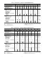 5
5
-
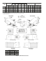 6
6
-
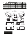 7
7
-
 8
8
-
 9
9
-
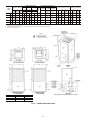 10
10
-
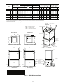 11
11
-
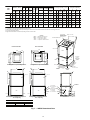 12
12
-
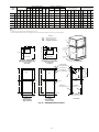 13
13
-
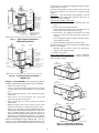 14
14
-
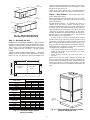 15
15
-
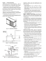 16
16
-
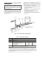 17
17
-
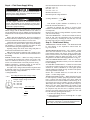 18
18
-
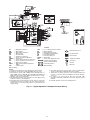 19
19
-
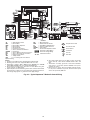 20
20
-
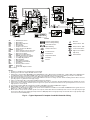 21
21
-
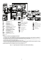 22
22
-
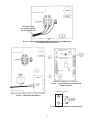 23
23
-
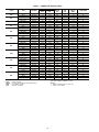 24
24
-
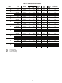 25
25
-
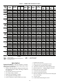 26
26
-
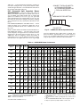 27
27
-
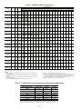 28
28
-
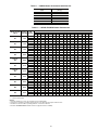 29
29
-
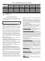 30
30
-
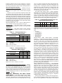 31
31
-
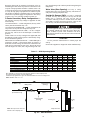 32
32
-
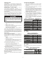 33
33
-
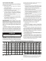 34
34
-
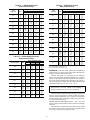 35
35
-
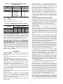 36
36
-
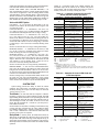 37
37
-
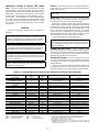 38
38
-
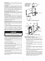 39
39
-
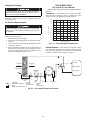 40
40
-
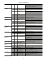 41
41
-
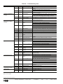 42
42
-
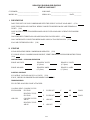 43
43
-
 44
44


Ask a question and I''ll find the answer in the document
Finding information in a document is now easier with AI
Related papers
-
Carrier 50RHE006-060 User manual
-
-
-
-
-
-
-
-
-
Other documents
-
MyBinding Best-Rite Tackboard Display Rail Assembly Instruction
-
-
-
 Edbak STD01C-B Datasheet
-
Philips SJB1142/17 User manual
-
 Heat Controller HP048 Installation, Operation & Maintenance Manual
-
A.O. Smith Conventional System Piping Technical Documents
-
ClimateMaster Horizontal/Vertical WSHP Install Manual
-
Greenheck 913836 Remote Condensing Unit Operating instructions
-
Watts 960GD-15-17,960GS-15-17 Installation guide

