Page is loading ...

caSECRS Quick Ref. rev D.
Dome Light Delay / Theater Dimming
When the Dome Light Delay is set to “Program Custom Time” in feature
programming (this is the default setting) the system can be programed to delay
arming after the lock button is pressed for vehicles with a dome light delay or theater
dimming feature. Once programed the system will ‘learn’ the timing of the dome light
delay (60 second max) and add 2 seconds before arming.
1. Closealldoorswithignitiono.
2. Using the transmitter press LOCK, UNLOCK, LOCK ,UNLOCK, LOCK ,
UNLOCK, LOCK. The LED will light solid to indicate the system has
entered DOME DELAY LEARN MODE.
3. Immediately OPEN then CLOSE the door WITHOUT disarming the
system. The system will then monitor the door trigger wire. Once the
domelightturnso,thesystemwillthenadd2secondsandthenexit
the learning mode.
4. TheLEDwillbegintoashindicatingthesystemhasexitedthe
learning mode and is now armed.
Note: To program a custom delay time Feature Bank 2, Feature 16, “Dome Light
Delay: Preset Time or Programmable, must be set to “OFF/Program Custom Time”.
Defaulting the Dome Light Delay: Turn the ignition ON then OFF 3 times then
press and hold the valet button for 5 seconds, the system will chirp 1 time indicating
the learned delay time has been cleared.
PROFESSIONAL
SERIES
Security and Remote Start
Installation Quick Reference
Guide
caSECRS
2019 Voxx Electronics Corporation. All rights reserved.
Adjusting the Shock Sensor
1. Increase sensitivity by turning the adjustment dial clockwise.
2. Decrease sensitivity by turning the adjustment dial counter clockwise.
Tach Programming
The remote start will not operate unless the tach is programmed or a tachless option
is turned ON. The default method set for Tach Mode in the feature programming
banksforconrmingthattheengineisrunningis“Tach”.Thismethodmonitorsthe
PURPLE/WHITE tach input wire. If an attempt is made to start the vehicle via the
remotestartwithoutrstprogrammingtach,theunitwillashtheparkinglights7
times indicating tach has not been learned and stored.
The Remote Start unit will learn the tach rate of most vehicle’s single coil, multiple
coil packs, or single injector. There are 2 methods for learning the vehicle’s tach rate,
to learn tach follow one of the methods below:
Standard:
1. Turn the ignition key to the ON position.
2. Press and release the valet/override button 3 times.
3. Immediately turn the ignition key OFF.
4. Press and hold the valet/override button, then start the vehicle using
the key.
5. When the unit senses the tach signal, the parking lights will begin to
ash.
6. Allow the vehicle to settle to a normal idle speed.
7. Releasethevalet/programpush-buttonswitch.Theparkinglightswillturn
on for 2 seconds and 1 long chip will indicate that the learned tach signal
is stored, and the unit has exited tach learn mode.
Without valet/override button using the Factory Remote w/Flashlogic Interface
or CarLink Device:
1. Start the vehicle’s engine leaving the ignition key in the On/Run position.
2. Press and hold the brake pedal.
3. Lock the system using the either the Factory Remote/Flashlogic Interface
or CarLink device. The system must see the lock input from either of
these two methods.
4. When the unit senses the tach signal, the parking lights will begin to
ash.
6. Allow the vehicle to settle to a normal idle speed.
7. Releasethebrakepedal.Theparkinglightswillturnonfor2secondsand
1 long chip will indicate that the tach signal has been stored, and that the
unit has exited tach learn mode.
NOTE: If the unit fails to learn tach rate due to an improper tach connection or a
poortachsource,theparkinglightswillnotash.Tocorrectthissituation,locateand
connect the PURPLE/WHITE wire to the proper tach signal, and then repeat the tach
learn routine.
Smart Tachless Mode
Smart Tachless Mode is available only if a tach signal has never been learned to the
system and when activated will automatically change the Tach Mode feature in option
programming to Tachless without the need to enter the feature programming mode.
1. Activatetheremotestart.Theparkinglightsshouldbeginashing7
times indicating no tach signal has been learned.
2. Withinthe7ashtimeperiod,pressandholdthe button.
3. The system will chirp 1 time indicating the system is now in tachless
mode.
RED
BATTERY 12V ( + )
BLACK
GROUND WHEN ARMED ( - )
BLUE FULL TRIGGER ( - )
GREEN WARN AWAY TRIGGER ( - )
SHOCK SENSOR & HARNESS
Replacement Part
#4700023
ORANGE 86 - ARMED OUTPUT ( - )
RED 85 - IGNITION ( + )
BLACK 87A - STARTER OUTPUT - MOTOR SIDE
WHITE / BLACK 30 - STARTER INPUT - KEY SIDE
OPEN 87 - OPEN
STARTER INTERUPT RELAY & HARNESS
86
85
30
87
87a
Replacement Part
#1024405
DBI PORT
SHOCK SENSOR PORT
TELEMATICS PORT
BLUE/BLACK START STATUS / ACTIVE OUTPUT ( - )
PURPLE/WHITE TACH INPUT
GRAY/RED PARKING BRAKE INPUT ( - )
GREEN DOOR TRIGGER INPUT ( - )
BLUE/WHITE INSTANT TRIGGER INPUT ( - )
WHITE/BLUE EXTERNAL START INPUT ( - )
PURPLE DOOR TRIGGER INPUT ( + )
BROWN/RED BRAKE INPUT ( + )
GRAY HOOD INPUT ( - )
PINK/BLACK AUX 5 OUTPUT ( - )
GRAY/BLACK AUX 3 OUTPUT ( - )
ORANGE GROUND WHEN ARMED ( - )
VIOLET/BLACK AUX 1 OUTPUT ( - )
RED/WHITE TRUNK RELEASE OUTPUT ( - )
BROWN/BLACK HORN OUTPUT ( - )
LT GREEN/BLACK FACTORY DISARM / PULSE BEFORE START ( - )
LT BLUE FACTORY ARM / PULSE AFTER START ( - )
GREEN/WHITE PULSE AFTER SHUTDOWN ( - )
BLACK/YELLOW PULSE DURING CRANK ( - )
BLUE/GREEN FACTORY DISARM 2 / 2ND UNLOCK ( - )
ORANGE/BLACK AUX 4 OUTPUT ( - )
WHITE/BLACK AUX 2 OUTPUT ( - )
#4120389
WHITE/RED PARKING LIGHT INPUT
WHITE PARKING LIGHT OUTPUT
BLACK GROUND
BROWN SIREN OUTPUT ( + )
#4120145
BLUE UNLOCK ( - )
OPEN
GREEN LOCK ( - )
#1031423
CASECRS
# 4360698
FLCART PROGRAMMING PORT
FLCART PORT
FLCART HARNESS PORT
PINK IGNITION 1 ( + )
RED BATTERY 12V ( + )
PINK/WHITE IGNITION 2 ( + )
ORANGE ACCESSORY 1 ( + )
RED/WHITE BATTERY 12V ( + )
PURPLE STARTER OUTPUT - MOTOR SIDE ( + )
# 4120110
Replacement Part
Replacement Part
Replacement Part
Remote Start / Power Harness
(6-Pin)
Replacement Part
Replacement Part
Notification Harness
(4-Pin)
Input / Output
Harness
(22-Pin)
Door Lock Harness
(3-Pin)
ANTENNA
LED
VALET
** RF KITS SOLD SEPERATELY **
Replacement Parts
1-Way # 4180065
2-Way # 4180064
Harness (4-Pin)
# 4120388
ANTENNA PORT
P
P
P
P
P
P
P
P
P
P
P
P
P
P
P
P
P
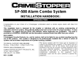
Programming Note:
P
The default wire function settings are listed next
to the wire color. Wires shown with can be
programmed to perform different functions.
Refer to the Feature Programming section to
change the default setting.
P
P
P
Security Trigger Zones
IfthesecuritysystemhasbeentriggeredtheLEDwillashoneofthepatternsbelow
indicating the zone.
LED FLASHES TRIGGER ZONE
2 Flashes Hood / Trunk Input
3 Flashes Door Input
4 Flashes Shock Sensor
5 Flashes Ignition Input
Remote Start Shutdown Diagnostics
Iftheremotestartshutsdownorfailstostart,theparkinglightswillashoneofthepatternsbelowindicatingtheshutdowninput.
To manually enter diagnostics and view the last shutdown, turn the ignition ON and press and release the button.
PARKING LIGHT FLASHES SHUTDOWN ZONE
3 Flashes Hood / Brake Input
4 Flashes Remote Start Valet Mode
5 Flashes Manual Transmission Mode not ready
7Flashes Tachnotlearned/CrankAveragenotlearned
Complete guides also available at
www.voxxuniversity.com
**Thisguideisareferenceformodulermwareversion5.0orhigher**

Defaulting All Features: Pressing the button anytime while in any of the feature
bankswilldefaultallfeaturesandreturnyoutofeaturebank2-4 chirps.
NOTE: The system will remain in feature programming mode as long as the ignition is
on, there is no time limit. To exit programming turn the IGNITION OFF.
Manual Feature Programming - Feature Bank 2, 3, 4, & 5
1. Turn the ignition ON.
2. Press and hold the valet/override button.
3. Within 10 seconds the system will chirp (3) three times.
4. Use the valet/override button to advance through each option bank. For
feature programming advance to Feature Bank 2, 3, 4 or 5, which is (4)
four,(5)ve,(6)sixand(7)sevenchirps.
5. Use the transmitter button to scroll through the selections in each
feature bank, the system will chirp to match the feature number.
6. Press the transmitter button or the vehicle brake pedal to change the
desiredfeature.TheLEDwillashindicatingthechangedfeature.
Set Up & Programming
Transmitter Programming - Feature Bank 1
1. Turn the ignition ON.
2. Press and hold the valet/override button.
3. Within 10 seconds the system will chirp (3) three times.
4. Press 1 button of each transmitter you wish to program.
5. The system will respond with 1 chirp for each accepted transmitter.
6. Pressing the override button at anytime during programming will advance to
the next bank.
NOTE: The system will exit transmitter programming after 15 seconds of inactivity.
NOTE: This system has 1 button programming which programs all channels of the
system.
NOTE: The system will hold up to 4 transmitters in memory, programming a 5th
transmitter will erase the oldest transmitter in memory.
NOTE:ThissystemhasPTN-ProgrammedTransmitterNotication.Eachtimethe
ignitionisturnedON,theLEDwillashthenumberoftransmittersprogrammedtothe
system.
Transmitter programming for 2 Car Mode *2 way LCD system only:
1. Enter the transmitter into 2 Car Mode. (Refer to transmitter operation in the
owners manual for 2 car operation)
2. Follow the steps above for transmitter programming.
NOTE: 2 car mode requires an additional security system installed in a second
vehicle.
Refer to transmitter programming.
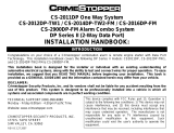
Feature Bank 1 - 3 Chirps
Transm itte r Programming
Feature Bank 2 - 4 Chirps
Security Control
1 LED Flash 2 LED Flash 3 LED Flash 4 LED Flash 5 LED Flash 6 LED Flash
1Silent Choice ON OFF
2Door Locks Active Passive
3System Arming Active Passive
4System Notifications Siren & Horn Siren Only Horn Only
5 Alarm Duration 30 Seconds 60 Seconds
6Security ON OFF
ON
w/ OEM
Re
mote Start
7Anti-Hijack Mode OFF ON
8
Ground While Armed
Orange ( - ) Output
Ground While
Armed
Ground While
Disarmed
9
DBI Port Protocol /
Telematic Port Protocol
DBI /
Voxx Telematic
ADS /
Voxx Telematic
DB
I /
ADS
Telematic
ADS /
ADS Telematic
10 Arm / Disarm Chirps
Standard:
2 - Arm
1 - Disa rm
Inve rted:
1 - Arm
2 - Disarm
11 LED Indicator ON OFF
12 Auto Re-lock OFF Lock Only Arm & Lock
13 Extended Parking Lights OFF After Unlock After Lock
After Lock &
Unlock
14
Parking Light Relay / Trunk ( - )
Output
Standard Inve rted
15 Digital Tilt Sensor N/A
16
Domelight Delay:
Preset Time or Programmable
OFF /
Program
Custom Time
15 Seconds 30 Seconds 45 Seconds60 Seconds 120 Seconds
17
Instant Trigger Input
Blue / White ( - ) Input
Full Trigger
Pre-Warn /
Warn-Away
Va
let Button
I
nput
Feature Bank 3 - 5 Chirps
Output Control
1 LED Flash 2 LED Flash 3 LED Flash 4 LED Flash 5 LED Flash 6 LED Flash
1Lock / Unlock Timing 1 Sec. 3.5 Sec.
1
Sec. Lock,
2x
Unlock
30 Sec. Lock,
2x Unlock
2x Lock,
1 Sec. Unlock
0.5 Sec.
2
Factory Disarm 2
Blue / Green Output
Factory
Disa rm
2nd Unlock
Fa
ctory Disarm
2x
500mS
Factory Disarm
350mS
Factory Disarm
500mS
Factory Disarm
w/ Unlock
Timing
3Ignition Locks OFF Lock / Unlock Lock Only Unlock Only
4 Trunk Output Timing 1 Sec. 10 Sec. 20 Sec.
Latched until
IGN ON
Latched ON
until Button
Press
5Horn Output Timing 16mS 10mS30mS40mS50mS
6Real Panic ON OFF
7
AUX 1
Violet / Black Output
1 Sec. Latched
La
tched until
IG
N ON
Dome Light
Output
Defrost Output
Single Pulse
After Start
Defrost Output
Latched 5 Min
After Start
8
AUX 2
White / Black Output
1 Sec. Latched
La
tched until
IG
N ON
10 Sec.
w/ Arm
10 Sec.
w/ Disarm
L.E.D. Output
9
AUX 3
Gray / Black Output
1 Sec. Latched
La
tched until
IG
N ON
10 Sec.
w/ Arm
10 Sec.
w/ Disarm
L.E.D. Output
10
AUX 4
Orange / Black Output
1 Sec. Latched
La
tched until
IG
N ON
10 Sec.
w/ Arm
10 Sec.
w/ Disarm
L.E.D. Output
11
AUX 5
Pink / Black Output
1 Sec. Latched
La
tched until
IG
N ON
10 Sec.
w/ Arm
10 Sec.
w/ Disarm
L.E.D. Output
Fe
ature Bank 4 - 6 Chirps
Re
mote Start Control
1 LED Flash 2 LED Flash 3 LED Flash 4 LED Flash 5 LED Flash 6 LED Flash
1RS Confirmation Chirp ON OFF
2Run Time 15 Minute s 5 Minutes 10 Minutes 20 Minutes 45 Minutes 60 Minutes
3Running Lights Steady Flashing
4Tach Mode Tach TachlessHybridDBI Port
5Voltage Level High Low
6Crank Time 1.0 Seconds 0.8 Seconds 1.5 Seconds 2.0 Seconds 4.0 Seconds
7Crank Output Averaging Preset Time
8Diesel Delay OFF 10 Sec. Delay 15 Sec. Delay 20 Sec. Delay 45 Sec. Delay 5 Sec. Delay
9Remote Start Activation 2x Start 1x Start
10
Ignition 2 Output
Pink / White
Ignition Accessory Start / Crank
11 Auto Start Interval 3 Hour 2 Hour
12 Turbo Timer OFF 1 Minute3 Minute5 Minute
13 Transmission Mode Automatic Manual
14 Temperature Start OFF 14F 5F -4F 0F -14F
15
Accessory Output
Orange
Accessory Ignition Start / Crank
16 Pulse Outputs with Unlock OFF
IG
N, ACCY,
GW
R
IGN, ACCY,
GWR - Pulse
After Shutdown
17 RS Door Lock Control OFF
Un
lock before
St
art, Lock
Af
ter Start
Unlock Before
Start
Lock After
Start
Lock After
Shutdown
18
Pa
rking Brake Input
Gr
ay / Red ( - ) Input
Pa
rking /
Ha
nd Brake
Foot Brake
Fe
ature Bank 5 - 7 Chirps
Al
ternate Output Control
1 LED Flash 2 LED Flash 3 LED Flash 4 LED Flash 5 LED Flash 6 LED Flash
1
Fa
ctory Disarm
L
t Green / Black Output
Pu
lse Before
St
art / During
Un
lock
Gr
ound While
R
unning
Ignition Accessory
Pulse During
Crank
Pulse Before
Start / During
Unlock - Uses
Unlock Timing
2
Factory Arm
Lt Blue Output
Pu
lse After
St
art / During
Lo
ck
Gr
ound While
R
unning
Ignition Accessory
Pulse During
Crank
Pulse After
Start / During
Lock - Uses
Lock Timing
3
P
ulse After Shutdown
Gr
een / White Output
Pu
lse After
Sh
utdown
Gr
ound While
R
unning
Ignition Accessory
Pulse During
Crank
Pulse After
Shutdown 2
Sec. Delay
4
P
ulse During Crank
Bl
ack / Yellow Output
Pu
lse During
Cr
ank
Gr
ound While
R
unning
Ignition Accessory
Pulse Before
Start / During
Unlock
Pulse Before
Start / During
Unlock - Uses
Unlock Timing
PC Based Feature Programming / Firmware Updates
WhenusingtheNEWCodeAlarmUtilityAppalongwithaVEPROGProgrammingtoolyoumayprogramselectablefeaturesorupdatethermwareofthismodule.Refertofull
installation guide for additional detail.
1. To download the Code Alarm Utility App visit the Voxx University website at voxxuniversity.com (registration/login required).
2. Select VOXXTECH and locate the utility app under the heading Software Downloads.
3. The Code Alarm Utility App download includes both the CA Utility app and necessary VEPROG drivers.
4. Install both items before attempting to update modules.
Technical Support (800) 421-3209
or visit
www.voxxuniversity.com
Programming Update Notice: Firmware version 5.0 or later.
Programming Update Notice: Firmware version 5.0 or later.
/