Hitachi DH 45ME Safety Instructions And Instruction Manual
- Category
- Power tools
- Type
- Safety Instructions And Instruction Manual

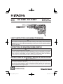
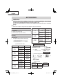
Model
Rotary Hammer
Modèle
Marteau rotatif
Modelo
Martillo perforador
DH 45ME
•
DH 45MEY
DOUBLE INSULATION
DOUBLE ISOLATION
AISLAMIENTO DOBLE
INSTRUCTIONS DE SECURITE ET MODE D’EMPLOI
AVERTISSEMENT
Une utilisation INCORRECTE OU DANGEREUSE de cet outil motorisé peut entraîner la
mort ou de sérieuses blessures corporelles!
Ce mode d’emploi contient d’importantes informations à propos de la sécurité de ce produit.
Prière de lire et de comprendre ce mode d’emploi AVANT d’utiliser l’outil motorisé. Garder ce
mode d’emploi à la disponibilité des autres utilisateurs et propriétaires avant qu’ils utilisent
l’outil motorisé. Ce mode d’emploi doit être conservé dans un endroit sûr.
SAFETY INSTRUCTIONS AND INSTRUCTION MANUAL
WARNING
IMPROPER OR UNSAFE use of this power tool can result in death or serious bodily injury!
This manual contains important information about product safety. Please read and
understand this manual BEFORE operating the power tool. Please keep this manual
available for other users and owners before they use the power tool. This manual should be
stored in safe place.
INSTRUCCIONES DE SEGURIDAD Y MANUAL DE INSTRUCCIONES
ADVERTENCIA
¡La utilización INAPROPIADA O PELIGROSA de esta herramienta eléctrica puede resultar
en lesiones de gravedad o la muerte!
Este manual contiene información importante sobre la seguridad del producto. Lea y com-
prenda este manual ANTES de utilizar la herramienta eléctrica. Guarde este manual para
que puedan leerlo otras personas antes de utilizar la herramienta eléctrica. Este manual
debe ser guardado en un lugar seguro.

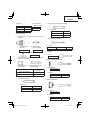
CONTENTS
Page
IMPORTANT SAFETY INFORMATION .......................3
MEANINGS OF SIGNAL WORDS ...............................3
SAFETY ...........................................................................3
GENERAL POWER TOOL SAFETY WARNINGS ........3
SPECIFIC SAFETY RULES AND SYMBOLS ..............4
DOUBLE INSULATION FOR SAFER OPERATION
......5
FUNCTIONAL DESCRIPTION ........................................6
NAME OF PARTS ........................................................6
SPECIFICATIONS .......................................................7
Page
ASSEMBLY AND OPERATION .......................................7
APPLICATIONS ...........................................................7
PRIOR TO OPERATION ..............................................7
HOW TO USE ..............................................................9
USING DRILL CHUCK, CHUCK ADAPTOR ..............12
HOW TO USE THE CORE BIT ..................................12
MAINTENANCE AND INSPECTION ............................13
ACCESSORIES.............................................................14
STANDARD ACCESSORIES.....................................14
OPTIONAL ACCESSORIES ......................................14
PART LIST .....................................................................50
English
TABLE DES MATIERES
Page
INFORMATIONS IMPORTANTES
DE SÉCURITÉ ......................................................17
SIGNIFICATION DES MOTS
D’AVERTISSEMENT .................................................17
SECURITE ....................................................................17
AVERTISSEMENTS DE SÉCURITÉ GÉNÉRAUX
CONCERNANT LES OUTILS ÉLECTRIQUES
.........17
REGLES DE SECURITE SPECIFIQUES ET
SYMBOLES ..........................................................19
DOUBLE ISOLATION POUR UN FONCTIONNEMENT
PLUS SUR ............................................................20
DESCRIPTION FONCTIONNELLE ..............................21
NOM DES PARTIES ..................................................21
SPECIFICATIONS .....................................................21
Page
ASSEMBLAGE ET FONCTIONNEMENT .....................22
APPLICATIONS .........................................................22
AVANT L’UTILISATION ..............................................22
UTILISATION ............................................................. 24
UTILISATION DU MANDRIN PORTE-FORET
ET DU RACCORD DE MANDRIN .........................27
COMMENT UTILISER LA COURONNE ....................27
ENTRETIEN ET INSPECTION......................................29
ACCESSOIRES.............................................................30
ACCESSOIRES STANDARD.....................................30
ACCESSOIRES SUR OPTION ..................................30
LISTE DES PIÈCES ......................................................50
Français
Página
INFORMACIÓN IMPORTANTE SOBRE
SEGURIDAD .........................................................33
SIGNIFICADO DE LAS PALABRAS DE
SEÑALIZACIÓN ....................................................33
SEGURIDAD .................................................................33
ADVERTENCIAS DE SEGURIDAD GENERAL
DE LA HERRAMIENTA ELÉCTRICA ....................33
NORMAS Y SÍMBOLOS ESPECÍFICOS DE
SEGURIDAD .........................................................35
AISLAMIENTO DOBLE PARA OFRECER UNA
OPERACIÓN MÁS SEGURA ................................36
DESCRIPCIÓN FUNCIONAL .......................................37
NOMENCLATURA ....................................................37
ESPECIFICACIONES ................................................ 37
Página
MONTAJE Y OPERACIÓN ............................................38
APLICACIONES ........................................................38
ANTES DE LA OPERACIÓN .....................................38
MODO DE UTILIZACIÓN ..........................................40
UTILIZACIÓN DEL PORTABARRENAS Y DEL
ADAPTADOR PARA PORTABARRENAS .............43
MODO DE USAR LA BARRENA TUBULAR..............43
MANTENIMIENTO E INSPECCIÓN .............................45
ACCESORIOS...............................................................46
ACCESORIOS ESTÁNDAR ......................................46
ACCESORIOS OPCIONALES ..................................46
LISTA DE PIEZAS .........................................................50
Español
ÍNDICE

3
English
IMPORTANT SAFETY INFORMATION
Read and understand all of the safety precautions, warnings and operating instructions in the Instruction Manual before
operating or maintaining this power tool.
Most accidents that result from power tool operation and maintenance are caused by the failure to observe basic safety
rules or precautions. An accident can often be avoided by recognizing a potentially hazardous situation before it occurs,
and by observing appropriate safety procedures.
Basic safety precautions are outlined in the “SAFETY” section of this Instruction Manual and in the sections which contain
the operation and maintenance instructions.
Hazards that must be avoided to prevent bodily injury or machine damage are identifi ed by WARNINGS on the power tool
and in this Instruction Manual.
NEVER use this power tool in a manner that has not been specifi cally recommended by HITACHI.
MEANINGS OF SIGNAL WORDS
WARNING indicates a potentially hazardous situations which, if ignored, could result in death or serious injury.
CAUTION indicates a potentially hazardous situations which, if not avoided, may result in minor or moderate injury, or
may cause machine damage.
NOTE emphasizes essential information.
SAFETY
GENERAL POWER TOOL SAFETY WARNINGS
WARNING:
Read all safety warnings and all instructions.
Failure to follow the warnings and instructions may result in electric shock, fi re and/or serious injury.
Save all warnings and instructions for future reference.
The term “power tool” in the warnings refers to your mains-operated (corded) power tool or battery-operated
(cordless) power tool.
1) Work area safety
a) Keep work area clean and well lit.
Cluttered or dark areas invite accidents.
b) Do not operate power tools in explosive
atmospheres, such as in the presence of
fl ammable liquids, gases or dust.
Power tools create sparks which may ignite the
dust or fumes.
c) Keep children and bystanders away while
operating a power tool.
Distractions can cause you to lose control.
2) Electrical safety
a) Power tool plugs must match the outlet.
Never modify the plug in any way.
Do not use any adapter plugs with earthed
(grounded) power tools.
Unmodified plugs and matching outlets will
reduce risk of electric shock.
b) Avoid body contact with earthed or grounded
surfaces such as pipes, radiators, ranges and
refrigerators.
There is an increased risk of electric shock if
your body is earthed or grounded.
c) Do not expose power tools to rain or wet
conditions.
Water entering a power tool will increase the
risk of electric shock.
d) Do not abuse the cord. Never use the cord for
carrying, pulling or unplugging the power tool.
Keep cord away from heat, oil, sharp edges
or moving parts.
Damaged or entangled cords increase the risk
of electric shock.
e) When operating a power tool outdoors, use
an extension cord suitable for outdoor use.
Use of a cord suitable for outdoor use reduces
the risk of electric shock.
f) If operating a power tool in a damp location
is unavoidable, use a residual current
device (RCD) protected supply.
Use of an RCD reduces the risk of electric shock.
3) Personal safety
a) Stay alert, watch what you are doing and use
common sense when operating a power tool.
Do not use a power tool while you are tired
or under the influence of drugs, alcohol or
medication.

4
English
A moment of inattention while operating power
tools may result in serious personal injury.
b) Use personal protective equipment. Always
wear eye protection.
Protective equipment such as dust mask, non-
skid safety shoes, hard hat, or hearing protection
used for appropriate conditions will reduce
personal injuries.
c) Prevent unintentional starting. Ensure the
switch is in the off -position before connecting
to power source and/or battery pack, picking
up or carrying the tool.
Carrying power tools with your finger on the
switch or energising power tools that have the
switch on invites accidents.
d) Remove any adjusting key or wrench before
turning the power tool on.
A wrench or a key left attached to a rotating part of
the power tool may result in personal injury.
e) Do not overreach. Keep proper footing and
balance at all times.
This enables better control of the power tool in
unexpected situations.
f) Dress properly. Do not wear loose clothing or
jewellery. Keep your hair, clothing and gloves
away from moving parts.
Loose clothes, jewellery or long hair can be
caught in moving parts.
g) If devices are provided for the connection of
dust extraction and collection facilities, ensure
these are connected and properly used.
Use of dust collection can reduce dust-related
hazards.
4) Power tool use and care
a) Do not force the power tool. Use the correct
power tool for your application.
The correct power tool will do the job better and
safer at the rate for which it was designed.
b) Do not use the power tool if the switch does
not turn it on and off .
Any power tool that cannot be controlled with
the switch is dangerous and must be repaired.
c) Disconnect the plug from the power source
and/or the battery pack from the power tool
before making any adjustments, changing
accessories, or storing power tools.
Such preventive safety measures reduce the
risk of starting the power tool accidentally.
d) Store idle power tools out of the reach of
children and do not allow persons unfamiliar
with the power tool or these instructions to
operate the power tool.
Power tools are dangerous in the hands of
untrained users.
e) Maintain power tools. Check for misalignment
or binding of moving parts, breakage of parts
and any other condition that may aff ect the
power tool’s operation.
If damaged, have the power tool repaired
before use.
Many accidents are caused by poorly maintained
power tools.
f) Keep cutting tools sharp and clean.
Properly maintained cutting tools with sharp
cutting edges are less likely to bind and are
easier to control.
g) Use the power tool, accessories and tool bits
etc. in accordance with these instructions,
taking into account the working conditions
and the work to be performed.
Use of the power tool for operations different
from those intended could result in a hazardous
situation.
5) Service
a) Have your power tool serviced by a qualifi ed
repair person using only identical replacement
parts.
This will ensure that the safety of the power tool
is maintained.
SPECIFIC SAFETY RULES AND SYMBOLS
1. Wear ear protectors.
Exposure to noise can cause hearing
loss.
2. Use auxiliary handles, if supplied with the tool.
Loss of control can cause personal injury.
3. Hold power tools by insulated gripping surfaces
when performing an operation where the cutting
tool may contact hidden wiring or its own cord.
Cutting accessory contacting a “live” wire may make
exposed metal parts of the power tool “live” and could
give the operator an electric shock.
4. NEVER touch the tool bit with bare hands after
operation.
5. NEVER wear gloves made from materials likely to roll
up such as cotton, wool, cloth or string, etc.
6. ALWAYS attach the side handle and securely grip
the Rotary Hammer.
7. NEVER touch moving parts.
NEVER place your hands, fi ngers or other body parts
near the tool’s moving parts.
8. NEVER operate without all guards in place.
NEVER operate this tool without all guards or safety
features in place and in proper working order. If
maintenance or servicing requires the removal of a
guard or safety feature, be sure to replace the guard
or safety feature before resuming operation of the
tool.
9. Use right tool.
Don’t force small tool or attachment to do the job of a
heavy-duty tool.

5
English
Don’t use tool for purpose not intended —for
example— don’t use circular saw for cutting tree
limbs or logs.
10. NEVER use a power tool for applications other
than those specifi ed.
NEVER use a power tool for applications other than
those specifi ed in the Instruction Manual.
11. Handle tool correctly.
Operate the tool according to the instructions
provided herein. Do not drop or throw the tool.
NEVER allow the tool to be operated by children,
individuals unfamiliar with its operation or
unauthorized personnel.
12. Keep all screws, bolts and covers tightly in
place.
Keep all screws, bolts, and plates tightly mounted.
Check their condition periodically.
13. Do not use power tools if the plastic housing or
handle is cracked.
Cracks in the tool’s housing or handle can lead to
electric shock. Such tools should not be used until
repaired.
14. Blades and accessories must be securely
mounted to the tool.
Prevent potential injuries to youself or others. Blades,
cutting implements and accessories which have
been mounted to the tool should be secure and tight.
15. Keep motor air vent clean.
The tool’s motor air vent must be kept clean so that
air can freely fl ow at all times. Check for dust build-up
frequently.
16. Operate power tools at the rated voltage.
Operate the power tool at voltages specified on its
nameplate.
If using the power tool at a higher voltage than the
rated voltage, it will result in abnormally fast motor
revolution and may damage the unit and the motor
may burn out.
17. NEVER use a tool which is defective or operating
abnormally.
If the tool appears to be operating unusually, making
strange noises, or otherwise appears defective, stop
using it immediately and arrange for repairs by a
Hitachi authorized service center.
18. NEVER leave tool running unattended. Turn
power off .
Don’t leave tool until it comes to a complete stop.
19. Carefully handle power tools.
Should a power tool be dropped or struck against
hard materials inadvertently, it may be deformed,
cracked, or damaged.
20. Do not wipe plastic parts with solvent.
Solvents such as gasoline, thinner benzine, carbon
tetrachloride, and alcohol may damage and crack
plastic parts. Do not wipe them with such solvents.
Wipe plastic parts with a soft cloth lightly dampened
with soapy water and dry thoroughly.
21. ALWAYS wear eye protection that meets the
requirement of the latest revision of ANSI
Standard Z87.1.
22. ALWAYS be careful with buried object such as an
underground wiring.
Touching live wiring or electric cable with this tool
may result in electric shock.
Confirm before use whether hidden objects are
present, such as electric cables within the wall, fl oor
or ceiling.
23. Defi nitions for symbols used on this tool
V .................volts
Hz ...............hertz
A .................amperes
n
o
...............no load speed
W ................watt
..............Class
II
Construction
---/min .........revolutions per minute
...............Alternating current
DOUBLE INSULATION FOR SAFER
OPERATION
To ensure safer operation of this power tool, HITACHI has
adopted a double insulation design. “Double insulation”
means that two physically separated insulation systems
have been used to insulate the electrically conductive
materials connected to the power supply from the outer
frame handled by the operator. Therefore, either the
symbol “ ” or the words “Double insulation” appear on
the power tool or on the nameplate.
Although this system has no external grounding, you must
still follow the normal electrical safety precautions given in
this Instruction Manual, including not using the power tool
in wet environments.
To keep the double insulation system effective, follow
these precautions:
䡬
Only HITACHI AUTHORIZED SERVICE CENTER
should disassemble or assemble this power tool, and
only genuine HITACHI replacement parts should be
installed.
䡬
Clean the exterior of the power tool only with a soft
cloth moistened with soapy water, and dry thoroughly.
Never use solvents, gasoline or thinners on plastic
components; otherwise the plastic may dissolve.

6
English
SAVE THESE INSTRUCTIONS
AND
MAKE THEM AVAILABLE TO OTHER USERS
AND
OWNERS OF THIS TOOL!
FUNCTIONAL DESCRIPTION
NOTE:
The information contained in this Instruction Manual is designed to assist you in the safe operation and maintenance
of the power tool.
NEVER operate, or attempt any maintenance on the tool unless you have first read and understood all safey
instructions contained in this manual.
Some illustrations in this Instruction Manual may show details or attachments that diff er from those on your own
power tool.
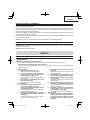
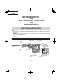
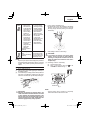
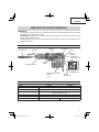
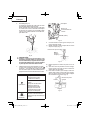
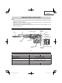
NAME OF PARTS
Fig. 1
Stopper
Grip
Switch trigger
Side handle
Nameplate
Continuous operation
button
Selector lever
Drill bit
Rotation speed
selector switch
Power lamp
Display lamp
Handle

7
English
ASSEMBLY AND OPERATION
APPLICATIONS
Rotation and hammering function
䡬
Drilling anchor holes
䡬
Drilling holes in concrete
Hammering function only
䡬
Crushing concrete, chipping, digging, and squaring
(by applying optional accessories)
PRIOR TO OPERATION
1. Power source
Ensure that the power source to be utilized conforms
to the power source requirements specified on the
product nameplate.
2. Power switch
Ensure that the switch is in the OFF position. If the
plug is connected to a receptacle while the switch is
in the ON position, the power tool will start operating
immediately and can cause serious injury.
3. Extension cord
When the work area is far away from the power
source, use an extension cord of suffi cient thickness
and rated capacity. The extension cord should be
kept as short as practicable.
WARNING:
Damaged cord must be replaced
or repaired.
4. Check the receptacle
If the receptacle only loosely accepts the plug, the
receptacle must be repaired. Contact a licensed
electrician to make appropriate repairs.
If such a faulty receptacle is used, it may cause
overheating, resulting in a serious hazard.
5. Confi rming condition of the environment:
Confi rm that the work site is placed under appropriate
conditions conforming to prescribed precautions.
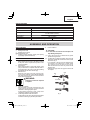
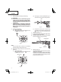
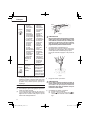
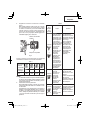
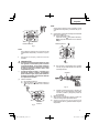
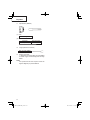
6. How to install tool
CAUTION:
For tools such as a drill bit and a bull point, use
only Hitachi genuine parts.
(1) Clean, then smear the tool shank with the grease
provided in the green tube.
(2) To attach the tool (SDS max shank), insert it into the
hole until it contacts the innermost end of the hole as
illustrated in Fig. 2.
If you continue to turn the tool with slight pressure,
you can feel a spot where there is a hitch. At that
spot, pull the grip to the direction of an arrow
mark and insert the tool all the way until it hits the
innermost end.
Releasing the grip reverts the grip and secures the
tool in place.
Grip
Tool
Fig. 2
Tool shank
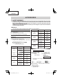
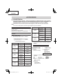
SPECIFICATIONS
Model DH45ME DH45MEY
Motor Brushless motor
Power Source Single-Phase, 120 V 60 Hz
Capacity
Drill Bit: 1-3/4" (45 mm)
Core Bit: 4-29/32" (125 mm)
No-Load Speed 120 – 270/min
Full-load Blow 1,000 – 2,500/min
Weight 19.8 lbs (9.0 kg) 20.9 lbs (9.5 kg)

8
English
(3) Pull the tool to make sure it is locked completely.
(4) To remove the tool, fully pull the grip in the direction
of the arrow and pull out the tool.
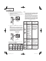
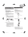
7. Power lamp
The power lamp lights up when the power cord is
plugged into an electrical outlet. (Fig. 3)
Power lamp
Fig. 3
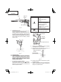
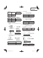
8. Regulating the number of rotations and hammering
(Fig. 4)
This Rotary Hammer is equipped with a built-in
electronic control circuit that can adjust and regulate
the number of rotations and times of hammering.
This Rotary Hammer can be used by adjusting the
rotation speed selector switch, depending upon
the contents of operation, such as boring holes into
fragile materials, chipping, centering, etc.
Fig. 4
Rotation speed
selector switch
Display lamp
Pressing the rotation speed selector switch switches
rotation speeds as shown in Table 1.
Table 1
Display lamp
sequence
Full-load
speed
120 170 220 270
Impacts per
Minute
1,200 1,600 2,100 2,500
NOTE:
The rotation speed cannot be changed by pressing
the rotation speed selector switch while the motor is
rotating. To change speeds, switch off the tool fi rst.
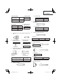
9. About the protection function
This tool has a built-in protection circuit for preventing
damage to the unit in the event of an abnormality.
Depending on the nature of the abnormality, the
display lamp will fl ash as shown in Table 2 and the
unit will cease to operate. In such cases, verify the
problem indicated by the fl ashing and take whatever
steps are necessary to correct the problem.
Table 2
Display
lamp
fl ashing
Cause Solution
Flash
or
The tool’s
temperature
increase protection
function gradually
reduced the
rotation speed
as the internal
temperature of the
tool approached
the specifi ed
temperature range
for automatic
shutdown.
(Power regulation
function)
* The power
regulation
function will not
activate if only
one or two of the
display lamp bars
are lighting.
The tool will return to
normal power once the
temperature is lowered
by reducing its load.
Continued operation
may result in automatic
shutdown by the tool’s
temperature increase
protection function.
(See row below)
Flash
Internal
temperature has
risen beyond the
unit’s specifi ed
temperature
(Temperature
increase protection
function)
Turn off the unit
and allow it to cool
down for about 15 to
30 minutes.
When the temperature
goes down, press the
rotation speed selector
switch to recover.
Flash
Excessive pressure
applied to the tool
has resulted in an
overload.
(Overload
protection function)
Press the rotation
speed selector switch
to recover. Try to avoid
tasks that will apply
excess pressure to the
unit.

9
English
NOTE:
Repair may be required if the display lamp continues
to fl ash after taking all necessary steps to correct the
problem. If the problem persists, please arrange for
repairs.
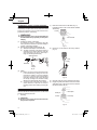
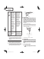
HOW TO USE
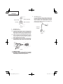
1. How to drill holes (Fig. 5)
(1) Pull the switch trigger after applying the drill bit tip to
the drilling position.
(2) It is unnecessary to forcibly press the Rotary Hammer
main body. It is suffi cient to slightly press the rotary
hammer to an extent that clips are freely discharged.
Fig. 5
CAUTION:
Although this machine is equipped with a slip
clutch, if the drill bit becomes bound in concrete
or other material, the resultant stoppage of the
drill bit could cause the machine body to turn in
reaction. Ensure that the main handle and side
handle are gripped fi rmly during operation.
2. How to chisel or demolish (Fig. 6)
By applying the tool tip to the chiseling or demolishing
position, operate the rotary hammer by utilizing
its empty weight. Forcible pressing or thrusting is
unnecessary.
Fig. 6
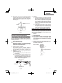
3. When drilling at “rotation + hammering”
CAUTION:
If you switch the selector lever during motor
rotation, the tool can start to rotate abruptly,
resulting in unexpected accidents. Be sure to
switch the selector lever when the motor is at a
complete stop.
(1) Switching to “rotation + hammering”
(a) Turn the selector lever.
(b) Align of the selector lever and of the
crank cover as illustrated in Fig. 7.
Fig. 7
Selector lever
NOTE:
Turn the selector lever to check if it is completely
locked and make sure that it does not turn.
Flash
1
Tool fails to
startup or has
shut down due
to the unit being
connected to a
power source
whose voltage
is either too
high or too low.
2
Tool has shut
down due to a
voltage signal
read error that
occurred from
the unit’s power
cord being
plugged in and
out at short
intervals.
(Circuit protection
function)
1
Connect the unit
to a power supply
matching the input
voltage specifi ed
on the nameplate.
Press the rotation
speed selector
switch to recover.
2
Allow for an interval
of 3 seconds
or more when
plugging the power
cord in and out.
Press the rotation
speed selector
switch to recover.
Flash
Sensor signal read
error.
(Control monitoring
function)
Press the rotation
speed selector switch
to recover. Repair may
be required if this error
continuously occurs.

10
English
4. When chipping and shredding at “hammering”
CAUTION:
䡬
If the selector lever is switched during motor
rotation, the tool can start to rotate abruptly,
resulting in unexpected accidents. Make sure to
switch the selector lever when the motor is at a
complete stop.
䡬
If the bull point or cold chisel is used at the
position of “rotation + hammering”, the tool can
start to rotate, resulting in unexpected accidents.
Make sure that they are used at the positon of
“hammering”.
(1) Switching to “hammering”
(a) Turn the selector lever.
(b) Align of the selector lever and of the crank
cover as illustrated in Fig. 8.
Fig. 8
Selector lever
NOTE:
Turn the selector lever to check if it is completely
locked and make sure that it does not turn.
(2) When fi xing working positions of tools such as cold
chisel, etc.,
(a) Turn the selector lever.
Align of the selector lever and of the crank
cover as illustrated in Fig. 9.
Fig. 9
Selector lever
(b) Turn the grip or the tool as illustrated in Fig. 10
and fi x the tool to the desired working direction.
Grip
Fig. 10
(c) Switch the selector lever to “hammering”
according to the procedures mentioned in the
above item (1) and secure the position of the
tool.
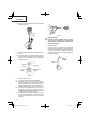
5. Install the stopper (Fig. 11)
(1) Loosen the wing bolt, and insert the stopper into the
mounting hole on the side handle.
(2) Adjust the stopper position according to the depth of
the hole and tighten the wing bolt securely.
Fig. 11
Stopper
Mounting hole
Wing bolt
6. Warming up (Fig. 12)
The grease lubrication system in this unit may require
warming up in cold regions.
Position the end of the bit so makes contact with the
concrete, turn on the switch and perform the warming
up operation. Make sure that a hitting sound is
produced and then use the unit.

11
English
Fig. 12
CAUTION:
When the warming up operation is performed,
hold the side handle and the main body securely
with both hands to maintain a secure grip and
be careful not to twist your body by the jammed
drill bit.
7. Using the Continuous operation button
When operating this machine in “ hammering”
mode, you can set it to remain ON after the switch
is released by pressing the Continuous operation
button.
Selector lever Operation
“hammering”
Press the Continuous operation
button
(Blue LED will light up)
[To cancel Continuous operation]
Press one of the following to cancel
continuous operation:
•
Press the Continuous operation
button
•
Press the switch
“rotation +
hammering”
Continuous operation button
cannot be used for this mode
Fig. 13
Switch
Continuous
operation
button
LED (Blue)
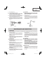
8. How to use the drill bit (taper shank) and the taper
shank adaptor.
(1) Install drill bit with taper shank in the taper shank
adaptor. (Fig. 14)
Fig. 14
Drill bit
(Taper shank)
Taper shank adaptor
(2) Turn the power on and drill a base hole.
(3) After cleaning out dust with a syringe, attach the
plug to the anchor tip and drive in the anchor with a
manual hammer.
(4) To remove the drill bit with taper shank, insert a
cotter into the slot of the taper shank adaptor, place
supports under the Rotary Hammer and tap the
cotter with a manual hammer. (Fig. 15)
Taper shank
adaptor
Cotter
Support
Fig. 15

12
English
USING DRILL CHUCK, CHUCK ADAPTOR
Note that this machine can be used at “rotation only”
if separately sold parts such as drill chuck and chuck
adaptor are attached. Use it with the selector lever
positioned at “rotation + hammering”.
WARNING:
During operation, be sure to grip the handle and
the side handle fi rmly to prevent your body from
swaying.
(1) Switching to “rotation + hammering”
For switching to “rotation + hammering”, follow the
same procedures mentioned in [3. When drilling at
“rotation + hammering”] in Page 9.
(2) Attaching chuck adaptor to drill chuck (Fig. 16)
(a) Attach the chuck adaptor to the drill chuck.
(b) The SDS max shank of the chuck adaptor is
equivalent to the drill bit. Therefore, follow the
same procedure as [6. How to install tool] in
Page 7 for attaching and detaching.
Drill chuck
Grip
Fig. 16
SDS max shank
Chuck
adaptor
(3) Drilling
(a) Even if you apply more-than-required pressure
to the machine body, drilling can never be
performed as quickly as you expect. Applying
more force or pressure to the machine body
than what is needed, on the contrary, damages
the drill tip, resulting in the declined working
effi ciency and shortened life of this machine.
(b) A drill can snap sometimes when drilling is
almost finished. It is important to relax your
thrusting pressure when drilling is nearing the
end.
HOW TO USE THE CORE BIT
When boring penetrating large hole use the core bit. At
that time use with the center pin and the core bit shank
provided as optional accessories.
1. Mounting
CAUTION:
Be sure to turn power OFF and disconnect the
plug from the receptacle.
(1) Mount the core bit to the core bit shank. (Fig. 17)
Lubricate the thread of the core bit shank to facilitate
disassembly.
Core bit
Core bit shank
Fig. 17
(2) Mount the core bit shank to the Rotary Hammer.
(Fig. 18)
Fig. 18
(3) Insert the center pin into the guide plate until it stops.
(4) Engage the guide plate with the core bit, and turn the
guide plate to left or right so that it does not fall even
if it faces downward. (Fig. 19)
Fig. 19
Center pin
Core bit
Core bit tip
Guide plate

13
English
2. How to bore (Fig. 20)
(1) Connect the plug to the receptacle.
(2) A spring is installed in the center pin. Push it lightly
to the wall or the fl oor straight. Connect all over the
surface of the core bit tip and start operating.
(3) When boring about 3/16” (5 mm) in depth the position
of the hole will establish. Bore after that removing the
center pin and the guide plate from core bit.
(4) Application of excessive force will not only expedite
the work, but will deteriorate the tip edge of the drill
bit, resulting in reduced service life of the rotary
hammer.
Fig. 20
CAUTION:
When removing the center pin and the guide
plate, turn OFF the switch and disconnect the
plug from the receptacle.
3. Dismounting (Fig. 21)
Remove the core bit shank from the rotary hammer
and strike the head of the core bit shank strongly two
or three times with a manual hammer holding the
core bit, then the thread becomes loose and the core
bit can be removed.
Core bit
shank
Fig. 21
MAINTENANCE AND INSPECTION
WARNING:
Be sure to switch power OFF and disconnect the plug from the receptacle during maintenance and inspection.
1. Inspecting the drill bits
Since use of a dull tool will cause motor malfunctioning
and degraded efficiency, replace the drill bit with a
new one or resharpening without delay when abrasion
is noted.
2. Inspecting the screws
Regularly inspect all screws and ensure that they are
properly tightened. Should any of the screws be loose,
retighten them immediately.
WARNING:
Using this Rotary Hammer with loosen screws is
extremely dangerous.
3. Maintenance of the motor
The motor unit is the very “heart” of the power tool.
Exercise due care to ensure the motor does not
become damaged and/or wet with oil or water.
4. Grease replacement
This Rotary Hammer is full air-tight construction to
protect against dust and to prevent lubricant leakage.
Therefore, this Rotary Hammer can be used without
lubrication for long periods. Replace the grease as
described below.
䡬
Grease Replacement Period
After purchase, replace grease after every 6 months
of usage. Ask for grease replacement at the nearest
authorized Service Center.
5. Service and repairs
All quality power tools will eventually require servicing
or replacement of parts because of wear from normal
use. To assure that only authorized replacement
parts will be used, all service and repairs must be
performed by a HITACHI AUTHORIZED SERVICE
CENTER, ONLY.
6. Service parts list
CAUTION:
●
Repair, modification and inspection of Hitachi
Power Tools must be carried out by a Hitachi
Authorized Service Center.
This Parts List will be helpful if presented with
the tool to the Hitachi Authorized Service Center
when requesting repair or other maintenance.
In the operation and maintenance of power
tools, the safety regulations and standards
prescribed in each country must be observed.
MODIFICATIONS:
Hitachi Power Tools are constantly being improved
and modifi ed to incorporate the latest technological
advancements.
Accordingly, some parts may be changed without
prior notice.

14
English
ACCESSORIES
WARNING:
ALWAYS use Only authorized HITACHI replacement parts and accessories. NEVER use replacement parts
or accessories which are not intended for use with this tool. Contact HITACHI if you are not sure whether
it is safe to use a particular replacement part or accessory with your tool.
The use of any other attachment or accessory can be dangerous and could cause injury or mechanical
damage.
NOTE:
Accessories are subject to change without any obligation on the part of the HITACHI.
STANDARD ACCESSORIES
(1) Case (Molded plastic) (Code No. 339060) .................1
(2) Side Handle ..............................................................1
(3) Stopper (Code No. 971786) .......................................1
(4) Hammer Grease A (Code No. 981840) ......................1
OPTIONAL ACCESSORIES.....sold
separately
For accessories in detail please call HITACHI AT
1-800-59-TOOLS
1. Through-hole drilling (Rotation + Hammering)
(1) Drill bit (SDS-max shank)
External dia. Overall lenght Code No.
5/8”
(16 mm)
13-3/8”
(340 mm)
313448
21-1/4”
(540 mm)
313456
3/4”
(19 mm)
13-3/8”
(340 mm)
313449
21-1/4”
(540 mm)
313457
7/8”
(22 mm)
12-5/8”
(320 mm)
313450
20-15/32”
(520 mm)
313458
1”
(25 mm)
12-5/8”
(320 mm)
313451
20-15/32”
(520 mm)
313459
1-1/8”
(28 mm)
14-9/16”
(370 mm)
313452
22-7/16”
(570 mm)
313460
External dia. Overall lenght Code No.
1-1/4”
(32 mm)
14-9/16”
(370 mm)
313453
22-7/16”
(570 mm)
313461
1-1/2”
(38 mm)
14-9/16”
(370 mm)
313454
22-7/16”
(570 mm)
313462
1-9/16”
(40 mm)
14-9/16”
(370 mm)
313455
22-7/16”
(570 mm)
313463
2. Anchor hole drilling (Rotation + Hammering)
(1) Drill Bit
(SDS-plus shank)
(2) Adaptor for SDS-plus
shank bit
(SDS max shank)
Code No. 313465
Adaptor for SDS-plus shank bit
3. Large-dia. hole boring (Rotation + Hammering)
(1) Center pinGuide plate (2) Core bit
(Guide plate)
External dia. of
core bit
Code No.
2” (50 mm) 985388
4-1/8” (105 mm) 955169
(1) Center pin
Code No.
955165
(3) Core bit shank
(SDS max shank)

15
English
7. Groove digging and edging (Hammering)
Overall length Code No.
11” (280 mm) 313473
15-3/4” (400 mm) 313474
(1) Cold chisel
8. Asphalt cutting (Hammering)
(1) Cutter
Overall length Width Code No.
15-3/4” (400 mm) 1-31/32” (50 mm) 313475
9. Digging
(1) Scoop
Code No. 313476
10. Surface Roughing (Hammering)
(1) Bushing Tool
(2) Shank
Code No. 313477
Overall length Code No.
8-21/32” (220 mm) 313479
11. Tamping (Hammering)
(1) Rammer
(2) Shank
Code No. 313478
Overall length Code No.
8-21/32” (220 mm) 313479
(3) Core bit shank
(SDS max shank)
Code No.
313467
(2) Core bit
External dia. Code No.
2” (50 mm) 985380
4-1/8” (105 mm) 955159
5” (125 mm) 987013
Include Guide Plate
4. Drilling holes....For drilling metals and wooden
materials
(1) 13mm drill chuck
(13VLD-D)
Code No. 321813
(2) Chuck adaptor
(SDS max shank)
Code No. 313468
(3) Chuck wrench
Code No. 930515
5. Bolt plaching operation with Chemical Anchor
(Rotation + Hammering)
(1) Chemical Anchor Adaptor
(SDS max shank)
(Standard socket
on the market)
Square dimensions of the side
of the socket installation
Code No.
1/2” (12.7 mm) 313469
3/4” (19.0 mm) 313470
6. Crushing (Hammering)
(1) Bull point
Overall length Code No.
11” (280 mm) 313471
15-3/4” (400 mm) 313472

16
English
12. Syringe (for chip removal)
Code No. 320859
13. Hammer grease A
1.1 lbs (500 g) (in a can) Code No. 980927
0.15 lbs (70 g) (in a green tube) Code No. 308471
NOTE:
Specifications are subject to change without any
obligation on the part of the HITACHI.
Page is loading ...
Page is loading ...
Page is loading ...
Page is loading ...
Page is loading ...
Page is loading ...
Page is loading ...
Page is loading ...
Page is loading ...
Page is loading ...
Page is loading ...
Page is loading ...
Page is loading ...
Page is loading ...
Page is loading ...
Page is loading ...
Page is loading ...
Page is loading ...
Page is loading ...
Page is loading ...
Page is loading ...
Page is loading ...
Page is loading ...
Page is loading ...
Page is loading ...
Page is loading ...
Page is loading ...
Page is loading ...
Page is loading ...
Page is loading ...
Page is loading ...
Page is loading ...
Page is loading ...
Page is loading ...

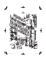
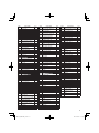
51
ITEM
NO.
PART NAME Q’TY
1 FRONT CAP 1
2 STOPPER RING 1
3 RETAINER WASHER 1
4 GRIP 1
5 RETAINER DAMPER (A) 1
6 BIT LOCK HOLDER 1
7 THRUST PLATE 1
8 RETAINER SPRING 1
9 SPRING HOLDER (A) 1
10 O-RING (S-26) 1
11
HEX. SOCKET HD. BOLT
(W/FLANGE) M5X12
1
12 CYLINDER CASE COVER 1
13 RETAINING RING D35 1
14
RETAINING RING FOR D62
HOLE
1
15
BALL BEARING
6007DDUAV2S
1
16 BEARING WASHER 1
17 OIL SEAL 1
18 CYLINDER CASE 1
19
HEX. SOCKET HD. BOLT
(W/FLANGE) M6X25
4
20 O-RING (F) 1
21
RETAINER DAMPER
HOLDER
1
22 RETAINER DAMPER (B) 1
23 DAMPER SLEEVE 1
24
RETAINER DAMPER
WASHER
1
25 BIT LOCK 2
26 RETAINER SLEEVE 1
27 NEEDLE PIN D6X6 4
28 O-RING (C) 1
29 SECOND HAMMER 1
30 DAMPER WASHER 1
31 DAMPER 1
32 DAMPER HOLDER 1
33 CYLINDER 1
34 STRIKER 1
35 O-RING (E) 1
36 LOCK SPRING WASHER 1
37 SPRING HOLDER (B) 1
38 LOCK SPRING 1
39 LOCK SLEEVE 1
40 CLUTCH SPRING 1
41 CLUTCH 1
42 SLEEVE 1
43 SLIDER 1
44 METAL (A) 1
45 METAL WASHER 1
46 BEVEL GEAR 1
47 O-RING (E) 1
48 PISTON 1
49 PISTON PIN 1
50
CONNECTING ROD ASS'Y
(INCLUD.51)
1
51 NEEDLE BEARING 1
52
HEX. HD. TAPPING SCREW
D5X60
2
53 BEARING WASHER 1
54
BALL BEARING
6201VVCMPS2L
1
55
STATOR SENSOR PCB SET
100V-127V
1
56 HOUSING 1
57 DUST SEAL 1
58 TAIL COVER 1
ITEM
NO.
PART NAME Q’TY
59
HEX. SOCKET HD. BOLT
(W/FLANGE) M5X14
2
60
BALL BEARING
6202DDCMPS2L
1
61 DUST WASHER (B) 1
62
ROTOR ASS'Y
(INCLUD.53,54,60,61)
1
63
CONNECTROLLER
100V-127V (INCLUD.64-66)
1
64 RUBBER SHEET (C) 1
65 RUBBER SHEET (A) 4
66 RUBBER SHEET (D) 1
67 PANEL ASS'Y (INCLUD.65) 1
68
SEAL LOCK HEX. SOCKET
HD. BOLT M5X12
2
69 DISTANCE PIECE (B) 2
70 HANDLE (A) 1
71
FILTER PCB 100V-127V
(INCLUD.72)
1
72 FILTER PACKING 1
73 TRANSATORY UNIT 1
74 HANDLE DAMPER 4
75 HANDLE DAMPER HOLDER 1
76 BELLOWS 1
77 TRIGGER 1
78 SWITCH 1
79 HANDLE (B) 1
80
TAPPING SCREW
(W/FLANGE) D4X25
5
81 PILLAR TERMINAL (A) 1
82 CORD ARMOR D10.7 1
83 CORD CLIP 1
84
TAPPING SCREW
(W/FLANGE) D4X16
2
85 CORD 1
86 HANDLE SHAFT 1
87 BACK COVER 1
88
HEX. SOCKET HD. BOLT
(W/FLANGE) M5X16
4
89 NAME PLATE 1
90 ON LOCK BUTTON 1
91 ON LOCK SPRING 1
92
ON LOCK PCB (A)
(INCLUD.93)
1
93 PACKING (A) 1
94 SIDE HANDLE 1
95 ROLL PIN D2X8 1
96 WING BOLT 1
97 MOUNT 1
98 NUT M6 1
99 HANDLE BOLT 1
100 BAND 1
101 ROLL PIN D2X8 1
102
RETAINING RING FOR D10
SHAFT
1
103 CRANK SHAFT 1
104 FEATHER KEY 3X3X20 1
105
RETAINING RING FOR D40
HOLE
1
106
BALL BEARING
6203DDCMPS2L
1
107 O-RING (S-40) 1
108
SEAL LOCK HEX. SOCKET
HD. BOLT M6X45
4
109 ON LOCK PCB (B) 1
110 FELT PACKING (D) 1
111 CRANK COVER 1
112
HEX. SOCKET HD. BOLT
(W/FLANGE) M5X18
4
ITEM
NO.
PART NAME Q’TY
113 CHANGE LEVER 1
114 LEVER SPRING 1
115 STEEL BALL D4.76 1
116 O-RING (S-18) 1
117 LEVER SHAFT HOLDER 1
118
RETAINING RING FOR D20
SHAFT
1
119 O-RING (I.D 74.5) 1
120 CHANGE PLATE 1
121 FELT PACKING (B) 1
122 VALVE 1
123 FELT PACKING (A) 1
124 CRANK CASE 1
125 OIL SEAL (A) 1
126
SLIP CLUTCH ASS'Y
(INCLUD.125-127,129-137)
1
127 BEVEL PINION 1
128 FEATHER KEY 3X3X8 1
129 COLLAR 1
130
BALL BEARING
6002DDCMPS2L
1
131 WASHER 1
132 WASHER (A) 1
133 GEAR HOLDER 1
134 NEEDLE 10
135 SPRING (C) 10
136 SECOND GEAR 1
137 SPACER 1
138
BALL BEARING
629VVC2PS2L
1
139 BEARING WASHER (C) 1
140 OIL SEAL (A) 1
141 FIRST GEAR 1
142 SECOND PINION 1
143 NEEDLE BEARING (M661) 1
144 SEAL PACKING 1
145
SEAL LOCK HEX. SOCKET
HD. BOLT M6X22
2
146 GEAR COVER 1
501
GREASE (A) FOR HAMMER.
HAMMER DRILL (30G)
1
502 CASE (PLASTIC) 1
503 STOPPER ROD 1
Page is loading ...

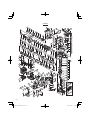
53
ITEM
NO.
PART NAME Q’TY
1 FRONT CAP 1
2 STOPPER RING 1
3 RETAINER WASHER 1
4 GRIP 1
5 RETAINER DAMPER (A) 1
6 BIT LOCK HOLDER 1
7 THRUST PLATE 1
8 RETAINER SPRING 1
9 SPRING HOLDER(A) 1
10 O-RING (S-26) 1
11
HEX. SOCKET HD. BOLT
(W/FLANGE) M5X12
1
12 CYLINDER CASE COVER 1
13 RETAINING RING D35 1
14
RETAINING RING FOR D62
HOLE
1
15
BALL BEARING
6007DDUAV2S
1
16 BEARING WASHER 1
17 OIL SEAL 1
18 CYLINDER CASE 1
19
HEX. SOCKET HD. BOLT
(W/FLANGE) M6X25
4
20 O-RING (F) 1
21
RETAINER DAMPER
HOLDER
1
22 RETAINER DAMPER (B) 1
23 DAMPER SLEEVE 1
24
RETAINER DAMPER
WASHER
1
25 BIT LOCK 2
26 RETAINER SLEEVE 1
27 NEEDLE PIN D6X6 4
28 O-RING (C) 1
29 SECOND HAMMER 1
30 DAMPER WASHER 1
31 DAMPER 1
32 DAMPER HOLDER 1
33 CYLINDER 1
34 STRIKER 1
35 O-RING (E) 1
36 LOCK SPRING WASHER 1
37 SPRING HOLDER (B) 1
38 LOCK SPRING 1
39 LOCK SLEEVE 1
40 CLUTCH SPRING 1
41 CLUTCH 1
42 SLEEVE 1
43 SLIDER 1
44 METAL (A) 1
45 METAL WASHER 1
46 BEVEL GEAR 1
47 O-RING (E) 1
48 PISTON 1
49 PISTON PIN 1
50
CONNECTING ROD ASS'Y
(INCLUDE. 51)
1
51 NEEDLE BEARING 1
52
HEX. HD. TAPPING SCREW
D5X60
2
53 BEARING WASHER 1
54
BALL BEARING
6201VVCMPS2L
1
55
STATOR SENSOR PCB
SET 100V-127V
1
56 HOUSING 1
57 DUST SEAL 1
58 TAIL COVER 1
ITEM
NO.
PART NAME Q’TY
59
HEX. SOCKET HD. BOLT
(W/FLANGE) M5X14
2
60
BALL BEARING
6202DDCMPS2L
1
61 DUST WASHER (B) 1
62
ROTOR ASS'Y (INCLUDE.
53,54,60,61)
1
63
CONTROLLER ASS'Y
(INCLUDE. 64-66)
1
64 RUBBER SHEET (C) 1
65 RUBBER SHEET (A) 4
66 RUBBER SHEET (D) 1
67
PANEL ASS'Y (INCLUDE.
65)
1
68
SEAL LOCK HEX. SOCKET
HD. BOLT M5X12
2
69 DISTANCE PIECE (B) 2
70 HANDLE (A) 1
71
FILTER PCB 100V-127V
(INCLUDE. 93)
1
72 FILTER PACKING 1
73 TRANSATORY UNIT 1
74 HANDLE DAMPER 4
75
HANDLE DAMPER
HOLDER
1
76 BELLOWS 1
77 TRIGGER 1
78 SWITCH 1
79 HANDLE (B) 1
80
TAPPING SCREW
(W/FLANGE) D4X25
5
81 PILLAR TERMINAL (A) 1
82 CORD ARMOR D10.7 1
83 CORD CLIP 1
84
TAPPING SCREW
(W/FLANGE) D4X16
2
85 CORD 1
86 HANDLE SHAFT 1
87 BACK COVER 1
88
HEX. SOCKET HD. BOLT
(W/FLANGE) M5X16
4
89 NAME PLATE 1
90 ON LOCK BUTTON 1
91 ON LOCK SPRING 1
92
ON LOCK PCB (A)
(INCLUDE. 93)
1
93 PACKING (A) 1
94 SIDE HANDLE 1
95 WING BOLT 1
96 ROLL PIN D2X8 1
97 MOUNT 1
98 NUT M6 1
99 HANDLE BOLT 1
100 BAND 1
101 ROLL PIN D2X8 1
102
RETAINING RING FOR D10
SHAFT
1
103 CRANK SHAFT 1
104 FEATHER KEY 3X3X20 1
105
RETAINING RING FOR D40
HOLE
1
106
BALL BEARING
6203DDCMPS2L
1
107 O-RING (S-40) 1
108 CYLINDER O-RING (B) 2
109 WASHER 2
110 WEIGHT 1
111 ON LOCK PCB (B) 1
112 WEIGHT PIN 1
ITEM
NO.
PART NAME Q’TY
113
SEAL LOCK HEX. SOCKET
HD. BOLT M5X30
4
114 LEAF SPRING (A) 2
115 SPRING HOLDER 2
116 BASE 1
117 WEIGHT BUMPER 2
118
SEAL LOCK HEX. SOCKET
HD. BOLT M5X16
2
119 FELT PACKING (D) 1
120 CRANK COVER 1
121
HEX. SOCKET HD. BOLT
(W/FLANGE) M5X18
4
122 CHANGE LEVER 1
123 LEVER SPRING 1
124 STEEL BALL D4.76 1
125 O-RING (S-18) 1
126 LEVER SHAFT HOLDER 1
127
RETAINING RING FOR D20
SHAFT
1
128 O-RING (I.D 74.5) 1
129 CHANGE PLATE 1
130
SEAL LOCK HEX. SOCKET
HD. BOLT M6X45
4
131 FELT PACKING (B) 1
132 VALVE 1
133 FELT PACKING (A) 1
134 CRANK CASE 1
135 OIL SEAL (A) 1
136
SLIP CLUTCH ASS'Y
(INCLUDE. 137-148)
1
137 BEVEL PINION 1
138 FEATHER KEY 3X3X8 1
139 COLLAR 1
140
BALL BEARING
6002DDCMPS2L
1
141 WASHER 1
142 WASHER (A) 1
143 GEAR HOLDER 1
144 NEEDLE 10
145 SPRING (C) 10
146 SECOND GEAR 1
147 SPACER 1
148
BALL BEARING
629VVC2PS2L
1
149 BEARING WASHER (C) 1
150 OIL SEAL (A) 1
151 FIRST GEAR 1
152 SECOND PINION 1
153 NEEDLE BEARING (M661) 1
154 SEAL PACKING 1
155
SEAL LOCK HEX. SOCKET
HD. BOLT M6X22
2
156 GEAR COVER 1
501
GREASE (A) FOR
HAMMER.HAMMER DRILL
(30G)
1
502 CASE (PLASTIC) 1
503 STOPPER ROD 1
Page is loading ...
Page is loading ...

Issued by
Shinagawa Intercity Tower A, 15-1, Konan 2-chome,
Minato-ku, Tokyo 108-6020, Japan
Distributed by
PO Box 970
Braselton, GA 30517
450 Export Blvd. Unit B,
Mississauga ON L5S 2A4
412
Code No. C99713562 M
Printed in Malaysia
Hitachi Koki U.S.A., Ltd.
Hitachi Koki Canada Corp.
Hitachi Koki Co., Ltd.
WARNING:
Some dust created by power sanding, sawing, grinding, drilling, and other construction
activities contains chemicals known to the State of California to cause cancer, birth
defects or other reproductive harm. Some examples of these chemicals are:
●
Lead from lead-based paints,
●
Crystalline silica from bricks and cement and other masonry products, and
●
Arsenic and chromium from chemically-treated lumber.
Your risk from these exposures varies, depending on how often you do this type of
work. To reduce your exposure to these chemicals: work in a well ventilated area, and
work with approved safety equipment, such as those dust masks that are specially
designed to fi lter out microscopic particles.
AVERTISSEMENT:
La poussière résultant d’un ponçage, d’un sciage, d’un meulage, d’un perçage ou de toute
autre activité de construction renferme des produits chimiques qui sont connus par l’Etat de
Californie pour causer des cancers, des défauts de naissance et autres anomalies de re-
production. Nous énumérons ci-dessus certains de ces produits chimiques:
●
Plomb des peintres à base de plomb,
●
Silice cristalline des briques et du ciment et autres matériaux de maçonnerie, et
●
Arsenic et chrome du bois d’oeuvre traité chimiquement.
Le risque d’exposition à ces substances varie en fonction de la fréquence d’exécution
de ce genre de travail. Pour réduire l’exposition à ces produits chimiques, travailler
dans un lieu bien ventilé, et porter un équipement de protection agréé, par exemple
un masque anti-poussière spécialement conçu pour fi lter les particules microscopiques.
ADVERTENCIA:
Algunos polvos creados por el lijado mecánico, el aserrado, el esmerilado, el tal-
adrado y otras actividades de construcción contienen sustancias químicas conocidas
por le Estado de California como agentes cancerígenos, defectos congénitos y otros
daños reproductores. Algunos ejemplos de estas sustancias químicas son:
●
El plomo de las pinturas a base de plomo,
●
El sílice cristalino de los ladrillos y cemento y otros productos de mampostería, y
●
El arsénico y el cromo de la madera tratada químicamente.
El riesgo resultante de la exposición varía según la frecuencia con que se realiza este tipo
de trabajo. Para reducir la exposicíon a esta sustancias químicas: trabaje en un lugar bien
ventilado y realice el trabajo utilizando el equipamiento apropiado, tal como las máscaras
para el polvo especialmente diseñados para eliminar las partículas minúsculas.
-
 1
1
-
 2
2
-
 3
3
-
 4
4
-
 5
5
-
 6
6
-
 7
7
-
 8
8
-
 9
9
-
 10
10
-
 11
11
-
 12
12
-
 13
13
-
 14
14
-
 15
15
-
 16
16
-
 17
17
-
 18
18
-
 19
19
-
 20
20
-
 21
21
-
 22
22
-
 23
23
-
 24
24
-
 25
25
-
 26
26
-
 27
27
-
 28
28
-
 29
29
-
 30
30
-
 31
31
-
 32
32
-
 33
33
-
 34
34
-
 35
35
-
 36
36
-
 37
37
-
 38
38
-
 39
39
-
 40
40
-
 41
41
-
 42
42
-
 43
43
-
 44
44
-
 45
45
-
 46
46
-
 47
47
-
 48
48
-
 49
49
-
 50
50
-
 51
51
-
 52
52
-
 53
53
-
 54
54
-
 55
55
-
 56
56


Hitachi DH 45ME Safety Instructions And Instruction Manual
- Category
- Power tools
- Type
- Safety Instructions And Instruction Manual
Ask a question and I''ll find the answer in the document
Finding information in a document is now easier with AI
in other languages
- français: Hitachi DH 45ME
- español: Hitachi DH 45ME
Related papers
-
Hitachi DH 40MEY User manual
-
-
-
-
Hitachi FDV 16VB2 Safety & Instruction Manual
-
-
-
-
-