Classé Sigma MONO Owner's manual
- Category
- Supplementary music equipment
- Type
- Owner's manual

Owner’s Manual
Sigma Series
MONO
Monaural Amplifier

2
Classé marks the “CE” symbol indicating compliance of this device with the EMC (Electromagnetic
Compatibility) and LVD (Low Voltage Directive) standards of the European Community.
Classé complies with the European Parliament and Council Directive 2002/96/EC concerning Waste Electrical
and Electronic Equipment (WEEE). is product must be appropriately recycled or processed in accordance with
these directives. Consult your local waste disposal authority for guidance.
Classé products are designed and manufactured to comply with the Restriction of Hazardous Substances (RoHS)
as stated in the European Parliament and Council Directive 2002/95/EC.
NOTICE
All of us at Classé take extreme care to ensure that your purchase will remain a prized investment. We are proud to inform you
that all Classé components have been ocially approved for the European Community (CE) mark.
is means that your Classé product was subjected to the most rigorous manufacturing and safety tests in the world. e CE
mark certies that your purchase meets or exceeds all European Community requirements for manufacturing consistency and
consumer safety.
is equipment has been tested and found to comply with the limits for a Class B digital device, pursuant to Part 15 of the
FCC Rules. Operation is subject to the following two conditions: (1) is device may not cause harmful interference, and (2)
is device must accept any interference received, including interference that may cause undesired operation. ese limits are
designed to provide reasonable protection against harmful interference in a residential installation. is equipment generates,
uses and can radiate radio frequency energy and, if not installed and used in accordance with the instructions, may cause
harmful interference to radio communications. However, there is no guarantee that interference will not occur in a particular
installation. If this equipment does cause interference to radio or television reception, which can be determined by turning the
equipment on and o, the user is encouraged to try to correct the interference by one or more of the following measures:
• Reorientorrelocatethereceivingantenna;
• Increasetheseparationbetweentheequipmentandthereceiver;
• Connecttheequipmentintoanoutletonacircuitdierentfromthattowhichthereceiverisconnected;
• Consultthedealeroranexperiencedradio/TVtechnicianforhelp.
CAUTION:Changesormodicationstothisequipmentnotexpresslyapprovedbythemanufacturercouldvoidtheuser’s
authority to operate the equipment.
e information contained in the manual is subject to change without notice. e most current version of this manual will be
posted on our web site at http://www.classeaudio.com.

3
Important Safety Instructions
1. Read these instructions.
2. Keep these instructions.
3. Heed all warnings.
4. Follow all instructions.
5. Do not use this apparatus near water.
6. Clean only with dry cloth.
7. Donotblockanyventilationopenings.Installinaccordancewiththemanufacturer’sinstructions.
8. Do not install near any heat sources such as radiators, heat registers, stoves, or other apparatus that produce
heat.
9. Do not defeat the safety purpose of the polarized or grounding-type plug. A polarized plug has two blades
with one wider than the other. A grounding type plug has two blades and a third grounding prong. e
wide blade or the third prong are provided for your safety. If the provided plug does not t into your outlet,
consult an electrician for replacement of the obsolete outlet.
10. Protect the power cord from being walked on or pinched particularly at plugs, convenience receptacles, and
the point where they exit from the apparatus.
11. Only use attachments/accessories specied by the manufacturer.
12. Use only with the cart, stand, tripod, bracket, or table specied by the manufacturer, or sold with
the apparatus. When a cart is used, use caution when moving the cart/apparatus combination to
avoid injury from tip-over.
13. Unplug this apparatus during lightning storms or when unused for long periods of time.
14. Refer all servicing to qualied service personnel. Servicing is required when the apparatus has been damaged
in any way, such as power-supply cord or plug is damaged, liquid has been spilled or objects have fallen into
the apparatus, the apparatus has been exposed to rain or moisture, does not operate normally, or has been
dropped.
15. Do not expose this apparatus to dripping or splashing and ensure that no objects lled with liquids, such as
vases, are placed on the apparatus.
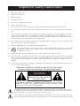
CAUTION
RISK OF ELECTRIC SHOCK
DO NOT OPEN
CAUTION: TO REDUCE THE RISK OF ELECTRICAL SHOCK, DO NOT
REMOVE COVER. NO USER-SERVICEABLE PARTS INSIDE. REFER
SERVICING TO QUALIFIED PERSONNEL.
WARNING: TO REDUCE THE RISK OF FIRE OR ELECTRIC SHOCK,
DO NOT EXPOSE THIS APPLIANCE TO RAIN OR MOISTURE.
e lightning ash with arrowhead symbol within an equilateral triangle is intended to alert the user
tothepresenceofuninsulated“dangerousvoltage“withintheproduct’senclosurethatmaybeofsuf-
cient magnitude to constitute a risk of electric shock to persons.
e exclamation point within an equilateral triangle is intended to alert the user to the presence of im-
portant operating and maintenance (servicing) instructions in the literature accompanying the product.

4
Contents
Welcome to the Classé family ..........................................................................5
a word about installation .......................................................................................5
Unpacking and Placement ............................................................................... 6
unpacking your amplifier ....................................................................................... 6
placement .............................................................................................................. 6
ventilation ..............................................................................................................6
custom installations ...............................................................................................6
rack-mounting ......................................................................................................7
serial number ......................................................................................................... 8
operating voltage ...................................................................................................8
warm up/break-in period .......................................................................................8
please read this manual… ......................................................................................8
Special Design Features ...................................................................................9
highly refined circuit design ...................................................................................9
extensive listening tests .......................................................................................... 9
extraordinary longevity ..........................................................................................9
robust protection ....................................................................................................9
Front Panel .....................................................................................................10
Rear Panel ...................................................................................................... 11
Installation .....................................................................................................16
Auto Standby .......................................................................................................17
Wake on LAN ......................................................................................................17
CAN-Bus ..............................................................................................................18
features ..............................................................................................................18
hardware setup ..................................................................................................18
using CAN-Bus.....................................................................................................20
CAN-Bus shared features ....................................................................................20
configuration........................................................................................................20
operate .................................................................................................................20
AC status ..............................................................................................................21
status ....................................................................................................................21
name ....................................................................................................................21
global brightness .................................................................................................. 21
global standby ................................................................................. 21
CAN-Bus model- ..................................................................................................21
specific features ...................................................................................................21
PlayLink ........................................................................................... 21
amp info .......................................................................................... 22
event log .......................................................................................... 22
Care and Maintenance ................................................................................... 23
Troubleshooting .............................................................................................24
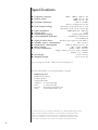
Specifications .................................................................................................26
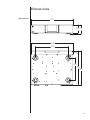
Dimensions .................................................................................................... 27

5
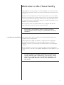
Welcome to the Classé family
Congratulations on your purchase of a Classé amplier. It is the result of many
years of design experience, and we are sure that you will enjoy it for many years
to come.
We value our relationship with our customers. Please allow us to stay in touch
with you by returning your warranty card now, before you pack up the shipping
carton of your new product and forget all about it. Doing so will enable us to
let you know about any possible future upgrades or updates that might become
available for your Classé component.
You can register online at www.classeaudio.com or complete and mail the
registration card located in the separate warranty booklet.
Please take a few moments now to register your new
Classé amplifier and record your serial number for future
reference
a word about installation EveryeorthasbeenmadetomaketheClasséSigmaMONOsimpleand
straightforward to install and use.
It may be placed on a shelf, in a cabinet or on the oor near the speaker(s).
AlthoughtheSigmaMONOisanextremelyecientdesign,aswithall
ampliers, some heat is generated and care should be taken to allow adequate
ventilation.
e size and shape of your room, its acoustics, and the associated equipment
you have chosen to use with your amplier all inuence the performance of your
system.
For this reason, we strongly encourage you to have your
system installed and calibrated by your dealer, whose
experience, training, and specialized equipment can
make a profound difference in the final performance of
the system.

6
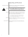
Unpacking and Placement
unpacking your amplifier Carefully unpack your power amplier according to the supplied instructions,
and remove all accessories from the carton. Please take care when lifting the
amplier, as it is heavier than it may appear.
Important! Keep all packing materials for future transport of your
Classé amplifier. Shipping your new component in
anything other than its purpose-designed packing material
may result in damage that is not covered by the warranty.
placement Many installations will utilize an equipment rack, although a shelf, a cabinet or
the oor near the speaker(s) are acceptable alternatives. In any case, take care to
position it well away from source components and preamp/processors, which
maybesensitivetotheamplier’selectromagneticelds.
Note that adequate clearance for the AC cord and connecting cables
must be left behind the amplier. We suggest leaving six inches (15 cm)
of free space behind your power amplier to allow all cables sucient
room to bend without crimping or undue strain.
ventilation Your Classé power amplier generates a certain amount of heat in the course of
normal operation. Avoid placement on soft surfaces that would restrict airow
around the unit (such as plush carpeting).
custom installations Drawings are included in this manual to facilitate special installations and
custom cabinetry (see the section Dimensions). Contact your Classé dealer for
more information.

7
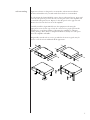
rack-mounting
Sigma series chassis are designed to accommodate rack-mount installation.
Professional installation by an authorized Classé dealer is recommended.
TorackmounttheSigmaMONO,removethetwoside-panelscrews,invertand
rotate the side panel to position the rack ear along the front of the amplier and
re-install the side-panel screws. Repeat for the side panel on the opposite side.
Remove the feet from the bottom of the amplier.
CarefullyinstalltheSigmaMONOintotheequipmentrackusingthe
appropriate screws for the type of rack. It is easiest if two people perform the
installation to avoid the possibility of dropping the amplier or otherwise
causing damage. Please allow for adequate ventilation, usually two rack spaces
above the amplier will suce.
Magnetically secured rack ear covers, provided in the accessory pack, may be
used to cover the screws and nish o the appearance.

8
serial number e serial number for your power amplier is found on the rear of the unit.
Please note and record this number on the page entitled Important Safety
Instructions for your future reference.
operating voltage eoperatingvoltageofyourSigmaMONOis100-240V,50/60Hz.
Warning: There are no user-serviceable parts within the unit. Please
refer any problems to an authorized Classé service center.
e amplier can easily be powered by a normal 15 or 20-ampere AC mains
line. If other devices are also powered from the same AC line, their additional
power consumption should be taken into account.
warm up/break-in period Your new Classé power amplier will deliver outstanding performance
immediately. However, you should expect to hear it improve somewhat as
it reaches its normal operating temperatures and its various components
“break-in.” It has been our experience that the greatest changes occur within the
rst 72 hours, as the amplier reaches thermal equilibrium and the capacitors
fully form. After this initial break-in period, the performance of your new
amplier should remain quite consistent for years to come.
please read this manual… Please take a few minutes to review this manual, and to familiarize yourself with
your new amplier. We understand that you are anxious to plug everything in
and get started. However, reading this manual and following the advice it gives
will ensure that you get all the benets you deserve from having purchased such
a ne piece of equipment.

9
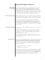
Special Design Features
highly refined
circuit design
is Classé amplier benets from the use of high quality component parts,
application of advanced class D amplier design principles and exhaustive
testing.ToconqueroneofthemostchallengingproblemsinclassDdesign,a
dead-band time minimization algorithm is initiated at turn-on to ensure the
lowestpossibledistortion;consequently,lessoverallnegativefeedbackisrequired
for optimum performance. is unusual accomplishment showcases both the
innovation of the design and the persistence of the Classé Design team.
extensive listening tests Excellent measured performance is to be expected in world-class products, and
Classé products deliver that performance. However, experience has shown that
technical excellence alone is insucient to guarantee subjectively musical results.
For this reason, all Classé products are laboriously ne-tuned during the
development process by carefully controlled listening tests. Our ears are still
some of the nest test instruments available, and nicely complement more
traditional engineering test equipment. We rely on careful listening tests, which
we view as a necessary complement to the solid engineering you should rightly
expect from Classé.
extraordinary longevity e Classé Design team has accumulated vast experience in what works well over
the long term.
By using only the highest quality parts to begin with, and then using them in
an informed way as a result of both accelerated aging tests and actual long-
term experience, we are able to design and manufacture products which we are
condent will stand the test of time.
We are condent that your new Classé amplier will give you many years of
trouble-free reliability and musical enjoyment, just as previous Classé products
have given their owners.
robust protection Finally, your new Classé amplier incorporates a variety of protection circuits, all
designed to protect both the amplier and your loudspeakers against dangerous
fault conditions. Signicantly, these protection circuits do not intrude upon
orlimitthenormalperformanceoftheamplier;rather,theysimplyputthe
amplier into protection mode when confronted with abnormal conditions.
ese conditions include:
• outputoverloadandshortcircuitprotection
• DCoset
• excessiveoperatingtemperatures
Some conditions, such as DC oset, are corrected automatically in the amplier
while others will result in either the amplier temporarily reducing its output
or, in extreme cases, switching itself o. In such a case, the Standby LED status
indicator will blink red until the fault can be righted and the amplier is reset by
pressing and holding the standby button for at least three seconds.

10
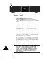
Front Panel
1 Standby/ON Button & Status Indicator LED
e front panel Standby button will toggle the amplier between
operate, its fully operational state, and a standby mode. (See also Wake on
Network).
e current state of the amplier is indicated by the LED status indicator
in the Standby button. e state of this LED indicates the following:
• on(red) = standby
• ashing(blue) = initialization
• on(blue) = operate
• slow ashing (red) = protection circuit(s) engaged
When in standby,theamplier’sgainstagesarepowereddown.Onlya
small power supply and control circuit remain on, consuming relatively
little power. Fortunately, since the output stages by their nature conduct a
great deal of current, they warm up and sound their best very quickly.
If you are not going to use the amplier for an extended period of time, we
suggest you disconnect it from the AC mains.
Also, it is a good practice to physically disconnect any and all valuable
electronics from the AC mains during electrical storms, as a lightning
strike anywhere near your home can put a tremendous surge on the AC
mains that can easily damage any piece of electronics, no matter how well
designed and protected. e best protection in the case of severe electrical
storms is to simply remove the electronics from any connection with the
power grid.
Caution! If you see the Standby LED indicator blinking red, please
check that all external connections are cleanly made
and secure. If no fault is immediately obvious, try to
reset the amplifier by pressing and holding the standby
button. If the unit does not reset or continues to enter
protection mode, please call your authorized Classé
dealer for assistance.
SIGMA MONO

11
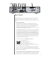
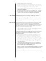
Rear Panel
e following descriptions are intended as a quick reference, should you have
any questions about your new product. Please see the next section (entitled
Initial Setup) for specic advice on incorporating your new amplier into your
system.
1 Balanced (XLR) Input
Balanced audio interconnections were originally developed for the
telephone and more recently have been used in the professional audio
world for preserving the delicate nuances of extremely small microphone-
level signals. For many years now, they have also been used by
performance-oriented companies such as Classé to preserve every nuance
of the nest audio recordings in your collection.
Technically,balancedaudiointerconnectionsprovidetwodistinctbenets:
theydoublethesignal’sstrengthasittravelsfromonecomponenttothe
next,increasingthepotentialSignal-to-Noiseratioby6dB;theyalsodo
an excellent job of rejecting noise and interference that might otherwise
be picked up between the components. If executed with a high degree of
symmetry between the inverting and non-inverting signal paths, balanced
connections can oer the best performance. For this reason, we strongly
recommend using the balanced analog interconnections between your
Classé components wherever possible.
e pin assignments of these XLR input connectors are:
Pin 1: Signal ground
Pin 2: Signal + (non-inverting)
Pin 3: Signal – (inverting)
Connector ground lug: chassis ground
ese pin assignments are consistent with the standard adopted by the
Audio Engineering Society (AES14-1992).
If you are using your Classé power amplier with a Classé preamplier/
processor,you’reallset–justremovethesuppliedshortingpin(between
Pins1and3)fromtheamplier’sXLRconnector,takeastandardbalanced
interconnect cable and plug it in.
If you are using another brand of preamplier or processor, please refer to its
operating manual to verify that the pin assignments of its output connectors
correspond to those of your amplier. If not, have your dealer obtain cables
with the appropriate output pin connecting to the equivalent input pin.
OUTPUT
IN OUTIN OUT
CAN BUSRS 232
UPDATE
HOST
CLASS 2 WIRING
INPUT
OUTPUT
IN OUT
100-120~ T6.3AH 250V
220-240~ T3.15AH 250V
CAUTION! TO REDUCE THE RISK OF ELECTRIC SHOCK, GROUNDING
OF THE CENTER PIN OF THIS PLUG MUST BE MAINTAINED
AVIS! POUR RÉDUIRE LE RISQUE DE CHOC ÉLECTRIQUE
LA FICHE CENTRALE DE LA PRISE DOIT ÊTRE
BRANCHÉE POUR MAINTENIR LA MISE À LA TERRE
RISQUE DE CHOC ÉLECTRIQUE-NE PAS OUVRIR
SHOCK HAZARD - DO NOT OPEN
THIS DEVICE COMPLIES WITH PART 15 OF THE FCC RULES.
OPERATION IS SUBJECT TO THE FOLLOWING TWO CONDITIONS:
(1) THIS DEVICE MAY NOT CAUSE HARMFUL INTERFERENCE, AND
(2) THIS DEVICE MUST ACCEPT ANY INTERFERENCE RECEIVED,
INCLUDING INTERFERENCE THAT MAY CAUSE UNDESIRED OPERATION.
1 4235 6 789 11 10

12
2 Single-Ended (RCA) Input
Single-ended cables using RCA connectors are the most common form
of analog connection used in consumer electronics. When implemented
carefully and with use of high quality interconnecting cables, this standard
can provide excellent performance. Classé has gone to extraordinary eort
to ensure that the single-ended (RCA) inputs of your power amplier
perform exceptionally well.
3 Balanced and Single-Ended Output
Balanced and single-ended output connectors allow the input signal to be
passed on to a second amplier for bi-amping or to an active subwoofer.
e single-ended output is converted from balanced (not just half of the
balanced signal) so the signal gain is the same should you choose to use the
balanced input and require the single-ended output for a subwoofer, for
example.eBalanced(XLR)connectorhasthesamewiringconvention
as described for the Input.
4 Speaker Outputs
Twopairsofhigh-qualityve-way binding posts are provided on the
amplier, in order to facilitate bi-wiring.
In practice, bi-wiring involves connecting two (preferably identical) sets
of speaker cables between each amplier channel and its corresponding
loudspeaker. In many cases, the benet is a subjectively improved level of
clarity and detail from the speaker, as a result of being able to feed the two
separate sections of its crossover and driver complement with identical, yet
separate signals.
(Many high quality loudspeakers also oer two sets of connections on their
speakers. Generally, one set of the connections on the loudspeaker feeds the
portion of the speaker’s crossover network that supplies the woofer with its
signal; the other set of connections connects to the portion of the crossover that
supplies the rest of the speaker with the midrange and high frequencies.)
Although the binding posts on your Classé amplier will accept bare wire
connections, we strongly recommend the use of high quality spade or hook
lugs, crimped onto the ends of your speaker wires. Using high quality
connectors will ensure that your speaker connections do not gradually
deteriorate from fraying and oxidizing bare wires. It also helps prevent
accidental short-circuits from poorly-terminated connections.
5 Classé CAN-Bus Control Ports
ese RJ-45 connectors are reserved for control and communication
applications using a Classé implementation of the Controller Area
Network(CAN)Busspecication.RefertotheCAN-Bus section located
later in this manual for more information.

13
6 IR Input and Output
Your Classé amplier includes two
1
/8
th
-inch mini mono-jacks in order to
support the IR remote controls that are ubiquitous today. IR commands
exist for toggling the amplier between operate and standby, as well as
discrete command codes for either operate or standby. ese codes may be
used in “macros” for sophisticated remote control systems, facilitating the
control of the amplier in the larger context of a complete system.
Actually, this IR Input and Output description is a bit of a misnomer: the
input supplied to these plugs is electrical in nature, not IR. It is obtained by
using standard IR receivers, distribution ampliers, and emitters (available
fromyourdealer)totranslatetheremote’sashesofinfraredlightinto
corresponding pulses of electricity. e big advantages here include being
able to easily route the signals anywhere they might need to go, and the
reliability of a solid electrical connection.
Since an IR distribution system such as your dealer may design for you
usually must control many products, your amplier includes both an IR
input (for the control of this product) and an IR output (so as to pass
along the same signal to the next product). is allows you to “daisy chain”
your control wires from one product to the next.
e amplier is designed to respond to IR commands of 5 Volts DC, with
the tip of the mini-plugs dened to be “positive” relative to the shank of
the plug.
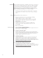
7 DC Trigger Input and Output
Many audio/video preampliers can supply a DC control voltage to
associated equipment in order to induce desired behavior. Your Classé
amplier can take advantage of these capabilities in order to be switched
between operate and standby automatically, perhaps in concert with the
preamp/processor itself.
Two
1
/8
th
-inch mini mono-jacks provide this remote-controlled turn-on
(that is, toggling between operate and standby) of the amplier. ese jacks
provide a simple pass-through of the control voltage from one to the other,
allowing you to “daisy-chain” a series of ampliers quite easily.
e remote trigger will be operated by the presence of 5–12 Volts DC,
with tip polarity as shown below:

14
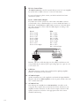
8 RS-232 Control Port
is RJ-45 connector is used for external RS-232 control of your amplier
bysystemssuchasAMX
®
, Crestron
™
,
Control 4
™
and Savant.
For more information, please contact your dealer and ask about home
automation systems.
RJ-45 - DB9 female adaptor
If your RS-232 control system uses a cable with a male DB9 connector,
you will need to buy or build an adaptor to convert the RJ-45 female to a
DB9 female. Standard RJ45-to-DB9 female connectors come with RJ-45
pins and connections as below. Wire the DB9 adaptor according to this
diagram and table.
RJ-45 DB9
Pin-1 = DSR Pin-1=N/C
Pin-2=DTR Pin-2=RXD
Pin-3=CTS Pin-3=TXD
Pin-4=GND Pin-4=DTR
Pin-5=RXD Pin-5=GND
Pin-6=TXD Pin-6=DSR
Pin-7=N/C Pin-7=N/C
Pin-8 = Power Input Pin-8=CTS
Pin-9 = Power Input
Remarks: e Cat 5 cable that plugs into this adaptor and then into the
rear panel RJ-45 port must use pin-to-pin wiring (pin one to pin one, two
to two and so on).
9 USB Port
e USB connector is used to host a USB stick for updating amplier
rmware, should that become necessary.
10 AC Mains Input
AnIECstandardpowercord(supplied)isusedwiththeSigmaMONO.
Plug the cord into the IEC receptacle on the rear panel, and the other end
into a suitable wall outlet.
11 AC Mains Fuse
Your Classé power amplier has an AC mains fuse, accessible on the
rear panel. If you suspect that your AC fuse has blown, disconnect your
amplier from the AC mains, as well as from its input connections and
speaker connections, and refer to the appropriate item of the section
enitled Troubleshooting.

15
Do not open your amplier. ere are no user-serviceable parts within
this product.
Danger! Potentially dangerous voltages and current capabilities
exist within your power amplifier, even when disconnected
from AC mains. Do not attempt to open any portion of the
amplifier’s cabinet. There are no user-serviceable parts
inside your power amplifier. All service of this product
must be referred to a qualified Classé dealer or distributor.

16
Installation
Your new Classé amplier is quite simple to set up and enjoy. Please follow the
steps outlined below in order to safely set up and use your new amplier.
Important:
The AC mains connection should be the last connection you
make on your new power amplifier. In addition, it is always
a good idea to power up your power amplifier(s) last, after
everything else has been powered up and has stabilized. .
Conversely, it is good practice to power the amplifier(s)
down first when shutting down the system, as this
prevents any transients from other components from
getting through to your loudspeakers.
1. Unpack everything according to the included instructions.
Be careful when doing so, as this amplier is heavier than it appears.
2.
Place your amplifier (be sure to read “Unpacking and Placement”)
and connect it to the AC mains. is includes deciding on the location,
making sure you have adequate ventilation, and adequate clearance for all the
wires behind the amplier. Once accomplished, connect the amplier directly to
the AC mains. Do not use extension cords, as most are not suitable for the current
sometimes required by your amplier.
3. Make your preamp/processor connections.
With the amplier in standby (or disconnected from the AC mains), using
a high quality interconnecting cable, make the appropriate connection
with the balanced or single-ended connector.
Make sure the connection is snug, even if it means gently squeezing
the outer shell of the RCA with pliers and reinserting it to tighten the
connection.
4. Make your speaker connections.
Make the connection between the output terminals of the amplier and
your loudspeakers, using high quality speaker wires.
Connect the black (–) terminal on the amplier to the black (–) terminal
on your speaker, and the red (+) terminal on the amplier to the red (+)
terminal on your speaker. If bi-wiring, run a total of four conductors
between each amplier channel and its corresponding loudspeaker: two
separate +/– leads, one for the bass and the other for the mids and treble.
Make sure that no wires cross between the red (+) and black (–) terminals,
at either end.
Make sure all the connections are snug and cannot be easily wiggled free,
but do not overtighten them. If you can give the speaker wires a reasonable
tug without movement, they are snug. Further tightening will not make a
better connection, and (taken to the extreme) may damage the connectors.

17
5. Double-check all your connections.
We understand that this step sounds redundant, but it is worth the extra
minute or two it might take just to ensure that all connections are correct
and secure before plugging the power cables to the AC outlets.
6. Turn on all the other components in your system, and then
turn on your amplifier.
It is always good practice to turn any power amplier on last, and to turn
it o rst. Doing so prevents any turn-on/turn-o transients that might
originate in other components from damaging your loudspeakers.
Auto Standby eMONOemployspowersavingfeaturestoensurethatitconsumesa
minimal amount of power while not in use. Auto Standby will switch the
amplier o if no audio signal is present for approximately 15 minutes (and
ifaDCtriggerisn’toverridingit).edefaultmodeisfortheAutoStandby
feature to be enabled. If for some reason this feature must be disabled, see the
instructions below.
Wake on LAN eSigmaMONOsupportsnetwork-enabledcontrolusingRS-232orCAN
Bus interfaces. A low power standby mode may be engaged by disabling
somethingcalledWakeonLANmode.*WithWakeonLANdisabled,RS-232
andCANBuscontrolwillnotbeabletowaketheamplierfromstandbyso
DC trigger or front panel commands are required.
*Note that UKEC version units such as those sold in the European Union are
shipped with Wake on LAN mode disabled.
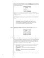
To identify whether the Auto Standby and Wake on LAN features
are enabled or disabled and to change their state(s), use the
following procedure:
1. While holding the Standby button depressed, plug in the power cord.
2. e amplier will enter a Conguration mode where the behavior of
the LED indicates whether each feature is enabled (solid) or disabled
(ashing). e status of Auto Standby is indicated by the behavior of the
LEDwhileGreenandthestatusoftheWakeonLANfeatureisindicated
by the behavior of the LED while Amber. e LED will toggle between
Green(AutoStandby)andAmber(WakeonLAN)toalternatelyshowthe
status of these features.
3.Tochangethestatusofeitherfeature,waituntilitscolorisdisplayed
by the LED, then press the Standby button. is will toggle the feature
between enabled (solid) and disabled (ashing) states.
Example: An amplier with Auto Standby disabled and Wake on LAN enabled
would alternately show a ashing Green and solid Amber LED while in the
Conguration mode.
4.Toreturntonormaloperation,disconnectandreconnectthepowercord.

18
CAN-Bus Classé’sControllerAreaNetwork,orCAN-Bus,opensthewaytoanewlevelof
interaction between similarly featured Classé
components. When the amplier
isconnectedwithotherCAN-Bus-equippedClass
é
components, the dierent
elements in the system are in constant communication, creating a “global”
network that delivers system wide status information and shared operational
features,allthroughthepreamp/processor’stouchscreendisplay.
Note that some components will require a software update to recognize the
Sigma MONO on the CAN-Bus. Check the Classé website periodically for
updates.
features CAN-Buswillallowa
Class
é touchscreen to:
• Displaystatusinformationforeveryconnectedunit,including
ampliers which do not have a touchscreen display.
• Createa“PlayLink”thatallowsanSSPorPreamptoautomatically
switch to the correct input when a Delta series source component
starts playback.
• Adjusttheglobalsystembrightness.
• Conguretheentiresystemtogoinandoutofstandbyatthe
touch of a button and also bring individual components in and
out of standby.
• Muteanyconnectedunit.
hardware setup 1 Classé CAN-Bus Equipped Products
TwoormoreClasséCAN-Busequippedproductsarerequired,atleastoneof
which must have a touchscreen display.
2 Category 5 Network Cables
ese are ordinary network cables, commonly used for broadband Internet
connections. ey should be typical “straight through” cables not the “crossed
over” type, and the total required will be one less than the total number of
CAN-Busequippedcomponentsinyoursystem.
3 CAN-Bus Terminator
AsingleCAN-BusTerminatormayberequired.Itisinsertedintothe
CAN-BusOUTconnectorofthelastcomponentintheCAN-Bus
daisy chain. One is
includedintheboxwithyouramplier.T
hey are also
available free of charge from your nearest Classé Customer Support Centre.
http://www.Classeaudio.com/support/service.htm
4 SSP-300 & 600 CAN-Bus Interface Box
Systems that include an SSP-600 or SSP-300 will also require an
SSP-300/600CAN-BusInterfaceBox.eseareincludedwiththeproductsor
available free of charge
from your nearest Classé Customer Support Centre.
http://www.Classeaudio.com/support/service.htm

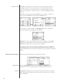
19
ediagramsbelowillustratehowtoconnecttheCAN-Bushardware.
Any combination of models in any order.
OUT
CAN-BUS
IN
OUT
CAN-BUS
IN
OUT
CAN-BUS
IN
OUT
CAN-BUS
IN
For any system with SSP-300 or SSP-600.
OUT
CAN-BUS
IN
OUT
CAN-BUS
IN
OUT
CAN-BUS
IN
OUT
CAN-BUS
IN
NOTE:DaisychainmayneedtobeterminatedwithCAN-BusTerminator.

20
using CAN-Bus CAN-Busiscontrolledviathetouchscreenofany
Classé
component that is
so equipped. ere is no master component, so
Classé
series systems where
two or more units have a touchscreen can be controlled through any of the
touchscreens.However,itisprobablyeasiesttostartusingCAN-Busthrough
just one.
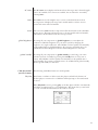
CAN-Busisaccessedbypressingthemenu button on the face of the unit or
remote, then the status button, followed by the more button.
e touchscreen will then display the CAN-Bus devices screen, which lists
connected components by model & serial number.
Highlighting aunitontheCAN-Busdevicesscreenidentiesitasthetarget
unit. e front panel LEDs of the target unit will start ashing (unless you
highlighttheunitthatyouareusingtoaccessCAN-Bus).
Once you have chosen the target unit press select.etargetunit’sLEDswill
stopashingandthetouchscreenwilllisttheCAN-Busfeaturesavailabletoit.
SomeCAN-Busfeaturesaresharedbyallmodels,somearespecictoindividual
models.
CAN-Bus shared features efollowingCAN-Busfeaturesaresharedbyallmodels.
configuration Selecting conguration will present the CAN-Bus conguration screen
allowing access to name, global brightness, and global standby features.
operate e operate settings allow you to bring the target unit in and out of standby, or
mute. is key will be disabled for the unit whose touchscreen you are using to
accessCAN-Bus.
Page is loading ...
Page is loading ...
Page is loading ...
Page is loading ...
Page is loading ...
Page is loading ...
Page is loading ...
Page is loading ...
-
 1
1
-
 2
2
-
 3
3
-
 4
4
-
 5
5
-
 6
6
-
 7
7
-
 8
8
-
 9
9
-
 10
10
-
 11
11
-
 12
12
-
 13
13
-
 14
14
-
 15
15
-
 16
16
-
 17
17
-
 18
18
-
 19
19
-
 20
20
-
 21
21
-
 22
22
-
 23
23
-
 24
24
-
 25
25
-
 26
26
-
 27
27
-
 28
28


Classé Sigma MONO Owner's manual
- Category
- Supplementary music equipment
- Type
- Owner's manual
Ask a question and I''ll find the answer in the document
Finding information in a document is now easier with AI
Related papers
-
Classé Sigma AMP2 Owner's manual
-
-
Classe Audio CA/CT-2300 User manual
-
Classe Audio SSP-800 Owner's manual
-
Classe Audio CA-3200 Owner's manual
-
-
-
Classe Audio CA-2100 User manual
-
-
Classe Audio CA-M300 - V1.4 Owner's manual
Other documents
-
 StarTech.com C9PCF Datasheet
-
-
Classe Audio CAP-2100 User manual
-
-
-
-
-
-
-
