2. Place one of the phillips pan head screws into
one of the recessed holes in the blade bracket.
Turn screw until it mates with threaded hole in
hub. Do not tighten screw completely at this time.
(Figure 6)
3. Install the second
screw in the same
manner, then
tighten both screws
firmly.
4. Install the remaining
blade assemblies by
repeating the above
steps.
42" HUGGER CEILING FAN
NOTE: The blades should be attached to the fan after
it is hung and wired to prevent blade brackets from
being bent and causing the fan to wobble.
BLADE ASSEMBLY AND ATTACHMENT
INSTRUCTION MANUAL
Model 9842
MAINTENANCE
Periodic cleaning of your ceiling fan is the only
maintenance that is needed. When cleaning, use only
a soft brush or lint free cloth to avoid scratching the
finish. Abrasive cleaning agents are not required and
should be avoided to prevent damage to the finish.
Do not spray water directly onto your ceiling fan. It
could damage the motor or the blades and create
the possibility of an electrical shock or fire.
WARRANTY
The ceiling fan you have purchased is warranted by
the manufacturer for one year from the date of
purchase against defects in workmanship and/or
materials. The motor is warranted for ten years. This
warranty means that only the parts that prove to be
defective during the period of warranty will be either
repaired or replaced at our option. The right is reserved
by the manufacturer to replace the whole product in
lieu thereof. Should repair become necessary during
the warranty period, write to: AIR KING c/o LASKO
PRODUCTS, INC., Appliance Service Department, 820
Lincoln Ave., West Chester, PA 19380. Describe the
problem you are having. DO NOT SEND FAN!
This warranty does not apply if the damage occurs
because of accident, improper handling, installation
or operation, shipping damage, abuse, misuse or
unauthorized repairs made or attempted. ALL
WARRANTIES, EXPRESSED OR IMPLIED LAST FOR ONE
YEAR FROM DATE OF ORIGINAL PURCHASE, EXCEPT
FOR THE MOTOR. THIS WARRANTY DOES NOT COVER
LIABILITY FOR INCIDENTAL OR CONSEQUENTIAL
DAMAGES FOR ANY CAUSE WHATSOEVER. Some states
do not allow limitations on how long any implied
warranty lasts, or the exclusion or limitations of
incidental or consequential damages, so that the above
limitation or exclusion may not apply to you. This
warranty gives you specific legal rights, and you may
have other rights that vary from state to state.
FOR REPLACEMENT PARTS: Please call 1-800-966-2028,
Monday - Friday, between the hours of 8am and 4 pm
EST. Reference the type and style of product when
you call.
FOR QUESTIONS OR COMMENTS ABOUT YOUR
CEILING FAN: Please call 1-800-233-0268, Monday -
Friday, between the hours of 8am and 4pm EST.
New 8/00
Your new ceiling fan will require a grounded electrical
supply line of 120 volts AC, 60 Hz, 15 amp circuit. The
42" total fan weight is 10 lbs maximum.
WARNING: To reduce the risk of fire, electrical shock
or personal injury, mount fan at least 7 feet above
the floor to an outlet box marked “Acceptable for
fan support.” Use screws provided with outlet box.
Most outlet boxes commonly used for the support
of lighting fixtures are not acceptable for fan support
and may need to be replaced. Consult a qualified
electrician if in doubt.
Your ceiling fan will fit any of the following electrical
boxes: 4" octagon box, 3" octagon box, 1/2" deep
ceiling pan, or a plaster ring with 3 1/2" mounting
hole centers mounted on one of the above listed
boxes. Your new fan will also install on a “wiremold”
No. 5738 fixture box. The electrical box must be
securely anchored an capable of withstanding a load
of at least 50 pounds.
If your ceiling fan does not have one of the above
electrical boxes for proper wiring, you may wish to
contact a licensed electrician for installation.
READ AND SAVE THESE INSTRUCTIONS
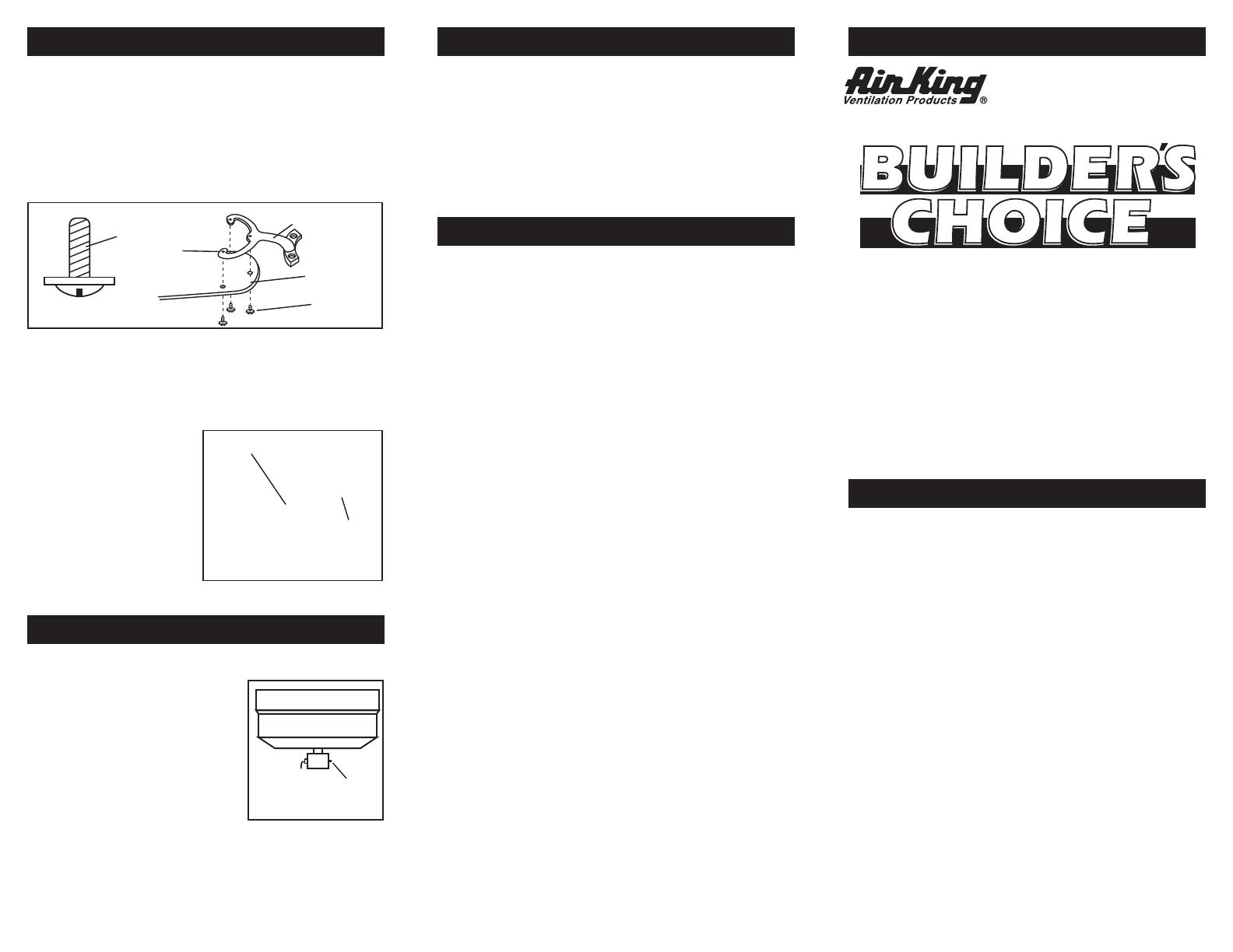
1. Using three phillips washer head screws, secure
one bracket to each of the blades. Complete this
assembly before attaching blades to ceiling fan.
(Figure 5)
Figure 5
Phillips Washer
Head Screw
Blade Bracket
Blade
Screws
Figure 6
Motor Hub
Blade
Bracket
Phillips Pan
Head Screw
USING YOUR CEILING FAN
1. Restore power to the electrical box.
2. Check the operation of the
fan by gently pulling the
chain switch.
3. To reverse airflow direction,
turn fan off and wait for
the blades to come to a full
stop, then slide reversing
switch to opposite position.
(Figure 7)
4. Your ceiling fan is equipped with four position,
three speed pull chain switch.
Figure 7
Reversing Switch


