RTI PCM-4 Quick Reference Manual

Type
Quick Reference Manual

RTI PCM-4 is a port control module that expands the I/O capabilities of an RTI XP series control processor, providing increased flexibility for larger projects. It features four multi-purpose I/O ports with IR output and routing, one-way RS-232 communication, and power sensing. The Ethernet port allows for control and updating over the LAN, and the module supports an unlimited number of PCM-4 units in one system.

RTI PCM-4 is a port control module that expands the I/O capabilities of an RTI XP series control processor, providing increased flexibility for larger projects. It features four multi-purpose I/O ports with IR output and routing, one-way RS-232 communication, and power sensing. The Ethernet port allows for control and updating over the LAN, and the module supports an unlimited number of PCM-4 units in one system.

70-210127-20 V1.0
Quick Reference Guide
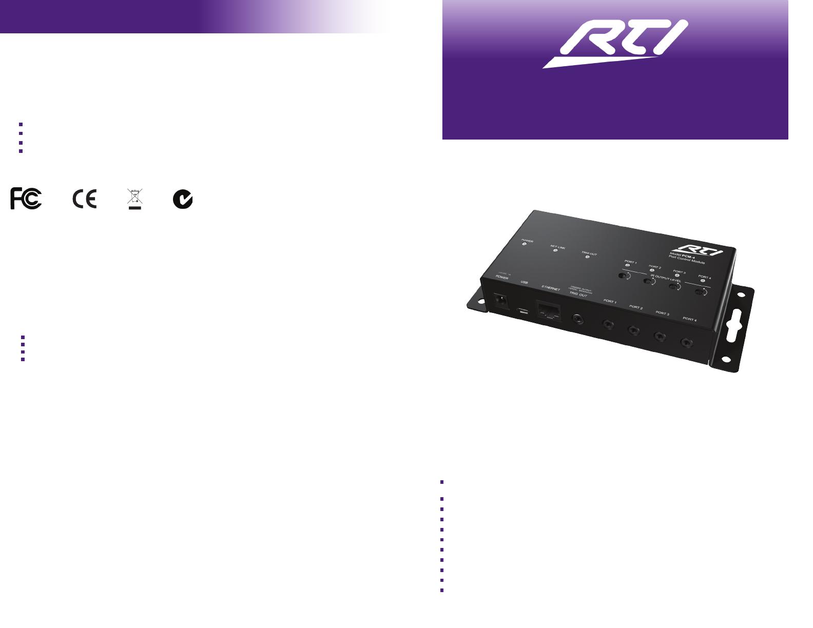
Port Control Module
PCM-4
It’s Under Control
®
With four multi-purpose I/O ports and a voltage trigger output, the PCM-4 provides the exibility to
increase the I/O capabilities of an RTI XP series control processor to accommodate larger projects.
Each MPIO port provides IR output and routing capabilities, one-way RS-232 communication (with
CM-232) and power sensing (with RTI accessory devices). Control from the XP series control
processor is communicated using the LAN (Ethernet - Local Area Network). This allows the MPIO
ports of the PCM-4 to become a seamless extension of the processor’s existing ports.
The PCM-4 provides superior quality and reliability as well as these specic features:
Expands I/O port capabilities of an RTI XP series control processor (IR, one-way RS-232,
sensing).
Ethernet port provides control and updating over the LAN (Local Area Network).
Virtually unlimited number of PCM-4 units in one system.
I/O ports are compatible with industry standard IR emitters, blasters, and repeater systems.
Variable IR output on all ports.
LED illuminates when ports are active.
I/O ports support all optional RTI power sensing and communications modules.
One 12VDC/100mA voltage trigger output.
Powered using included power supply or PoE (Power over Ethernet).
USB port for on-site rmware updates.
Sturdy steel construction.
Safety Suggestions
Read and Follow Instructions. Read all safety and operating instructions before operating the unit.
Retain Instructions. Keep the safety and operating instructions for future reference.
Heed Warnings. Adhere to all warnings on the unit and in the operating instructions.
Heat. Keep the unit away from heat sources such as radiators, heat registers, stoves, etc., including ampliers that produce
heat.
Power Sources. Use only batteries of the type described in the operating instructions, or as marked on the unit.
Water and Moisture. Do not use the unit near water—for example, near a sink, in a wet basement, near a swimming pool,
near an open window, etc.
Object and Liquid Entry. Do not allow objects to fall or liquids to be spilled into the enclosure through openings.
Servicing. Do not attempt any service beyond that described in the operating instructions. Refer all other service needs to
qualied service personnel.
Damage Requiring Service. The unit should be serviced by qualied service personnel when:
Objects have fallen or liquid has been spilled into the unit.
The unit has been exposed to rain.
The unit does not appear to operate normally or exhibits a marked change in performance.
The unit has been dropped or the enclosure has been damaged.
Limited Warranty
RTI warrants its products for a period of one (1) year (90 days only for included battery packs); or for a period of time
compliant with local laws when applicable from the date of purchase from RTI or an authorized RTI distributor.
This warranty may be enforced by the original purchaser and subsequent owners during the warranty period, so long as the
original dated sales receipt or other proof of warranty coverage is presented when warranty service is required.
Except as specied below, this warranty covers all defects in material and workmanship in this product. The following are
not covered by the warranty:
Damage resulting from:
1. Accident, misuse, abuse, or neglect.
2. Failure to follow instructions contained in this Guide.
3. Repair or attempted repair by anyone other than Remote Technologies Incorporated.
4. Failure to perform recommended periodic maintenance.
5. Causes other than product defects, including lack of skill, competence or experience of user.
6. Shipment of this product (claims must be made to the carrier).
7. Being altered or which the serial number has been defaced, modied or removed.
This equipment has been tested and found to comply with the limits for a Class B digital device, pursuant to Part 15 of
the FCC Rules. These limits are designed to provide reasonable protection against harmful interference in a residential
installation. Any changes or modications not expressly approved by the party responsible for compliance could void the
user’s authority to operate the device.
This equipment generates, uses, and can radiate radio frequency energy and, if not installed and used in accordance with
the instructions, may cause harmful interference to radio communications. However, there is no guarantee that interference
will not occur in a particular installation.
If this equipment does cause harmful interference to radio or television reception, which can be determined by turning the
equipment off and on, the user is encouraged to try to correct the interference by one or more of the following measures:
Reorient or relocate the receiving antenna.
Increase the separation between the equipment and the receiver.
Connect the equipment into an outlet on a circuit different from that to which the receiver is connected.
Consult the dealer or an experienced radio/TV technician for help.
This device complies with Part 15 of the FCC Rules. Operation is subject to the following two conditions:
1. This device may not cause harmful interference.
2. This device must accept any interference received including interference that may cause undesired operation.
DECLARATION OF CONFORMITY (DOC)
The Declaration of Conformity for this product can be found on the RTI website at: www.rticorp.com/declaration
Federal Communications Commission Notice
N27917
If you are encountering any problems or have a question about your RTI
product, please contact RTI Technical Support for assistance (see the
Contacting RTI section of this guide for contact details).
RTI provides technical support by telephone or e-mail. For the highest quality
service, please have the following information ready, or provide it in your
e-mail.
Your Name
Company Name
Telephone Number
E-mail Address
Product model and serial number (if applicable)
If you are having a problem with hardware, please note the equipment in
your system, a description of the problem, and any troubleshooting you have
already tried.
Please do not return products to RTI without a return authorization.
Service & Support
For news about the latest updates,
new product information, and new
accessories, please visit our web site at:
www.rticorp.com
For general information, contact RTI at:
Remote Technologies Incorporated
5775 12th Ave. E Suite 180
Shakopee, MN 55379
Tel. (952) 253-3100
Fax (952) 253-3131
Contacting RTI
Copyright © 2013 • Remote Technologies Incorporated • All rights reserved.
Key Features
Installation & Operation
Connection Options
It’s Under Control
®
MOUNTING
The PCM-4 can be located on a secure, at surface or mounted horizontally or vertically using the
mounting slots or four mounting holes at the corners of the enclosure or on either end of the PCM-4.
POWERING THE PCM-4
1) AC Adapter: Connect the included power supply (12VDC/1Amp) to the power jack on the PCM-4.
or
2) Ethernet Port (Power over Ethernet): Connect a Cat-5 cable to a PoE compatible router/switch or a
PoE injector.
NOTE: The PCM-4 CANNOT be powered directly from an RTI control processor or connecting block.
USB PORT - UPDATING FIRMWARE
The PCM-4 rmware is updated via the integrated USB port using a USB-A to Micro-B cable (included).
Check the RTI website to see if there is a new rmware for the PCM-4 at www.rticorp.com/dealers.
ETHERNET NETWORK CONNECTION
The PCM-4 Ethernet port provides communication with a 10/100 Base-T Ethernet network (LAN) for
control via an RTI XP series control processor. The port is compatible with Cat-5 cable with an RJ-45
termination (568B). The NET LINK light located on the top of the PCM-4 will be lit red when connected to
the LAN and ashes when there is network activity.
1) Connect to the Ethernet network - Connect a Cat-5 cable to the Ethernet network (LAN) and the
PCM-4 will receive an IP address from the network router via DHCP.
2) Find the MAC address of the PCM-4 - Located on the unit and on the MAC address card in the box.
3) In Integration Designer, click on the XP processor and add the PCM-4 as an expansion device.
4) Enter the MAC address of the PCM-4 into the conguration elds. This will allow the RTI system to
locate the PCM-4 on the network.
NOTE: Setting a static IP address is unnecessary and not recommended. However, you can change IP
address settings in Integration Designer and download this information into the PCM-4 via the USB port.
PROGRAMMING THE PCM-4
The system conguration that is created in Integration Designer is downloaded into the PCM-4 across the
Ethernet network automatically. No direct programming of the PCM-4 is required unless the IP address
conguration is adjusted (see NOTE above).
NOTE: The port LEDs will continuously cycle until communication has been established with an XP series
control processor, at which point they blink twice and stop. Port LEDs then indicate IR/RS-232 activity.
MPIO PORTS - CONNECTING IR EMITTERS
The multi-purpose I/O ports on the PCM-4 are compatible with industry standard infrared emitters. Each
output port is capable of driving up to four infrared emitters directly. The use of more than four infrared
emitters requires the addition of an amplied connecting block. A connecting block can be wired up to
1000 feet away from the PCM-4 using #22 AWG (minimum) wire.
Adjusting IR Output Gain
The IR output gain can be separately adjusted for each of the four output ports. If adjustment is needed,
rotate the IR output controls on the top of the PCM-4 clockwise for higher output power, or counter-
clockwise for lower output power.
MPIO PORTS - CONNECTING POWER SENSOR MODULES (VPS-1)
The multi-purpose I/O ports on the PCM-4 are compatible with RTI power sensing modules (e.g. VPS-1).
Follow the guide included with the modules for installation instructions.
MPIO PORTS - CONNECTING RS-232 COMMUNICATION MODULES (CM-232)
The multi-purpose I/O ports on the PCM-4 are compatible with RTI communication modules (e.g. CM-
232) for one-way RS-232 communication. Follow the guide included with the module for installation
instructions.
VOLTAGE TRIGGER OUTPUT
The TRIG OUT jack (3.5mm mono plug) allows the PCM-4 to deliver a 12VDC/100mA voltage trigger to
devices. The TRIG OUT LED will light when voltage is sent.
RESET
ETHERNET
EXPANSION
PORT 1 PORT 2 PORT 3
PORT 4
PORT 5
PORT 6
+
+ +
+ +
+
USB
RTI COM
POWER
STATUS
RS-232
POWER / IR
+12VDC TRIGGER
+3-24VDC SENSE
RELAYS (+30VDC, 5A MAX)
IR OUTPUT LEVEL
1
2
Model XP-6
Advanced Control Processor
RTI XP-6
Silkscreen Graphics
May 27, 2010
Scale 1:1
Dimensions:
W: 6.8 Inches (173 mm) (Including wings)
H: 2.9 Inches (74 mm)
H: 1.2 Inches (31mm)
The following diagram shows one of the congurations that can be used with the PCM-4.
ZM-24 Transceiver Module
Power
Supply
PCM-4 Port Control Module
Product Contents
Contents within the box include the following items:
One (1) PCM-4 Port Control Module
One (1) 12VDC/1A power supply
One (1) USB cable: USB-A to Micro-B
One (1) Quick reference guide
One (1) Card with Ethernet MAC address and serial number
PCM-4
Port Control Module
Each IR output can drive up to
four emitters directly. More than
four emitters require an amplied
connecting block.
Direct to IR Port
Single or Dual
IR Emitters
CM-232 Communication Module
(RS-232 One-way)
Voltage From
Power Supply
IR Emitter
Equipment with switched outlet
or voltage trigger output
IR Connecting Block
Network Hub/Switch
RTI Remote Control
XP-6 Control Processor
Power
Supply
MPIO Connection Options
Tip = 12 VDC (+)
Ring = Ground (-)
Voltage Trigger Output
Outputs 12VDC/100mA
Uses 3.5mm Mono Plug
To device being triggered.
Ex. TV lift, Screen, Drapes etc.
  • Page 1 1
  • Page 2 2

RTI PCM-4 Quick Reference Manual

Type
Quick Reference Manual

RTI PCM-4 is a port control module that expands the I/O capabilities of an RTI XP series control processor, providing increased flexibility for larger projects. It features four multi-purpose I/O ports with IR output and routing, one-way RS-232 communication, and power sensing. The Ethernet port allows for control and updating over the LAN, and the module supports an unlimited number of PCM-4 units in one system.

Ask a question and I''ll find the answer in the document

Finding information in a document is now easier with AI