Page is loading ...

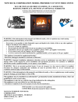
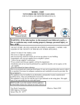
MODEL 34
MAY BE INSTALLED INA SOLID FUELBURNING FIREPLACE, AS A ZERO
CLEARANCE FIREPLACE OR WITH AN OPTIONAL SURROUND.
WARNING: If the information in this manual is not followed exactly, a fire or
explosion may result causing property damage, personal injury or loss of life.
Do not store or use gasoline or other flammable vapors and liquids in vicinity of this or any
other appliance.
WHAT TO DO IF YOU SMELL GAS:
Do not try to light any appliance.
Do not touch any electrical switch; do not use any phone in your building.
Immediately call your gas supplier from a neighbor’s phone. Follow gas supplier’s instruc-
tions.
If you cannot reach your gas supplier, call fire department.
Installation and service must be performed by a qualified installer, service agency or gas
supplier.
This is an unvented gas-fired heater. It uses air (oxygen) from room in which it is installed.
Provisions for adequate combustion and ventilation air must be provided. Refer to section “
Producing Adequate Air For Combustion And Ventilation” page 35.
This appliance may be installed in an aftermarket, permanently located, manufactured (mobile)
home, where not prohibited by local codes.
This appliance is only for use with type of gas indicated on rating plate. This appliance is not
convertible for use with other gases.
INSTALLER: Leave this manual with appliance.
CONSUMER: Retain this manual for future reference.
MANUFACTURED BY:
NEW BUCK CORPORATION
200 ETHAN ALLEN DRIVE
PO BOX 69
SPRUCE PINE, N.C. 28777
www.buckstove.com
This appliance is intended for supplemental heating.
Revised January 2013


TABLE OF CONTENTS MODEL 34
SECTION I: Safety Information.................................................................................................... 3
SECTION II: Fireplace Preparation/Solid Fuel Burning Fireplace (FP)....................................... 6
Fireplace Clearances(FP)................................................................................................................ 7
Gas Connection............................................................................................................................... 7
Placement of Logs........................................................................................................................8-9
Gas Pressure Check....................................................................................................................... 10
Lighting Instructions - ITT Millivolt Valve.................................................................................. 11
Lighting Instructions - SIT Modulating Valve or- Manual (SIT)................................................. 15
Lighting Instructions - SIT Millivolt Valve.................................................................................. 19
Flame Check.................................................................................................................................. 23
Heat Output................................................................................................................................... 23
Wiring Diagram ............................................................................................................................ 24
SECTION III: Solid Fuel Burning Fireplace Installation (FP)..................................................... 26
SECTION IV: Wooden Surround Installation (WS) ................................................................... 28
SECTION V: Zero Clearance (ZC).............................................................................................. 30
SECTION VI: Installation-After Market Mobile Home.............................................................. 34
SECTION VII: Producing Adequate Air For Combustion And Ventilation............................... 35
Air For Combustion And Ventilation Inside Building.................................................................. 37
Air For Combustion And Ventilation Outdoors............................................................................ 38
Important Safeguards.................................................................................................................... 39
Cleaning ........................................................................................................................................ 39
Trouble Shooting........................................................................................................................... 40
Service and Repair Parts ............................................................................................................... 44
Replacement Parts......................................................................................................................... 45
Warranty/Owner Registration....................................................................................................... 53


Page 3
SECTION I
SAFETY INFORMATION WARNINGS
IMPORTANT: READ THIS OWNER’S MANUAL CAREFULLY AND COMPLETELY
BEFORE TRYING TO ASSEMBLE, OPERATE, OR SERVICE APPLIANCE. IMPROPER
USE OF THESE LOGS CAN CAUSE SERIOUS INJURY OR DEATH FROM BURNS, FIRE,
EXPLOSION AND CARBON MONOXIDE POISONING.
NOTE: When burning any unit or appliance that combusts fuel for heat, such as
coal, oil, wood or natural and (L.P.) liquid petroleum gas, we highly recommend
use of smoke and carbon monoxide detectors in your home.
Early signs of carbon monoxide poisoning resemble flu, with headaches, dizziness and/or
nausea. If you have these signs, heater may not be working properly. Get fresh air at once!
Have heater serviced.
Some people-pregnant women, persons with heart or lung disease, anemia, those under
influence of alcohol and those at high altitudes-are more affected by carbon monoxide than
others.
CAUTION: Strong drafts, such as a ceiling fan placed directly in front of heater
(pulling from either direction) may create sooting. Sooting will discolor
walls.
1. The installation must conform with local codes or in the absence of local codes, with
National Fuel Gas Code, ANSI Z223.1/NFPA54.
2. This appliance may be installed in an After-Market
*
Manufactured (Mobile) Home,
where not prohibited by state or local codes.
*
(After-Market: Completion of sale, not for purpose of resale from manufacturer.)
This appliance is only for use with the type of gas indicated on rating plate.
This appliance is not convertible for use with other gases.
NOTE:
See Section VII, “Producing Adequate Air For Combustion And Ventilation” page 35.
IMPORTANT: VENT-FREE HEATERS ADD MOISTURE TO AIR. ALTHOUGH THIS IS
BENEFICIAL, INSTALLING HEATER IN ROOMS WITHOUT ADEQUATE
VENTILATION MAY CAUSE MILDEW TO FORM FROM TOO MUCH MOISTURE.
3. Never install this heater:
In a recreational vehicle, bathroom, bedroom or any other sleeping quarters.
Where curtains, furniture, clothing or other flammable objects are less than 42" from
front of heater
In high traffic areas or in windy areas
4. Two models are available. One specific model for propane (LP) and one for natural gas.
Use the correct type gas for your home. Do not convert from one gas type to another.
NOTE: This appliance complies with ANSI Z21.11.2b-2010 Unvented Room Heater.
WARNING: “ANY CHANGE TO THIS HEATER OR ITS CONTROLS CAN BE
DANGEROUS.”

Page 4
5. If this heater is used with propane gas, do not place propane supply tank(s) inside any structure.
6. What To Do IF You Smell Gas:
Shut off gas supply.
- Do not try to light any appliance.
- Do not touch any electrical switch; do not use any phone in your building.
- Immediately call your gas supplier from a neighbor’s phone. Follow gas supplier’s instructions.
- If you cannot reach your gas supplier, call fire department.
7. When operated for first time, logs may emit a “paper burning” smell. This smell will gradually
diminish and will be totally eliminated after first few hours of operation. Run gas logs with flue
damper open during this time. Do not use blower at this time.
8. “This heater shall not be installed in unusually tight construction unless provisions are
provided for adequate combustion and ventilation air.” See “Producing Adequate Air For
Combustion And Ventilation”, page 35.
9. Surface of gas logs becomes very hot when operating. Keep children and adults away from hot
surface. Gas logs will remain hot for sometime after shutdown. Allow surface to cool before
touching.
10. Do not place clothing or other flammable material on or near appliance.
11. If equipped, fresh air damper must be closed.
12. Keep appliance area clean and free from combustible materials, gasoline and other flamma-
ble vapors and liquids.
13. If burner shuts off, do not relight until you provide fresh outside air. If burner continues to shut
off, have unit serviced.
14. Do not use this heater if any part has been under water. Immediately call a qualified service
technician to inspect room heater and to replace any part of control system and any gas con-
trol which has been under water.
15. Turn off heater and let cool before servicing.
16. These logs are made of bonded fiber. When removing logs and base, do not damage the bonded
material. If material is damaged extensively, loose fiber dust could be emitted into air.
17. Any safety screen or guard removed for servicing an appliance must be replaced prior to
operating heater.
18. This appliance is intended for supplemental heating.
19. “WARNING: Any change to this heater or its controls can be dangerous.”
20. Installation and repairs should be performed by a qualified service person. The appliance
should be inspected before use and at least annually by a professional service person. More
frequent cleaning may be required due to excessive lint from carpeting, bedding material,
etc. It is imperative that control compartments, burners and circulating air passageways of
appliance be kept clean.

Page 5
21. All heater screens must be kept closed when operating gas logs.
22. “WARNING: Failure to keep primary air opening (s) of the burner (s) clean may result in
soot and property damage.”
23. Do not use this heater for burning trash or cooking. Never place matches, paper, garbage or any
other material on top of logs or into the flames.
24. Do not install or operate this heater in areas where impurities in air exist (such as tobacco
smoke or heavy cooking grease). Particles from impurities may discolor walls.
25. Due to high temperatures, appliance should be located out of traffic and away from furniture
and draperies.
26. Children and adults should be alerted to hazards of high surface temperature and should
stay away to avoid burns or clothing ignition.
27. Young children should be carefully supervised when they are in same room with appliance.
28. An unvented room heater having an input rating of more than 10,000 Btu per hour shall not
be installed in a bedroom or bathroom.
29. The appliance and its appliance main gas valve must be disconnected from gas supply piping
system during any pressure testing of that system at test pressure in excess of 1/2 psi (3.5
kPa).
30. The appliance must be isolated from gas supply piping system by closing its equipment shut-
off valve during any pressure testing of gas supply piping system at test pressures equal to or
less than 1/2 psi (3.5 kPa).
31. “WARNING: Do not allow fans to blow directly into fireplace. Avoid any drafts that alter
burner flame patterns.”
32. “WARNING: Do not use a blower insert, heat exchanger insert or other accessory not ap-
proved for use with this heater.”
33. A fireplace screen must be in place when appliance is operating and unless other provisions
for combustion air are provided, screen shall have an opening (s) for introduction of combus-
tion air.

Page 6
SECTION II
FIREPLACE PREPARATION
The fireplace needs to be prepared before installing heater.
A. Turn off the gas supply to fireplace.
“WARNING: BEFORE INSTALLING IN A SOLID-FUEL BURNING
FIREPLACE, CHIMNEY FLUE AND FIREBOX MUST BE CLEANED OF
SOOT, CREOSOTE, ASHES AND LOOSE PAINT BY A QUALIFIED
CHIMNEY CLEANER.”
“WARNING: DO NOT ALLOW FANS TO BLOW DIRECTLY INTO
FIREPLACE. AVOID DRAFTS THAT ALTER BURNER FLAME
PATTERNS.”
“WARNING: DO NOT USE A BLOWER INSERT, HEAT
EXCHANGER INSERT OR OTHER ACCESSORIES NOT APPROVED FOR
USE WITH THIS HEATER.”
“WARNING: ANY OUTSIDE AIR DUCTS AND/OR ASH DUMPS IN
FIREPLACE SHALL BE PERMANENTLY CLOSED AT TIME OF
APPLIANCE INSTALLATION.”
B. Read the following sections before installing your unit; Section III, page 26
Installation In A Solid-Fuel Burning Fireplace and Section VIII, page 35
Producing Adequate Air For Combustion And Ventilation.
“WARNING: CUTTING ANY SHEET-METAL PARTS OF SOLID-
FUEL BURNING FIREPLACE OR LISTED VENTLESS FIREBOX
ENCLOSURE IN WHICH UNVENTED FIREPLACE INSERT IS TO BE
INSTALLED IS PROHIBITED.”
NOTE: “IF FACTORY BUILT FIREPLACE HAS NO GAS ACCESS
HOLE(S) PROVIDED, AN ACCESS HOLE OF 1.5 inch (37.5mm)
DIAMETER OR LESS MAY BE DRILLED THROUGH LOWER SIDES OR
BOTTOM OF FIREBOX IN A PROPER WORKMANLIKE MANNER. THIS
ACCESS HOLE MUST BE PLUGGED WITH NON-COMBUSTIBLE
INSULATION AFTER GAS SUPPLY LINE HAS BEEN INSTALLED.”
REFRACTORY, GLASS DOORS , SCREEN RAILS, SCREEN MESH AND
SOLID-FUEL LOG GRATES (IF APPLICABLE) CAN BE REMOVED
FROM FIREPLACE BEFORE INSTALLING UNVENTED FIREPLACE
INSERT.

Page 7
INSTALLATION AND CLEARANCES
To ensure a safe installation into a masonry or factory built fireplace, following instructions must be
carefully followed:
(1) Sidewall Clearances:
Clearance from side of fireplace opening to any adjacent combustible wall should not
be less than: right side 7", left side 7".
(2) Ceiling Clearances:
The ceiling height should not be less than 24" from top of fireplace opening.
(3) Mantel Clearances:
Clearances from top of heater to mantel or mantel supports should not be less than 20".
NOTE: See following sections for installation options: Section III, page 26, Installation In A Solid-Fuel
Burning Fireplace and Section IV, page 28, Installation With Optional Wooden Mantel and Section V,
page 30, Zero Clearance Installation.
WARNING: ANY CHANGE TO THIS HEATER OR ITS CONTROLS CAN BE
DANGEROUS.
GAS CONNECTION
Check gas type. Use only type of gas indicated on valve rating plate. If type of gas listed on plate is
not your type of gas supply, DO NOT INSTALL. Contact your dealer for proper model.
Always use an external regulator for all LP heaters to reduce supply tank pressure to a maximum of 13"
W.C. This is in addition to regulator furnished with heater.
WARNING: CONNECTION DIRECTLY TO AN UNREGULATED LP TANK CAN
CAUSE AN EXPLOSION.
Normal gas connection is 3/8” N.P.T. made at left side of appliance (facing front of appliance). If a
right side connection is desired, connecting pipe may be led under rear of burner base to terminate at
right side for connection to inlet of valve.
NOTE: The connecting pipe must be internally tinned copper tubing for use with natural gas. Test for
leaks using a solution of soap and water after completing the connection. DO NOT USE OPEN
FLAME
WARNING: Installation and repairs should be performed by a qualified service person.
Appliance should be inspected before use and at least annually by a professional service
person. More frequent cleaning may be required due to excessive lint from carpeting, bedding
material, etc. It is imperative that control compartments, burners and circulating air

Page 8
(1-L)
(2)
(4)
(3)
(1-R)
CR3329 CERAMIC LOG SET PLACEMENT, FOR MODEL 34
WARNING: Failure to position parts in accordance with these diagrams or failure to use only parts
specifically approved with this heater may result in property damage or personal injury.
WARNING: POSITIONING OF LOGS IS VERY CRITICAL (SEE DIAGRAM ABOVE).
1) Front Log (s) #1-R and 1-L (Slim Log s) wrapped in cardboard box) . Place 1-R between front
portion of burner and log grates on right hand side of log base. Next place 1-L between front
portion of burner and log grates. Note: logs 1-R and 1-L should over lap in center of burner base
to create front log.
2) Middle Glow Log #2 . Place rear of log on top of middle log supports located in open center
portion of burner base. Front of log should rest slightly behind rear line of burner holes on front
portion of burner. Align notch on left front bottom side of log over existing hold down nut of
burner. This should align log at right position from left or right on burner.
3) Rear Log #3. Place log in rear log supports center from left to right.
4) Left Top Log #4. Log has two (2) holes in bottom front side. Align holes with two (2) pins
located on left top of log #2. Rear of log #4 should rest on left top end of rear log #3.

Page 9
1
2
3
4
5
6
7
E.S.B. LOG SET PLACEMENT FOR MODEL 34
“MILLIVOLT ONLY”
WARNING: Failure to position parts in accordance with these diagrams or failure to use only parts
specifically approved with this heater may result in property damage or personal injury.
WARNING: POSITIONING OF LOGS IS VERY CRITICAL (SEE DIAGRAM ABOVE).
MODEL E.S.B: (1) Rear Log, (2) Middle Log, (3) Left Top Middle Log, (4) Right Top
Middle Log (5), Left Front Log (6), Right Front Log (7), Glowing Embers in front of 5 & 6
logs.
1) Place rear log #1 on rear log supports. The log has alignment notches on each rear corner.
2) Place Middle log #2 in front of rear burner tube and then move log forward. The log should seat
just behind brass knob (s), located in middle section of base between rear burner tube and front
burner pan.
3) Place Left Top Middle log #3 on pins located on left top section of Middle log #2.
4) Place Right Top Middle log #4 on pin located on right top section of Middle log #2 and align
notch on right side #4 with side shield on right.
5) Place Left Front log #5 on locator pins located on left middle section of front burner pan.
6) Place Right Front log #6 on locator pins located on right middle section of front burner pan.
7) Provided with your log set is a package of Glowing Embers (rock wool). Open package and tear
off small pieces of wool material and place it over small holes (ports) located on front burner pan
in front of logs #5 and #6. Cover entire section of holes (ports).
*Replacement of loose (Glowing Embers) must be purchased from the original
manufacturer and application of excess loose material may adversely affect performance of
heater.
NOTE: “Wash your hands immediately after coming in contact with wool material. The wool
can cause slight itching or burning in some cases, avoid any contact with eyes.”
“WARNING: All previously applied loose material must be removed prior to replacement.”

Page 10
GAS PRESSURE CHECK
Check inlet pressure to burner to ensure that it is as shown in table below. NOTE:The pressure
check point is located on the right side of valve facing burner, for SIT Millivolt, and left side for
SIT Modulating.
Appliance and its appliance main gas valve must be disconnected from the gas supply piping
system during any pressure testing of that system at test pressures in excess of 1/2 psi (3.5kPa).
Appliance must be isolated from gas supply piping system by closing its equipment shut-off
valve during any pressure testing of gas supply piping system at test pressures equal to or less
than 1/2 psi (3.5 kPa).
VALVE
(MILLIVOLT) (SIT MANUAL-MODULATING)
MODEL: FP34 FP34 FP34 FP34
GAS TYPE
Natural Propane Natural Propane
Maximum Heat Input 33,000 33,000 33,000 33,000
Minimum Heat Input 23,000 23,000 12,000 13,000
Gas Inlet Pressure
Maximum 10.5ins.W.C. 13ins.W.C. 10.5ins.W.C. 9.0ins.W.C.
Minimum *5.0ins.W.C. *11ins.W.C. *5.0ins.W.C. *11ins.W.C.
Manifold Pressure
Maximum 3.5ins.W.C. 9.0ins.W.C. 3.5ins.W.C. 9.0ins.W.C.
Minimum 3.0ins.W.C. 8.2ins.W.C. 2.8ins.W.C. 7.2ins.W.C.
NOTE: On initial installation it may be necessary to bleed out air in the gas lines. Do this by
holding the control knob and turning the knob to the “PILOT” position for about 30 seconds.
To check the regulator pressure, remove the pressure tag plug at the left side of the regulator
facing the heater. The pressure should be checked with the heater burning and the control set
on high. After measuring the pressure, replace the pressure tap plug, ensuring that there are no
leaks.
For the purpose of minimum input adjustment.
WARNING
This appliance is equipped for (natural or propane) gas. Field conversion is not permitted.
Solid fuels shall not be burned in the same fireplace where an unvented room heater has
been installed.
NOTE: The following label has been provided with this appliance and must be read and
then attached to floor of the fireplace or firebox area beneath the appliance. The
label is a peel and stick label. Make sure the area is cleaned before attaching label
to it.
“WARNING: This solid-fuel burning fireplace or listed ventless enclosure has been
converted for use with an unvented fireplace insert only. A solid-fuel burning
fireplace cannot be used for burning wood or solid fuels unless all original parts
have been replaced and fireplace re-approved by the authority having
jurisdiction. A ventless firebox enclosure cannot be used with an unvented gas log
unless all original parts have been replaced and ventless firebox enclosure re-
approved by authority having jurisdiction.”

Page 11
LIGHTING INSTRUCTIONS
MILLIVOLT VALVE (ITT)
FOR YOUR SAFETY, READ BEFORE LIGHTING
WARNING
IF YOU DO NOT FOLLOW THESE INSTRUCTIONS EXACTLY, A FIRE OR
EXPLOSION MAY RESULT CAUSING PROPERTY DAMAGE, PERSONAL
INJURY OR LOSS OF LIFE.
A. This appliance has a pilot which must be lit by hand. When lighting pilot, follow these
instructions exactly.
B. BEFORE LIGHTING smell around appliance for gas. Be sure to smell next to floor
because gas is heavier than air and will settle on floor.
WHAT TO DO IF YOU SMELL GAS
Do not try to light any appliance.
Do not touch any electrical switch; do not use any phone in your building.
Immediately call your gas supplier from a neighbor’s phone. Follow gas
supplier’s instructions.
If you cannot reach your gas supplier, call fire department.
C. Use only your hand to push in or turn gas control knob. Never use tools. If knob will not
push in or turn by hand, don’t try to repair it, call a qualified service technician. Force or
attempted repair may result in a fire or explosion.
D. Do not use this appliance if any part has been under water. Immediately call a qualified
service technician to inspect appliance and to replace any part of control system and any gas
control which has been under water.

Page 12
THERMOPILE
CONTROL KNOB
PILOT BURNER
IGNITOR ELECTRODE
THERMOGENERATOR
PILOT
9080706050
ON
OFF
BEFORE INSTALLING THERMOSTAT
REMOVE METAL CONNECTOR
PIEZO
ROCKER SWITCH
BURNER
PILOT ASS'Y
THERMOSTAT
ITT VALVE
THERMO GEN
AUX
P
R
E
S
S
T
O
R
E
S
E
T
OFF
P
I
L
O
T
O
N
ITT
GENERAL
CONTROLS
PILOT
ADJ
LIGHTING INSTRUCTIONS
1. STOP! Read the safety information on previous page.
2. Make sure tmanual shutoff valve is fully closed. If equipped with thermostat, set to lowest
setting.
3. Turn off all electrical power to appliance.
4. Open access panel door located at bottom front of appliance.
5. Turn control knob clockwise to full “OFF” position.
When hooking up a wall thermostat to valve, remove Jumper Bar. Do not remove existing
wires, simply add wire from wall thermostat to screws (one wire to each screw).
6. Wait five (5) minutes to clear out any gas. Then smell for gas, including near the floor. If
you smell gas, STOP! Follow “B” in safety information on previous page. If you don’t
smell gas, go to next step.
7. Find Pilot: The pilot is located in front of rear log and burner on right hand side of
appliance. Fully open manual shutoff valve.
8. Push the ON/OFF toggle switch to “OFF” (rocker switch).
9. Turn gas control knob counterclockwise to “PILOT” position. Press in gas control
knob for fifteen (15) seconds.
10. With control knob pressed in, push down (in) and release igniter button (igniter button is
located on left hand side of front of appliance). This will light pilot. If needed, keep
repeating this step until pilot lights.
11. Keep control knob pressed in for (1) one minute after lighting pilot. After (1) minute,
release gas control knob and it will pop back up. Pilot should remain lit. If pilot goes out,
repeat steps 1 through 9.
If knob does not pop up when released, stop and immediately call your service technician
or gas supplier.

Page 13
PILOT BURNER
IGNITOR ELECTRODE
THERMO-COUPLE
THERMO-PILE
If the pilot will not stay lit after several tries, turn gas control knob to “OFF” and
call your service technician or gas supplier.
12. Turn control knob counterclockwise to “ON” position. Push “ON/OFF” toggle
switch to “ON” position. Main burner should light.
13. Close access panel door.
14. Turn on all electrical power to the appliance.
NOTE: This unit may be used with an optional wall thermostat. If so, wall thermostat needs to
be set at a higher temperature than room temperature.
TO TURN OFF GAS TO
APPLIANCE
SHUTTING OFF UNIT
1. Open access panel door located at bottom front of appliance.
2. “If equipped with thermostat set to lowest setting.”
3. Turn control knob clockwise to “OFF” position.
4. Turn off all electric power to appliance if service is to be performed.
5. Close access cover door.
SHUTTING OFF BURNER ONLY (Pilot stays lit.)
Turn control knob clockwise to “PILOT” position
CAUTION
DO NOT TRY TO ADJUST HEATING LEVELS BY USING MANUAL SHUTOFF VALVE.
“REMOVAL OF THIS MARKING WILL
VOID THE COMPLIANCE OF THIS
HEATER WITH ANSI Z21.11.2”

Page 14
THERMOSTAT CONTROL OPERATION
This valve operates off of millivolts produced by the generator. You may choose to use
an optional wall thermostat or remote control. If so, see page 22 for wiring diagram.
MANUAL LIGHTING PROCEDURE
1. If pilot cannot be lit with piezo, it can be manually lit with the use of a paper match and a
lighter rod.
2. Open access panel door located at bottom front of appliance.
3. Place match in holder and light. With left hand, turn control knob counterclockwise
to “PILOT” position. Press in gas control knob for fifteen (15) seconds.
4. Use rod to light match and ignite pilot. The pilot is located in front of rear log and burner on
right hand side of appliance.
5. Continue to hold control knob for an additional one (1) minute to ensure the pilot is lit.
6. Turn control knob counterclockwise to “ON” position. Push “ON/ OFF” toggle switch
to “ON” position. Main burner should light.
7. Close access panel door.
8. Turn on all electrical power to appliance.
NOTE: This unit may be used with an optional wall thermostat. If so, wall thermostat needs to be
set at a higher temperature than room temperature.

Page 15
LIGHTING INSTRUCTIONS
MODULATING VALVE (SIT)
MANUALVALVE (SIT)
FOR YOUR SAFETY READ BEFORE LIGHTING
WARNING
IF YOU DO NOT FOLLOW THESE INSTRUCTIONS EXACTLY, A FIRE
OR EXPLOSION MAY RESULT CAUSING PROPERTY DAMAGE,
PERSONAL INJURY OR LOSS OF LIFE.
A. This appliance has a pilot which must be lit by hand. When lighting pilot, follow these
instructions exactly.
B. BEFORE LIGHTING smell around appliance for gas. Be sure to smell next to floor
because gas is heavier than air and will settle on floor.
WHAT TO DO IF YOU SMELL GAS
Do not try to light any appliance.
Do not touch any electrical switch; do not use any phone in your building.
Immediately call your gas supplier from a neighbor’s phone. Follow gas
supplier’s instructions.
If you cannot reach your gas supplier, call fire department.
C. Use only your hand to push in or turn gas control knob. Never use tools. If knob will not
push in or turn by hand, don’t try to repair it, call a qualified service technician. Force or
attempted repair may result in a fire or explosion.
D. Do not use this appliance if any part has been under water. Immediately call a qualified
service technician to inspect appliance and to replace any part of control system and any gas
control which has been under water.

Page 16
LIGHTING INSTRUCTIONS
1. STOP! Read the safety information on previous page.
2. Make sure manual shutoff valve is fully closed.
3. Turn off all electrical power to appliance.
4. Open access panel door located at bottom front of appliance.
5. Turn control knob clockwise to full “OFF” position.
6. Wait five (5) minutes to clear out any gas. Then smell for gas, including near the floor. If
you smell gas, STOP! Follow “B” in safety information on previous page. If you don’t
smell gas, go to next step.
7. Find Pilot: The pilot is located in front of rear log and burner on right hand side of
appliance. Fully open manual shutoff valve.
8. Turn gas control knob counterclockwise to “PILOT” position. Press in gas control
knob for fifteen (15) seconds.
9. With control knob pressed in, push down (in) and release igniter button (igniter button is
located on left hand side of front of appliance). This will light pilot. If needed, keep
repeating this step until pilot lights.
10. Keep control knob pressed in for (1) one minute after lighting pilot. After (1) minute,
release gas control knob and it will pop back up. Pilot should remain lit. If pilot goes out,
repeat steps 1 through 9.
If knob does not pop up when released, stop and immediately call your service technician
or gas supplier.
If pilot will not stay lit after several tries, turn the gas control knob to “OFF” and call your
services technician or gas supplier.

Page 17
11. Turn gas control knob counterclockwise to “ON” position. Continue to turn gas control
knob counterclockwise to your desired setting.
12. Close access panel door.
13. Turn on all electrical power to appliance.
CAUTION
DO NOT TRY TO ADJUST HEATING LEVELS BY USING MANUAL SHUTOFF VALVE.
SHUTTING OFF UNIT
1. Open access cover door.
2. Turn gas control knob clockwise to full “OFF” position.
3. Turn off all electric power to appliance if service is to be performed
4. Close access cover door.
SHUTTING OFF BURNER ONLY (pilot stays lit)
Turn control knob clockwise to “PILOT” position.
WARNING: Improper installation, adjustment, alteration, service or maintenance can
cause property damage, personal injury or loss of life. Refer to owner’s information manual
provided with this appliance. Installation and service must be performed by a qualified installer,
service agency or gas supplier.
TO TURN OFF GAS TO APPLIANCE
CAUTION: Hot while in operation. Do Not Touch. Keep children, clothing, furniture,
gasoline and other liquids having flammable vapors away.
CAUTION: DO NOT TRY TO ADJUST HEATING LEVELS BY USING MANUAL
SHUTOFF VALVE.
IMPORTANT: Always operate appliance at completely “ON” or completely “OFF”
positions. Never use heater at a setting between these positions as this can result in improper
combustion and excessive carbon monoxide emissions.

Page 18
THERMOSTAT CONTROL OPERATION
1. Thermostat control on this heater differs from standard thermostats. Standard thermostats
simply turn burner on and off. The thermostat used on this heater senses room temperature
and adjusts amount of gas flow to burner. This will increase or decrease flame height. At
times, room may exceed set temperature, which will cause burner to shut off. When room
temperature drops below thermostat setting, burner will cycle itself on again. The control
knob can be set to any level between “LO” and “HI”.
NOTE: Thermostat sensing bulb measures temperature of air near heater cabinet. This may
not always agree with room temperature (depending on housing construction, installation
location, room size, open air temperatures, etc.). Frequent use of your heater will allow you
to determine your personal comfort levels.
MANUAL LIGHTING PROCEDURE
1. If pilot cannot be lit with piezo, it can be manually lit with the use of a paper match and a
lighter rod.
2. Open access panel door located at bottom front of appliance.
3. Place match in holder and light. With left hand, turn control knob counterclockwise
to “PILOT”position. Press in gas control knob for fifteen (15) seconds.
4. Use rod to light match and ignite pilot. Pilot is located in front of rear log and burner on
right hand side of appliance.
5. Continue to hold control knob for an additional one (1) minute to ensure the pilot is lit.
6. Turn control knob counterclockwise to “ON” position. Push “ON/ OFF” toggle
switch to “ON” position. Main burner should light.
7. Close access panel door.
8. Turn on all electrical power to appliance.
NOTE: This unit may be used with an optional wall thermostat. If so, wall thermostat needs to
be set at a higher temperature than room temperature.
/