12
7b
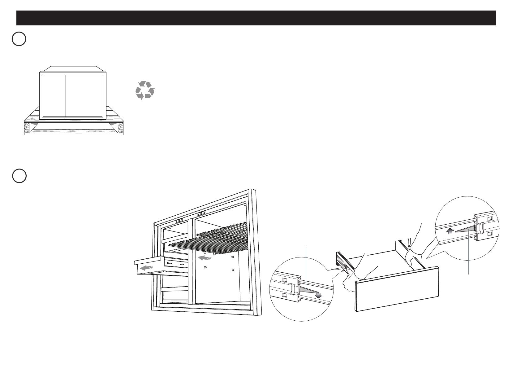
METTEZ L’EMBALLAGE AU REBUT
GAS
ON
GAS
ON
1
2
Fibre washer
Floating nut
Elbow (½” BSP external thread)
Foam Tape
Adhesive side
20 mm
50 mm
+50 mm
NG
ALL Models
Make sure the connection point will be accessible with the cooktop installed.
To enable the gas supply to be readily shut o by the customer, make sure the connection
is tted with an isolating valve close to the cooktop.
Make sure to t the supplied
washer and regulator.
Adjust to obtain a test point
pressure of 1 kPa with the two
semi-rapid burners operating at
highest setting.
Ensure the hose is long enough to allow for removal of cooktop for servicing.
Make sure the connector is located as shown in step 5 CLEARANCE DIMENSIONS.
The hose assembly must be AS/NZS 1869 Class B or D certied, with an Rp ½” (ISO 7‐1) female thread connection.
The hose assembly must be as short as practicable and comply with relevant AS 5601/NZS 5261 requirements.
The hose must not be kinked, subjected to abrasion or permanently deformed.
The hose must not be near or in contact with any hot surfaces
(e.g. base of metal hotlplate, ue, or chassis of underbench oven etc.)
If connecting the gas with a exible hose:
LPG
recessed to 50 mm
check all connections
Make sure to t the supplied
washer and test point adaptor.
Make sure the supply pressure
is regulated to 2.75 kPa, with
the two semi-rapid burners
operating at highest setting.
Washer
Washer
If converting to LPG, see 16 'Converting to a dierent gas type'
To check that the ignition system operates correctly, light each burner by itself, then all burners in combination.
Check for a well‐dened blue ame without any yellow tipping.
If any abnormality is evident, check that the components of the burner assembly are located properly
If proper operation cannot be obtained, contact your nearest F&P Authorised Service Centre.
The cooktop must not be used by the customer until proper operation has been achieved.
yellow tiplifting o
good ame
Arrow
Recyclez de façon
responsable
Le modèle peut être différent des illustrations présentées
8b
RETIREZ TOUS LES TIROIRS ET TOUTES LES TABLETTES POUR ACCÉDER AUX
EMPLACEMENTS DES OUVERTURES DE VIS
Inspectez le(s) produit(s) pour vous assurer qu’aucun dommage n’a été causé lors de l’expédition.
En cas de dommage, communiquez avec l’expéditeur pour faire une demande d’indemnisation.
DCS par Fisher&Paykel n’est pas responsable des dommages causés lors de l’expédition.
REMARQUE: Ne mettez pas au rebut les matériaux d’emballage avant d’avoir terminé l’inspection de
l’appareil.
Utilisez les tiroirs et les tablettes afin de vous assurer qu’ils glissent en douceur.
Examinez les pièces à l’avant afin de vous assurer qu’elles ne présentent aucune bosselure, égratignure
oudécoloration.
Faites preuve de prudence lors de l’ouverture complète des portes de garde-manger. Le cadre extérieur
pourrait marquer le devant des portes.
Pour retirer le(s) tiroir(s)
1
Retirez les tiroirs en les tirant vers
l’extérieur jusqu’à ce que le loquet
deglissière soit visible.
2
Enfoncez doucement le loquet sur
lecôté gauche, tout en soulevant
leloquet sur le côté droit.
3
Sortez le tiroir du cadre.
Remarque: pour éviter d’endommager
lessurfaces, placez les tiroirs sur une surface
stable recouverte d’une serviette ou d’une
nappe protectrice.
Loquet de glissière
gauche
Loquet de glissière
droite
INSTALLATION DU GARDE-MANGER
INSTALLATIONS DANS UN COIN


