Page is loading ...

OMEGA Data Bench Users Manual
Table Of Contents
1.0 Hardware Installation
2.0Software Installation
3.0 Omega Data Bench Overview
4.0 Menu and Setup Controls
5.0 Module Controls
5.1 Ambient Temperture and Thermocouple Controls
5.2 Analog Input Controls
5.3 Digital I/O Controls
6.0 Meter Panel
7.0 Plot Panel
8.0 Logging Configuration Panel
9.0 Performance Statistics
10.0 Related Files
11.0 Data Sheets
OMK-AD612
OMK-AD812
OMK-PG812
OMK-TDA3
OMK-TDA4
OMK-PGT4
OMK-TDA8

OMK-DIO16
OMK-USC
OMK-PGEX1
OMK-MSC01
OMK-TSC5
OMK-DIFF6
12.0 Warranty
1.0 Hardware Installation
Attach the male DB25 connector (plugs) of any of the "Base" modules to any available printer port. Printer ports are female DB25
connectors (receptacles). Use care and do not connect the module's female connector to a male DB25 serial port.
Plug any Add-on modules into the base module. Only the OMK-AD612 and OMK-AD812 modules can use add-ons. Do not plug an add-
on module into any of the other base modules.
Connect the signal(s) directly to the supplied DB25 plug or using a terminal board (STP25). If the signals are located away from the
computer use an extension cable between the computer and the module. Be sure to use an extension cable with all 25 wires and limit the
length to less than 12 feet. Placing the extension cable between the module and the signal connections is not recommended.
A switch box may also be placed between the computer and the module if the extension cable is limited to 6 feet. The module will not,
however, share the printer port (standard port locations only) so the program must be shut down before using the port for other purposes
such as printing.
Do not place an extension cable between the base module and an add-on module.
TOC
2.0 Software Installation
Install the Data Bench software as follows:
1. Insert the CD.
2. From the Startup menu select Run and then Browse. Select the CD and then the CD's "X:\Windows98/95\disk1" folder.
3. Double click the Setup.exe file and then click OK.
4. When the setup program starts, follow the instructions.
TOC
3.0 Omega Data Bench Overview

The Data Bench application provides an integrated desktop that can host up to 8 "Base" modules. Base modules are modules that
connect directly to the printer port. The Base Modules are AD612, AD812, TDA3, TDA4, TDA8 and DIO16.
During program start-up, the standard printer ports are examined for attached Base modules. The standard port locations are
hexadecimal 3BC, 278, 378 and sometimes 2BC.
For each module found, a module setup control is added to the Setup Panel Tab. The Setup Panel also has a provision for adding non-
standard printer ports. Entering a non-standard printer port location will initiate a check for the presents of a Base module. If a Base
module is found, a module Setup Control is added to the Setup Panel. The non-standard printer ports address will be saved when the
program is closed and future program startups will treat the port like a standard printer port.
Once the Base modules have been located, the program will look for an initialization file for each of the ports. If no file is found i.e. the
program has not been previously run, the printer ports Setup Control is set to default settings with the Base module type set to "<null>".
The user must then enter the correct settings. Entering Setup Control setting will generate a new Module Control Panel Tab and all the
displays associated with the module. If an initialization file is found, the setting for the printer port will be restored from the file. If the user
has changed the module attached to the port, the settings must be changed to match. All the settings associated with the printer port and
the attached module(s) is save when the program closes.
The details of setting the Setup Controls and the Module Controls are broken out in sections that follow but before using the Data Bench
Software, you should understand the following basic characteristics of the program.
1. When entering text into data fields, you must press the Enter key to complete the entry. If you do not, the change will be
ignored.
2. When entering numeric values, pressing the Enter key will cause the entry will be checked to verify that it represents a
valid number. If the text is not a valid number representation, the program will "Ding" and the field will be set to a default
value.
3. When entering a file name, a blank entry or an entry starting with a period (".") will be ignored.
4. You should avoid setting the Captions of module or controls to the same name. These Captions are used identify each
of the signals available. For instance if the module caption is "Module 1" and the first analog input caption is "Analog 0",
the signal will be called "Module 1/Analog 0". Setting two module Captions the same or the Captions of two signals
within a module the same will cause confusion. The application will know the difference but chances are you will not.
TOC
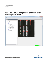
4.0 Menu and Setup Controls

Figure 1
Referring to Figure 1 for number references; Items 2 through 7 make up a Setup Control.
1 Menu – The Menu has the following selections:
File – The File Menu has only one selection Exit. Exit closes the program.
Window – The Window Menu has two selections, Tile and Cascade. Selecting Tile will arrange the module
screens so that each is fully visible. Selecting Cascade will stack the module screens on top of each other,
showing only the Title Bars of the lower screens.
Help – The Help Menu has two selections, About and Bench Help. Selecting About will show a dialog showing the
applications Revision, Release and Copyright. The About dialog also shows statistics on the programs timing
performance. See section Performance Statistics for a more detailed discussion. Selecting Bench Help brings up
this help file.
2 The On checkbox on the Setup Panel when unchecked removes all of the modules controls and displays from the system. You can
use this to remove the controls of a module for any reason, such as when a module has been physical removed. Rechecking the
control will reinstall the module controls and displays.
3 The Port display shows the name i.e. LPT1, LPT2, etc. and the address of the ports base address in hexadecimal. The port names
for the first three ports (LPT1, LPT2 and LPT3) match the names given by the operating system. The names for ports other than
these are derived from the order you entered them. See item 8.
4 The modules Caption or name can be changes by entering a new one. The default Caption is derived from the number of the port
to which the module is attached. The modules Captions appears on the tab to the modules controls and is also pre-fixed to the titles
on all of the modules displays.
5 The Base module selection box is used to set the type of module connected directly to the printer port.

6 The Add-on selection box is used to select the signal-conditioning module plugged into the Base module if there is one.
7 If non-standard printer ports have been added to the system, their base port will have to be entered (in hexadecimal) to tell Data
Bench about them. The program will then check for a module at the specified address. If a module is found, a new Setup Control
will be added. If no module is found the address field will be cleared and you will get the following message.
Once a module has been found, the program will remember to check the address for a module at the next program startup.
8 The tabs are used to select between the Setup Panel and each of the Module Control Panels. When a module is located and the
Base module type is set a new Module Control Panel tab is added.
TOC
5.0 Module Controls
A Module Control Panel is added to the panel tabs for each module installed. Figure 2 shows a typical Module Control Panel (TDA4). The
panel is made up of individual controls that are common to all modules, regardless of its type or Add-on. The following section breaks out
and describes each type of control. For details on a specific module’s controls, refer to the module's specification section. The basic
sections of the Module Control Panel are as follows:

Figure 2
Refer to Figure 2 for matching numbers.
1 Display Panel Control turns Meter Panel, Graphics Panel and Logging Control Panel on or off.
2 Ambient temperature and thermocouple control section.
3 Analog control section.
4 Digital input/output control section.
TOC
5.1 Ambient Temperature and Thermocouple Input Controls

Figure 3
Ambient temperature and thermocouple input controls are added to the Module Control Panel of the TDA3, TDA4, TDA8 Base modules
and AD612 or AD812 Base modules with USC, MSC01-X or TSC5 Add-on modules. Refer to Figure 3 for matching numbers.
1 The On control when unchecked will stop data collection. Since data for the unchecked channel is not collected, it will not be
available for display on the Meter Panel, for plotting on the Plot Panel or Data Logging.
2 The TC box allows the selection of the type of thermocouple connected to the input. Type J, K and T are supported. You can also
select "-" if you want to use the input without temperature conversion. Refer to each specific module specification for detailed input
amplifier circuitry. When using the input without temperature conversion you will be able to edit the display Units; the data Format
and Scale the data input.
3 The inputs Caption or name can be changes by entering a new one. The default Caption is derived from the input type and number.
4 The Units field is used to convert the thermocouple input to temperature. If you are not using the temperature mode i.e. Type is set
to "-", you can edit the Units field as needed. The text you enter will be remembered the next time run the program only if it is
selected when the program is closed.
5 The Format selector sets the number of decimal places used when data is displayed and logged. If the data’s value exceeds the
format selection, the value "+++" or "---" will be displayed or used instead. The format selection is not available when using
temperature conversion.
6 The Avg selector sets the number of data points to average before using the value. A good choice for most applications is 20.
7 The Scale value is used scale the data value before use. The format selection is not available when using temperature conversion.
The scale factor is applied after averaging and before the offset is added. See next Item.
8 The Offset value is added to the scaled data before it is used. The order of the average, scale and offset operator is (average x
scale) + offset. This makes the offset value in "scaled" units.
The linearity of the ambient temperature sensor is very good but the absolute value can vary by ± 2 ° C. Since the thermocouple
temperatures are offset by the ambient temperature, for critical applications, you should adjust the ambient offset using one of the
following methods:
1. Use an independent reference such as thermometer.
2. Use a connected thermocouple at room temperature.
Note that the offset is in the same units as the thermocouple display units i.e. if Units (item 4) is set to ° C, the
offset will be in ° C.
TOC

5.2 Analog Input Controls
Figure 4
Analog input Controls are added to the AD612, AD812, TDA3 and TDA4 Base modules and the AD612 or AD812 Base Module with the
USC or MSC01-X Add-on modules. Refer to Figure 4 for matching numbers.
1 The On control when unchecked will stop data collection. Since data for the unchecked channel is not collected, it will not be
available for display on the Meter Panel, for plotting on the Plot Panel or Data Logging.
2 The Mode selector sets the input mode. The available modes are SE for single ended, D+ for differential with the input with the
Mode selector being the positive input and D- for differential with the input with the Mode selector being the negative input. When
the D+ or D- modes are selected the controls for the second input are removed.
3 The inputs Caption or name can be changes by entering a new one. The default Caption is derived from the input type and number.
4 The Units field can be selected from the standard list or edited as needed. The text you enter will be remembered the next time run
the program only if it is selected when the program is closed.
5 The Format selector sets the number of decimal places used when data is displayed and logged. If the data’s value exceeds the
format selection, the value "+++" or "---" will be displayed or used instead.
6 The Avg selector sets the number of data points to average before using the value. A good choice for most applications is 20.
7 The Scale value is used scale the data value before use. The format selection is not available when using temperature conversion.
The scale factor is applied after averaging and before the offset is added. See next Item.
8 The Offset value is added to the scaled data before it is used. The order of the average, scale and offset operator is (average x
scale) + offset. This makes the offset value in "scaled" units.
TOC
5.3 Digital Input / Output Controls

Figure 5
Digital Input / Output (I/O) Control(s) are present on all Base and Base/Add-on module combinations except the DIO16. Refer to Figure 5
for matching numbers.
1 The On control when unchecked will stop data collection. Since data for the unchecked channel is not collected, it will not be
available for display on the Meter Panel, for plotting on the Plot Panel or Data Logging.
2 The Mode selector sets the data direction of the I/O line to either an input or output. When the output mode is selected, the control
is expanded to show additional control items 3, 4, 5, and 6.
3 When the I/O line is set to output mode, the line can be set low or high under software control based on a comparison test of any
analog, thermocouple or ambient signal source present on the system. Checking the "Set Low If" box enables setting the output
line low and checking the "Set High If" box enables setting the line high. The state of the output line can also be changed from the
modules Meter Panel if the condition that set the output state no longer exists. For example, if the output line is being used to
sound an over temperature alarm when an thermocouple reading exceeds a certain value and the alarm is to be latched on, then
only one of the "Set _ If" criteria’s is used. If the alarm condition is met, the alarm is sounded but will not clear automatically when
the condition is corrected since the other "Set _ If" criteria is not active. The alarm can, however, be cleared from the Meter Panel.
4 Select the signal source to be tested. If the test is active and the signal source is removed or turned off, the following message will
be displayed.
This does not apply to renaming (changing the Caption) of a signal.
5 Select the test criteria. Care should be taken that conflicting tests are not set when using both the "Set Low If" and Set High If"
functions. For example, "Set Low If" signal x = 400 and "Set High If" signal x = 400 have a conflict. Care should also be taken when
using the "=" test criteria as rapidly varying signal may never actually match.

6 Enter the test criteria value.
TOC
6.0 Meter Panels
Figure 7
A Meter Panel is created for each module. The Meter Panel is identified in the title bar with the modules Caption from the modules Setup
Control and the modules Base and Add-on type. The Meter Panel display may be turned on or off with the Display Control at the top of
the Module Panel. Refer to Figure 7 for matching numbers.
1 The individual meter displays have a Caption. The Caption is set from the Module Control Panel.
2 The Individual meters display the latest value of the input. The display has 4 digits and a decimal point. The format for the display is
set from the Module Control Panel. If the value to be displayed exceeds the format specified, "+++" is displayed if the value is
greater than the largest value that can be displayed and "---" if the value is less than the minimum value that can be displayed. For
example, if the format is set to "X.XXX" and the number 10.000 is attempted to be displayed, the result will be "+++".
3 The Units represented by the meter display is shown under the meter.
4 Digital I/O lines set in the output mode have associated toggle buttons. A low state set and indicated by the button being raised and
a high state by the button being inset. When the lines "Set _ If" functions are used, the state of the buttons will change based on the
evaluation of the function. Attempts to manually override the state set by the function will simply be changed to the state resulting
from the function evaluation. For example, if the "Set High If" function has set the line high and the line is then manually set low, the
function will simply set the line back to the high state provided it still evaluates to high.
5 Digital I/O lines used as inputs have their state displayed by LED type indicators.
TOC
7.0 Plot Panel

Figure 8
A Plot Panel is created for each module. The Meter Panel is identified in the title bar with the modules Caption from the modules Setup
Control and the modules Base and Add-on type. The Plot Panel display may be turned on or off with the Display Control at the top of the
Module Panel.
The Plot Panel provides a rudimentary method for viewing data as it is collected. The range (Y-axis) is set using the minimum and
maximum values to be plotted. Both the minimum and maximum plot values can be changed dynamically to zoom in or out. The time
scale (X-axis), however, can not be changed dynamically and changing the time base selection will restart plotting.
The maximum number of points that can be plotted is 8192. When the number of points plotted reaches this limit, the message in Figure
12 is displayed and the plot must be cleared to continue plotting.
The graph is divided into a digital and an analog section. Both sections use the same time base but the digital section is not scalable.
Refer to Figure 8 for matching numbers.
1 Enter the minimum analog value to be plotted. This number must always be less than the maximum analog value (Item 2) and the
program will swap the two values to force this condition.
2 Enter the Maximum analog value to be plotted.
3 Select the plot time base. Changing this selection will cause the plot to restart.
4 The Clear button restarts plotting. The plot can be running when cleared.
5 The Run toggle button starts or stops plotting.
6 The Setup button activates the setup panel. See Figure 10 for details.

7 When the cursor is in a plotted area, the binary values of the digital line are shown.
8 The digital plot area shows the states of the digital lines. This area is not affected by the Y Scale settings. The X axis scale is set
by the Interval selector.
9 The analog plot area shows plots of analog signals. The Y axis range is set from Y Min and Y Max. The Y Min and Y Max value
can be changed while collecting data without any loss of data. The X axis scale is set by the Interval selector.
10 Shows the graph start time.
11 Shows the cursor time value.
12 Shows the graph end time.
13 Shows Y Min.
14 Shows Y Max.
15 Shows the cursor y value.
Figure 9
The Plot Setup Panel, Figure 9, allows signals to be turned on or off and the trace colors to be changed.
1 A check box controls for each signal, turns plotting on or off.
2 A color selector for each signal allows trace color selection. Clicking the traces color selector activate the Color Chooser Panel. See
Figure 11.
Figure 10

The Color Chooser Panel, Figure 10, is used to set the color of a signal trace.
1 Click any color box to select that color and close the dialog or close the using the Close button to make no change.
Figure 11
TOC
8.0 Logging Configuration Panel
Figure 12
The Logging Configuration Panel is used to setup a file to which data is saved, specify the interval at which the data is saved, which
signals are saved and the format of the data file entries. Each time the log interval is reached plain text line representing the data to be
saved is written to the specified file. The format of the saved data consists of an index entry followed by an entry for each of the data

signals selected. A delimiter character separates each entry and the line is terminated with a terminator character. The lines format is
"IndexEntry<delimiter>FirstDataEntry<delimiter>...<delimiter>LastDataEntry<terminator>".
The maximum number of log entries is 8192. When the number of entries reaches this limit, the message in Figure 13 is displayed and
the log file must be Reset or a new file opened to continue plotting.
Refer to Figure 12 for matching numbers.
1 Enter the name of the file where the data is to be saved. Include the path as necessary.
2 Activates the File Open Panel. This is a familiar file selection dialog that is used to select a file instead of typing in the file name.
3 Select the time interval at which the data is to be saved.
4 The Reset button causes the data logging to restart at the beginning of the file. This can be done before or during logging. By
default data is appended to an existing file unless the Reset is pressed.
5 The Log toggle button starts and stops logging.
6 One check box for each signal available on the module allows selection data to be saved. If the data signal is disabled on the
module control panel, the check box will be disabled.
7 Select the index entry for the logged data. The options are Index, a running count of the entries; Elapsed Time, the time in ms since
the program started; System Time, the time of day in hrs:min:sec; and System Date/Time, the date and time of day.
8 Select the delimiter character to be used between each entry in the line. The options are tab, space, comma (,), semi-colon (;) or
colon (:).
9 Select the termination character to be added to the end of each line. The options are Carriage Return; Line Feed or Carriage
Return and Line Feed.
Figure 13
TOC
9.0 Performance Statistics

Figure 14
The About Panel shown in Figure 14 displays statistics about the programs internal operations. As with all programs that rely on operating
systems resources, the program's performance depends on the systems resource loading. At the heart of the program is a task scheduler
that uses a system timer that runs at the highest priority. Every 20 ms the task timer checks to see if any tasks i.e. data conversions, data
plotting or data logging are running. If no tasks are running the scheduler will start the execution of all the tasks required. If previously
scheduled tasks are still running, the scheduler waits 1 ms and checks for task completion again. This 1 mS check continues until all
previously scheduled tasks have executed and a new set of tasks are scheduled. The Scheduler Time Error shows the percent time error
of the scheduler. In the case shown in Figure 14, there are three modules running each of which are plotting and logging data. Module 1
is plotting and logging every 20 ms, Module 2 every 40 ms and Module 4 every 100 mS. As can be seen from Figure 14, the average
scheduling error is 4.2% or .84 mS.
Both the Plot and Log functions have individually set Intervals that are multiples of the task scheduler period of 20 mS. Figure 14, shows
the plot and log time errors for each module. Since Module 1 has an interval of 20 ms, its errors are identical to the scheduler error.
Module 2 has an interval of 40 ms and has a 4.0% error for the plot function and a 3.9% error for the logging function. In time these errors
are 1.6 ms and 1.56 mS. Module 4 has an interval of 100 ms and a 2.1% (2.1 ms) error for both the plot and logging functions.
The time errors will change depending on the speed of the computer, what functions are running and what other applications are running.
If the time errors are unacceptable for a given use, try shutting down other applications and reducing the running functions.
TOC
10.0 Related Files
The application maintains a set of initialization files for the application and each printer port on which a module has been installed. These
files are located in the \bin directory where the application resides. The applications initialization file is named bench.box and the
individual module initialization files are saved as modulex.box where the x is the port number i.e. initialization data for the module
connected to LPT1 is stored in module1.box, etc.
If any of these initialization files should become corrupted simply delete them and the application will build new ones.
There are two lines in the bench.box that can be manually edited. These lines set the maximum number of plot points and the maximum
number of log entries. The lines are always the last two in the file and are originally as follows:
Maximum Plot Points=8192

Maximum Log Entries=8192
Change only the number to the desired value and save the file. The change will take affect the next time the application is run.
TOC
11.0 Data Sheets
Product Specification Omega Engineering, Inc.
Model OMK-AD612
6 Channel Analog Data Acquisition Module with 12 Bit
Resolution
General Description
The OMK-AD612 analog data acquisition module has six analog inputs with twelve-bit resolution. The inputs can be used single ended or
in pairs differentially. An internal reference voltage of 4.096V ± .2%, yields a conversion of 1mV / LSB.
The module is hosted and powered by a PC compatible printer port and no external power supply is required. The Module is compatible
with SPP, BPP, EPP and ECP type printer ports.
The module passes though four bi-directional digital input/output ports from the host printer port. The digital I/O lines can be set or
cleared based on the analog inputs with the bundled software.
Features
•
6 Single Ended or 3 Differential Inputs.
•
12 Bit Resolution, 1mV / LSB.
•
0 to 4.096V Input Range.
•
4 Digital I/O Lines.
•
Printer Port Connected and Powered.

Pin Configuration

Signal Pin #
Analog 0 13
Analog 1 11
Analog 2 9
Analog 3 7
Analog 4 5
Analog 5 3
Digital I/O 0 1
Digital I/O 1 14
Digital I/O 2 16
Digital I/O 3 17
Ground 18-25
Specifications
Analog Inputs
Analog channels 6
Resolution 12 Bits
Analog input range 4.096 V
Analog Input Resistance
10 kΩ
Offset Error
± 3 LSB
Linearity Error
± 0.5 LSB
Gain Error
± 1.0 LSB
Over-voltage Protection
± 15 VDC
Digital I/O
Digital I/O lines 4
Max. current (sinking) 4 mA
Max. current (sourcing) 0.5 mA
Over-voltage protection
± 5V
Physical

Operating temp. range
0 to 70 ° C
Power consumption 50 mW
Conversion Time
With bundled software 20 mS
Application Information
Analog Inputs
The analog inputs can be configured for single ended input or in odd/even pairs for differential input. Table 1 shows the possible
differential configurations. Any combination of single ended and differential configurations may be used. When using the inputs in
differential mode, only the designated plus (+) input supports the sample/hold feature. Therefore, changes in the minus (-) input during
sampling may cause a conversion accuracy error. The input frequency and amplitude on the minus input should be limited to reduce
errors. For an error of 0.25 LSB, the maximum sinusoid input, at 4V-peak amplitude, should be less than 1Hz.
All unused inputs should grounded.
Mode Input Function
D+ Analog0 Differential +
Analog1 Differential -
D- Analog0 Differential -
Analog1 Differential +
D+ Analog2 Differential +
Analog3 Differential -
D- Analog2 Differential -
Analog3 Differential +
D+ Analog4 Differential +
Analog5 Differential -
D- Analog4 Differential -
Analog5 Differential +
Table 1
Digital I/O Lines
The Digital I/O lines are inherited from the printer port implementation. Figure 1 shows a typical circuit for the Digital I/O lines. The output
is driven by an open collector inverter and as the input is a standard inverter. If the output is set low, the input can not be pulled high and
is therefore not usable. Not all printer ports fully support the input function while all do support the output function. Multi-mode (ECP)
printer ports may support the input function in some modes (SPP, BPP) but not in other modes. If the input function is needed but does

not function, change the printer ports mode form the BIOS setup.
Figure 1
TOC
Product Specification Omega Engineering, Inc.
Model OMK-AD812
8 Channel Analog Data Acquisition Module with 12 Bit
Resolution
General Description
The OMK-AD812 analog data acquisition module has eight analog inputs with twelve-bit resolution. The inputs can be used single ended
or in pairs differentially. An internal reference voltage of 4.096V ± .2%, yields a conversion of 1mV / LSB.
The module is hosted and powered by a PC compatible printer port and no external power supply is required. The Module is compatible
with SPP, BPP, EPP and ECP type printer ports.
The module passes though four bi-directional digital input/output ports from the host printer port. The digital I/O lines can be set or
cleared based on the analog inputs with the bundled software.
Features
•
8 Single Ended or 4 Differential Inputs.
•
12 Bit Resolution, 1mV / LSB.
•
0 to 4.096V Input Range.
•
4 Digital I/O Lines.
/