Standard Horizon GX1250S User manual

Type
User manual

This manual is also suitable for

GX1250S
Horizon Eclipse+
25 watt VHF/FM
Marine Transceiver
Owner’s Manual
S
ta
n
d
a
rd
C
om
m
u
ni
c
a
t
i
o
n
s
TABLE OF CONTENTS
GENERAL INFORMATION.....................................................................1
INTRODUCTION......................................................................................1
FCC/DOC INFORMATION.......................................................................1
ACCESSORIES.......................................................................................2
PACKING LIST ........................................................................................2
OPTIONS.................................................................................................2
REPLACEMENT PARTS.........................................................................2
CONTROLS AND INDICATORS.............................................................3
CONTROLS AND CONNECTIONS.........................................................3
INDICATORS...........................................................................................6
INSTALLATION.......................................................................................8
FREQUENCY AND DEVIATION TESTS.................................................8
LOCATION...............................................................................................8
INSTALLATION USING REGULAR MOUNTING BRACKET................10
INSTALLATION USING CMB16 FLUSH MOUNT BRACKET...............10
OPERATION..........................................................................................11
RECEPTION..........................................................................................11
TRANSMISSION....................................................................................11
TRANSMIT TIME-OUT TIMER (TOT)....................................................12
USA, INTERNATIONAL AND CANADIAN MODES...............................12
WEATHER CHANNELS.........................................................................12
SCANNING............................................................................................13
PRIORITY SCANNING..........................................................................13
WEATHER ALERT.................................................................................14
EMERGENCY CHANNEL 16.................................................................15
CHANNEL 9...........................................................................................15
OPERATING ON CHANNEL 13 ............................................................15
OPERATING ON CHANNEL 67 ............................................................15
MAINTENANCE.....................................................................................16
SPECIFICATIONS.................................................................................17
GENERAL..............................................................................................17
TRANSMITTER......................................................................................17
RECEIVER.............................................................................................17
FIGURES
1. Controls and Connectors .....................................................................4
2. Indicators..............................................................................................6
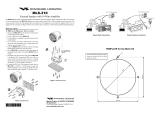
3. General Installation..............................................................................9
4. Regular Mounting Bracket....................................................................9
5. Optional CMB16 Mounting Bracket......................................................9
1 GENERAL INFORMATION
1.1 INTRODUCTION
The Standard Communications Corp. (SCC) GX1250S Eclipse+ is a VHF
transceiver designed for use in the frequency range of 156.050 to
163.275 MHz. It requires 13.8 VDC for operation.
The transceiver has 65 channels: 55 marine and 10 weather. The 55
marine channels are switchable to comply with either USA, International,
or Canadian regulations. It has an emergency channel 16 which can be
immediately selected from any channel by pressing the red 16/9 key.
Weather channels can be also be accessed immediately by pressing the
WX key.
The power output is 25 watts in high range and 1 watt in the low range.
These ranges are manually selected by the front-panel H/L key, except
on channels where low range power is mandatory. On these channels
low range is automatically selected.
1.2 FCC/DOC INFORMATION
The following data pertaining to the transceiver is necessary to fill out the
license application.
FCC Type Accepted...............................................................FCC Part 80
Output Power .........................................1 watt (Low) and 25 watts (High)
Emission ............................................................................................16F3
Frequency Range...............................................156.050 to 163.275 MHz
FCC Type Number......................................................................APV0493
DOC Type Approval........................................................363822161LVCA
Owner's Manual
GX1250S Page 1
Additional FCC and DOC data, including licensing requirements,
are contained in the companion document titled OWNER’S
MANUAL SUPPLEMENT. The document also contains charts for
VHF channel assignments, transceiver procedures,
maintenance, factory service information, and warranty data.
2 ACCESSORIES
2.1 PACKING LIST
When the package containing the transceiver is first opened, please
check it for the following contents:
• GX1250S Eclipse+ Transceiver.
• CMP348W Microphone (Attached to the transceiver).
• Mounting Bracket and attaching hardware.
• Power Cable.
• Owner’s Manual.
• Owner’s Manual Supplement.
• Hanger Kit for Microphone.
2.2 OPTIONS
CMB16......................................................................Flush-Mount Bracket
201S ...........................Remote Extension Speaker with RCA Phono Plug
201SZ......................................................................Flush-mount Speaker
101...............................................................................Extension Speaker
2.3 REPLACEMENT PARTS
Microphone Assembly ..........................................................MP51000240
Microphone Hanger...............................................................277X155020
Mounting Bracket...................................................................175B160020
Mounting Bracket Knob.........................................................414C154022
Volume Knob.........................................................................175B154500
Squelch Knob ........................................................................175B154010
Owner's Manual
GX1250SPage 2
3 CONTROLS AND INDICATORS
Refer to Figure 1 for the location of the following controls, indicators, and
connections:
3.1 CONTROLS AND CONNECTIONS
qq
POWER SWITCH/VOLUME CONTROL
Turns the transceiver on and off, and adjusts the volume.
ww
SQUELCH CONTROL
Sets the point at which random noise on the channel does not
activate the audio circuits but a received signal does. This point is
called the squelch threshold. Further adjustment of the squelch
control degrades reception of wanted transmissions.
ee
KEY PAD
UP KEY
Selects the desired channel. Each press increases the channel
number. When held down, channels increase continuously.
DN KEY
Selects the desired channel. Each press decreases the channel
number. When held down, channels decrease continuously.
H/L KEY
Toggles between high and low transmitting power. This key does not
operate on “low power only” and transmission-inhibited channels.
When held down while the transceiver is on channel 13 or 67, the
power temporarily enters high range.
WX KEY
Immediately recalls a weather channel 01 from any channel location.
Reverts the transceiver to the previous channel when pressed twice
after 16/9 key is pressed.
Owner's Manual
GX1250S Page 3
Owner's Manual
GX1250SPage 4
Horizon ECLIPSE +
UP
H
/
L SCAN
DN WX
16
/
9
R
/
D
SQL
VOL
U I C
DN
UP
qq
ww
ee
rr
tt
yy
uu
ii
oo
!!00
Figure 1. Controls and Connectors
!!11
FRONT PANEL
REAR PANEL
MICROPHONE
FRONT VIEW
TOP VIEW
!!22
SCAN KEY
Starts and stops scanning programmed channels. Holding down this
key, scanning channels are programmed.
16/9 KEY
Immediately recalls channel 16 from any channel location. Holding
down this key recalls channel 9. When held down while pressing the
WX key, changes the mode from USA to International or Canadian.
When held down while turning the power on, microprocessor is reset
and scan channels are erased.
rr
SPEAKER
tt
LIQUID-CRYSTAL DISPLAY (LCD)
See Section 3.2 for Indicators.
yy
ANTENNA JACK
Connects the antenna to the transceiver. Use a marine VHF antenna
with an impedance of 50 ohms.
uu
DC INPUT CABLE
Connects the transceiver to a DC power supply of 13.8 V.
ii
EXTERNAL SPEAKER JACK
Connects an optional external speaker to the transceiver. Use a
speaker with an impedance of 4 or 8 ohms, with an RCA phono plug.
oo
MICROPHONE
Transmits a voice message.
!!00
PUSH-TO-TALK (PTT) SWITCH
Activates transmission.
Owner's Manual
GX1250S Page 5
!!11
UP KEY
Selects the desired channel. Each press increases the channel
number. When held down the channel numbers increase
continuously.
!!22
DOWN KEY
Selects the desired channel. Each press decreases the channel
number. When held down the channel numbers decrease
continuously.
3.2 INDICATORS
The LCD on the transceiver has several symbols and indicators that
should be understood by the user before operating the unit. Figure 2
shows all of these symbols and indicators, although it is not possible to
see them at the same time.
U/I/C Indicator
Indicates the mode of operation (USA, International or Canadian) for
a particular channel.
WX Indicator
Indicates a weather channel.
Owner's Manual
GX1250SPage 6
A
HI
WX
LO
TX
U
I
C
Figure 2. Indicators
TX Indicator
Transmission indicator. The TX indicator appears when th PTT switch
is pressed and it is O.K. to transmit.
MEM Indicator
Indicates the channel is memorized in the transceiver’s memory.
A Indicator
Indicates a simplex channel in USA or Canadian mode whose
counterpart in the International mode is a duplex channel.
7-SEGMENT Display
Displays the channel number in use.
HI/LO Indicator
Indicates the power setting. “HI” 25 watts and “LO” 1 watt. This
display is blank if a transmission-inhibited channel is selected.
Owner's Manual
GX1250S Page 7
Owner's Manual
GX1250SPage 8
4 INSTALLATION
4.1 FREQUENCY AND DEVIATION TESTS
FCC regulations require that the transceiver’s deviation and frequency
be tested before initial installation or operation. This test should be
performed by a Certified Marine Technician.
4.2 LOCATION
1. The transceiver can be mounted at any angle. Choose a mounting
location that:
• is far enough from any compass to avoid erroneous compass
reading due to the speaker magnet
• provides protection from sea spray and rain
• provides accessibility to the front panel controls
• allows connection to a power source and an antenna
• has nearby space for installation of a microphone hanger
2. Install the unit in accordance with paragraph 4.3 or 4.4.
In each appears an instruction to connect the power supply and
antenna. Where that appears, the following three steps should be
performed:
a. At the rear of the transceiver, connect the antenna cable to the
antenna jack. The antenna must have a PL259 connector. RG8 or
RG213 coaxial cable must be used if the antenna is 25 feet or
more from the transceiver. RG58 cable can be used for distances
less than 25 feet.
b. Connect the red power cord to a 13.8 VDC ± 20 % power source.
Connect the black power cord to negative ground. See Figure 3 for
this step .
c. It is advisable to have a Certified Marine Technician check the
power output and the standing wave ratio of the antenna after
installation.
Owner's Manual
GX1250S Page 9
Figure 3. General Installation
Figure 4. Regular Mounting Bracket
Figure 5. CMB16 Mounting Bracket
SPEAKER
(OPTIONAL)
BATTERY
WATERPROOF
DECK OUTLET
Owner's Manual
GX1250SPage 10
4.3 INSTALLATION USING REGULAR MOUNTING
BRACKET
1. Mount the bracket using the washers, nuts, and long hex head bolts.
2. Thread the mylar washers onto the mounting bracket knobs.
3. Position the transceiver within the bracket arms, matching the
transceiver notches to obtain the desired positioning.
4. Secure the transceiver to the brackets with the mounting knobs (see
Figure 4).
5. Connect the antenna and power cables (and optional speaker) to the
transceiver.
4.4 INSTALLATION USING CMB16 FLUSH MOUNT
BRACKET (Optional)
Refer to Figure 5 for the following procedure.
1. Use the template supplied with the CMB16 to mark the location
(inner template) where the rectangular hole (5-5/16 by 2-1/16 inches)
is to be made. Confirm the space behind the dash or panel is deep
enough to accommodate the transceiver. There should be at least
1/2 inch between the transceiver’s heatsink (fins) and any wiring,
cables or structures.
2. Cut out the rectangular hole and insert the transceiver.
3. Fasten the brackets to the sides of the transceiver with the lock
washer nut combination, so the mounting screw base faces the
mounting surface (see Figure 5).
4. Turn the adjusting screws to adjust the tension so the transceiver is
against the mounting surface.
5 OPERATION
After the transceiver has been installed (see section 4), ensure the
power supply and antenna are properly connected.
5.1 RECEPTION
1. Turn the POWER SWITCH/VOLUME CONTROL on.
2. Turn the volume control knob to the desired level.
3. Turn the SQUELCH CONTROL knob fully counterclockwise. This
state is known as “squelch off”.
4. Turn up the volume until noise or audio from the speaker is at a
comfortable level.
5. Select a channel that has no signal being received (no one is
transmitting on the channel). Only noise should be heard.
6. Slowly turn the SQUELCH CONTROL knob clockwise and stop
immediately after the noise disappears. This condition is known as
the “Squelch Threshold”. If the SQUELCH CONTROL knob is turned
clockwise past this point, weak signals are not received. No noise
and no signals are heard until a signal is received that exceeds the
squelch threshold.
7. To change channels, press the UP or DN key. Sometimes, a slight
adjustment of the squelch threshold needs to be made, because
some channels have a higher noise level than others.
Please refer to the Owner’s Manual Supplement for a complete
listing of all USA, International and Canadian VHF Marine channels
and their usages.
5.2 TRANSMISSION
1. Perform steps 1 through 7 of RECEPTION.
2. Before transmitting, monitor the channel and make sure it is clear.
THIS IS AN FCC REQUIREMENT!
Owner's Manual
GX1250S Page 11
Owner's Manual
GX1250SPage 12
3. Press the PTT (push - to - talk) switch. The TX indicator in the LCD is
displayed.
4. Speak slowly and clearly into the microphone, hold the microphone
about 1/2 to 1 inch away from your mouth.
5. When the transmission is finished, release the PTT switch.
6. Refer to the OWNER’S MANUAL SUPPLEMENT for standard
transceiver operating procedures.
5.3 TRANSMIT TIME - OUT TIMER (TOT)
When the PTT switch is held down, transmission time is limited to 5
minutes. This prevents prolonged unintentional transmissions. About 10
seconds before automatic transmitter shutdown, a warning beep is heard
from the speaker. The transceiver then automatically switches to the
receiving mode, even if the PTT switch is still held down. Before
transmitting again, the PTT switch must first be released and be pressed
again.
5.4 USA, INTERNATIONAL AND CANADIAN MODES
1. To change the modes, hold down the 16/9 key and press the WX
key. The mode changes from USA to International to Canadian with
each press of the WX key.
2. “U” is displayed for the USA mode, “I” is displayed for International
mode, and “C” is displayed for Canadian mode.
3 Refer to the OWNER’S MANUAL SUPPLEMENT for the allocated
channels in each mode.
5.5 WEATHER CHANNELS
1. To receive a weather channel, press the WX key. The transceiver
changes channel to the weather channel 01.
2. Press the UP or DN key to move to other weather channels.
3. To exit from the weather channels, press the WX key. The transceiver
returns to the channel it was on prior to the weather channel.
5.6 SCANNING
1. Adjust the SQUELCH CONTROL until the background noise
disappears.
2. Select the desired channel to be scanned using the UP or DN key.
3. Hold down the SCAN key until “MEM” is displayed.
4. Repeat steps 2 and 3 for the channels to be scanned.
5. To start scanning, press the SCAN key. Scanning proceeds from
the lowest to the highest programmed channel number and stops on
a channel where a transmission is received.
6. To stop scanning, press the 16/9, WX, SCAN key, or PTT switch.
7. To DELETE a channel from the transceiver’s memory, hold down the
SCAN key while the memorized channel is displayed. “MEM” is
deleted.
5.7 PRIORITY SCANNING
Emergency channel 16 can be set as the priority channel for scanning
by performing the following:
1. Turn off the transceiver power.
2. Press and hold the SCAN key and turn the power back on. A “p” will
be shown to the left of “16” on the display to indicate that priority
scan is enabled.
NOTE
To scan or priority scan, 2 or more channels must be memorized in
scan memory. See section 5.6 in the Owner’s Manual.
3. To start scanning, press the SCAN key. Scanning will proceed
between the memorized channels and priority channel 16.
4. For example, channels 06, 07, and 08 are memorized in the transceiver’s
memory, priority scanning will proceed in the following sequence:
Owner's Manual
GX1250S Page 13
CH06
Priority
Channel
16
CH07 CH08
Priority
Channel
16
Priority
Channel
16
5. Even when the transceiver stops and listens to the signal of a
memorized channel, the transceiver will DUAL WATCH between this
channel and the priority channel.
6. To disable priority scanning, turn off the transceiver power. Press
and hold the SCAN key and turn the power back on. The “p” will
disappear from the display to indicate that priority scan is disabled.
5.8 WEATHER ALERT
In the event of extreme weather disturbances such as storms and
hurricanes, NOAA (National Oceanic and Atmospheric Administration)
sends a weather alert accompanied by a 1050 Hz tone and subsequent
weather reports on the weather channels. The transceiver is capable of
receiving this alert if the following steps are performed:
1. Program weather channels into the transceiver’s memory for
scanning. Follow the same procedure as used for regular channels in
Section 5.6.
2. Press the SCAN key to start a scan.
3. The programmed weather channels are scanned along with the
regular programmed channels. However, the scan does not stop for
normal weather broadcast.
4. When an alert is received on a weather channel, scanning stops and
the transceiver enters the WEATHER ALERT MODE.
5. When the transceiver is in the WEATHER ALERT MODE, a loud
tone is sounded.
6. Press the WX key to stop the alert tone and receive the voice
information on the weather channel.
Owner's Manual
GX1250SPage 14
5.9 EMERGENCY CHANNEL 16
1. To select the emergency channel, press the 16/9 key from any
channel.
2. Transmit your emergency signal in the same manner as on regular
channels. If you can not contact anyone on channel 16, switch to
another channel.
3. See the OWNER’S MANUAL SUPPLEMENT for additional
emergency operating practices.
5.10 CHANNEL 9
1. Channel 9 is used as a hailing channel for initial, non-emergency
contact with other vessels. Hold down the 16/9 key to select channel
9.
5.11 OPERATING ON CHANNEL 13
Channel 13 is used at docks, bridges and for maneuvering in port.
Messages on this channel must concern navigation only, such as
meeting and passing in restricted waters. Messages must be short and
low power used.
In emergencies and when approaching blind river bends, high power is
allowed. Hold down the H/L key to temporarily switch to high power. Hi
power can only be accessed in USA or Canadian modes
.
5.12 OPERATING ON CHANNEL 67
When channel 67 is used for navigational bridge-to-bridge traffic
between ships, high power may be temporarily used in the USA mode,
by holding down the H/L key.
Owner's Manual
GX1250S Page 15
Owner's Manual
GX1250SPage 16
6 MAINTENANCE
For preventive maintenance and instructions on obtaining factory service,
please refer to the OWNER’S MANUAL SUPPLEMENT. For general
troubleshooting, refer to the Troubleshooting Chart.
TROUBLESHOOTING CHART
PROBABLE
CAUSE
No DC voltage to
the transceiver or a
blown fuse.
Reversed power
connections.
Engine noise.
Incorrect plug on
speaker cable.
No problem.
Channel mode.
Antenna
REMEDY
Check power cable for DC
voltage or the replace the 6 A
250 V fuse.
Be sure the RED wire is
connected to POSITIVE battery
terminal and BLACK wire to
NEGATIVE terminal. If the
transceiver still blows the fuse,
contact your SCC Dealer.
Reroute DC power cables away
from engine. Add noise
suppressor to the power cable.
Change to resistive spark plug
wires and/or add an alternator
whine filter.
The external speaker jack
accepts only RCA phono plugs
.
Normal transceiver operation
causes internal speaker cut-off
when external speaker is
plugged in.
The transceiver may be tuned
to a duplex channel meant for
ship-to-shore radiotelephone
communications.
Have antenna checked or test
the transceiver with another
antenna. If problem persists,
contact your SCC Dealer.
SYMPTOM
Transceiver fails to
power up.
Transceiver blows fuse
upon connection of the
power supply.
Popping or whining
noise from speaker while
the engine runs.
External speaker plug
does not fit into jack.
Internal speaker turns off
when external speaker is
plugged in.
Transceiver transmits
but does not receive.
Transceiver transmits on
low power only.
7 SPECIFICATIONS
Performance specifications are nominal, unless otherwise indicated, and
are subject to change without notice.
7.1 GENERAL
Frequency Range..............................................................156.050 to 163.275 MHz
Channels...............................................................65 total: 55 marine + 10 weather
Input Voltage ................................................................................13.8 VDC ± 20 %
Current Drain:
Standby...............................................................................................0.5 A
Receive ...............................................................................................1.5 A
Transmit.........................................................................6 A (Hi); 1.7 A (Lo)
Physical Characteristics................................................2.52” H x 5.91” W x 5.28” D
(64 mm x 150 mm x 134 mm)
1.68 Ib. (0.76 Kg)
FCC Type Acceptance Number ................................................................APV0493
DOC Type Approval Number.....................................................363822161LVCA
7.2 TRANSMITTER
RF Output...................................................................................25 W (Hi); 1W (Lo)
Conducted Spurious Emissions.............................................65 dB (Hi); 50 dB (Lo)
FM Hum and Noise .................................................................................40 dB min.
Audio Response......................................within +2/-8 of 6 dB/octave pre-emphasis
Audio Distortion..................................................................................................5 %
Modulation........................................................................................................16F3
Frequency Stability (-20° to +50°C)........................................................± 0.0005 %
7.3 RECEIVER
Sensitivity:
20 dB Quieting...................................................................................0.4 µV
12 dB SINAD...................................................................................0.35 µV
Squelch Sensitivity (Threshold)......................................................................0.2 µV
Bandwidth
Acceptable Radio Frequency Displacement.................................± 4.5 kHz
Selectivity:
Spurious and Image Rejection...........................................................70 dB
Intermodulation and Rejection at 12 dB SINAD Sensitivity................65 dB
Audio Output 5% Distortion................................................................................4 W
Audio Response..........................................................within +2/-8 of a 6 dB/octave
de-emphasis characteristic at 300 to 3000 Hz
Frequency Stability (-20° to +50°C)..........................................................± 0.001 %
Channel Spacing...........................................................................................25 kHz
Owner's Manual
GX1250S Page 17
S
ta
n
d
a
rd
C
om
m
u
ni
c
a
t
i
o
n
s
Standard Communication Corp.
P.O. Box 92151
Los Angeles, CA 90009-2151
Telephone 310/532-5300
© STANDARD COMMUNICATIONS CORP. 1998
All Rights Reserved
Printed in Japan
03/1999 175B851012
  • Page 1 1
  • Page 2 2
  • Page 3 3
  • Page 4 4
  • Page 5 5
  • Page 6 6
  • Page 7 7
  • Page 8 8
  • Page 9 9
  • Page 10 10
  • Page 11 11
  • Page 12 12
  • Page 13 13
  • Page 14 14
  • Page 15 15
  • Page 16 16
  • Page 17 17
  • Page 18 18
  • Page 19 19
  • Page 20 20

Standard Horizon GX1250S User manual

Type
User manual
This manual is also suitable for

Ask a question and I''ll find the answer in the document

Finding information in a document is now easier with AI