2
. This GFCI device is to be used on 120V/60Hz circuit only (such as normal household electrical distribution system).
3
. Ground fault circuit interrupters, whether this device or any other, cannot protect against electrical shock resulting from contact
with both hot and neutral wires of the electrical circuit nor against defects in any wiring supplying the device.
4. DO NOT USE IFTHE BUTTON BOOTS OR CASE OR CORD HAVE BEEN DAMAGED.
5
. Test frequently and at least before each use of load equipment to insure correct operation.
6. The GFCI is designed as a protective device. Do not use as an off/on switch.
7. Do not use on circuit with life support apparatus.
L
IMITED ONEYEAR WARRANTY
Pass & Seymour/Legrand will remedy any defect in workmanship or material in Pass & Seymour/Legrand products which may
develop under proper and normal use within one year from the date of purchase by a consumer. (1) by repair or replacement,
o
r at Pass & Seymour/Legrand’s option, (2) by return of the amount equal to the consumer’s purchase price. Such remedy
is IN LIEU OF ANY AND ALL EXPRESSED OR IMPLIED WARRANTIES OF MERCHANTABILITY OR FITNESS FOR A
PARTICULAR PURPOSE. Such remedy by Pass & Seymour/Legrand does not include or cover cost of labor for removal
o
r reinstallation of the product. ALL OTHER FURTHER ELEMENTS OF DAMAGE (INCIDENTAL OR CONSEQUENTIAL
D
AMAGES) FOR BREACH OF ANY AND ALL EXPRESSED OR IMPLIED WARRANTIES INCLUDING WARRANTIES
OF MERCHANTABILITY OR FITNESS FOR A PARTICULAR PURPOSE ARE EXCLUDED HEREBY. (Some states do
not allow disclaimer or exclusion or limitation of incidental or consequential damages, so the above disclaimers and limitation
o
r exclusion may not apply to you.) ANY IMPLIED WARRANTIES INCLUDING WHERE REQUIRED WARRANTIES OF
MERCHANTABILITY OR FITNESS FOR A PARTICULAR PURPOSE SHALL BE LIMITED TO THE ONE YEAR PERIOD
SET FORTH ABOVE. (Some states do not allow limitation on how long an implied warranty lasts, so the above limitation
m
ay not apply to you.)
T
o ensure safety, all repairs to Pass & Seymour/Legrand products must be made by Pass & Seymour/Legrand or under
its specific direction. Procedure to obtain performance of any warranty obligation is as follows: (1) Contact Pass &
Seymour/Legrand, P.O. Box 4822, Syracuse, NY 13221 for instructions concerning return or repair; (2) return the product
t
o Pass & Seymour/Legrand, postage paid, with your name and address and a written description of the installation or use
of the Pass & Seymour/Legrand product, and the observed defects or failure to operate, or other claimed basis for dissatisfaction.
T
his warranty gives you specific legal rights and you may also have other rights which vary from state to state.
MODEL NUMBERS
AUTO- MANUAL
RESET RESET
1
5 Amp 1594-CMA 1594-CMM
G
ENERAL
Pass & Seymour/Legrand’s portable ground fault circuit interrupter (GFCI) provides personnel ground fault protection. Conventional
over-current protection devices such as fuses and circuit breakers cannot protect people from electrical shock. Those devices are
d
esigned to disconnect the power when currents of several amperes flow from the hot wire to ground. However, currents as low as
a few milliamperes can be dangerous to normal healthy human beings. One ampere equals
1000 milliamperes.
M
any electrical shocks occur when the path of current flow is from the hot wire through the metal housing of a defective tool or
a
ppliance, through the body of a human being to ground. Because of the resistance of the human body to electrical current flow,
the current will be quite low relative to that required to cause conventional over-current protection devices to function. However,
it is likely to be high enough to cause a painful or possibly lethal electric shock to a human being.
P
ass & Seymour/Legrand’s portable GFCI is designed to remove power from the equipment loads when these loads have a
potentially lethal ground current in excess of six milliamperes. Normal loads will draw current from the Hot Conductor (black wire)
and return it to the power source through the Neutral Conductor (white wire). Faulty loads can return some of the current to the
p
ower source through a ground path such as a water pipe, gas pipe, wet floor, third conductor (green wire), or worst of all, through
a person who is in contact with an extrinsic ground.
The Pass & Seymour/Legrand portable GFCI’s rugged construction allows it to be used in outdoor or indoor locations, where
g
round fault protection is desired. When energized by actuation of the reset button, it will conveniently supply power to any power
t
ool or appliance whose load requirement does not exceed rated voltage and currents.
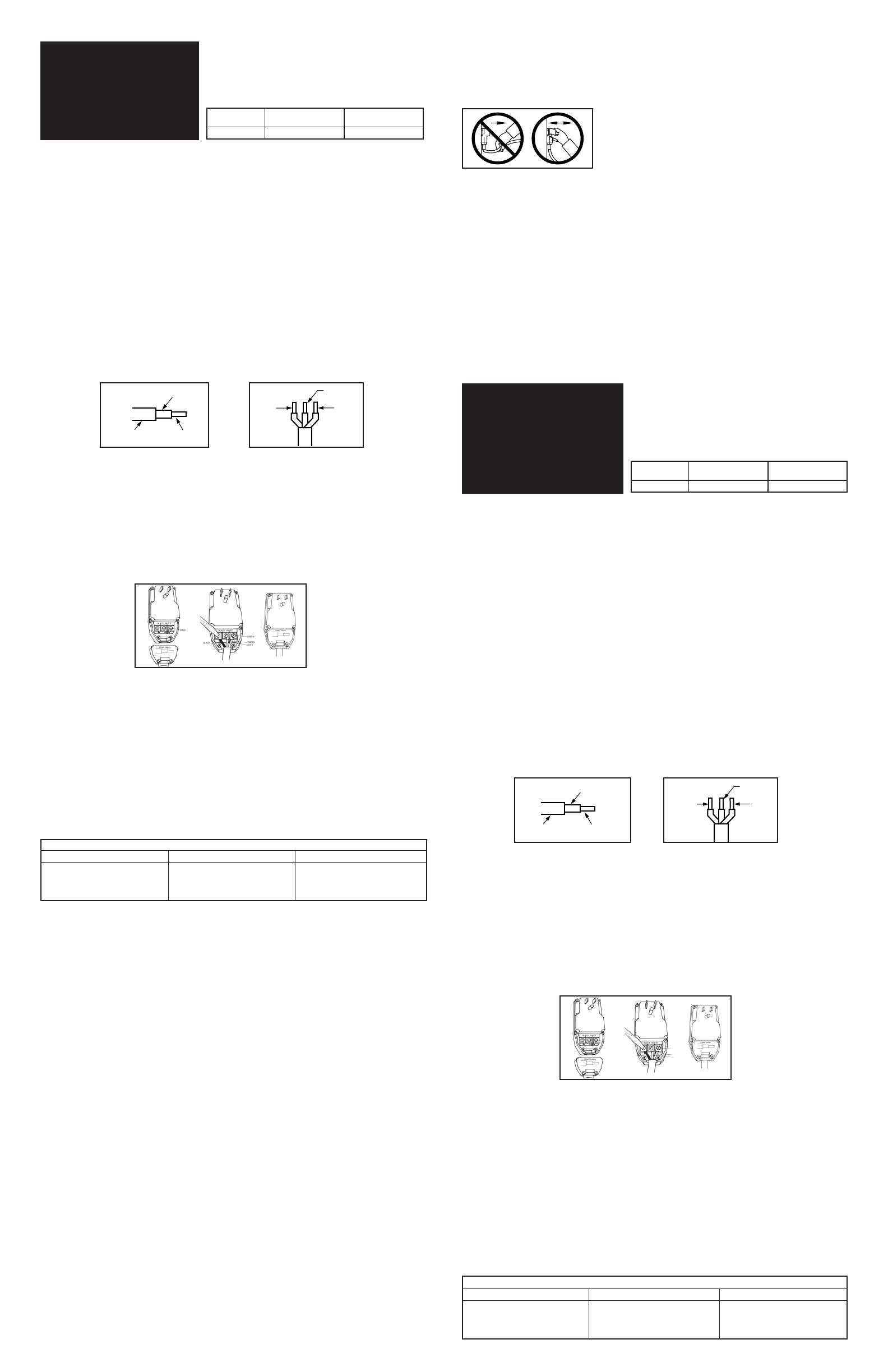
WIRING INSTRUCTIONS
1
. Remove strain relief/cover from rear of unit. Lay wire to be stripped against the strip gage on the strain releif cover and mark
t
he strip length on the outer jacket. Carefully cut around the outer jacket and conductors, and prepare as noted in Fig. 1
and 2. IMPORTANT: When cutting and stripping outer jacket, if accidental cutting of conductor insulation occurs, cut through
i
njured cord and repeat instruction number 1.
2. IMPORTANT: Wires must be connected to the correct terminals, otherwise an electric shock hazard may exist. Attachment is
m
ade by first loosening the terminal screws so adequate space is provided between the underside of the square washer and
the top of the brass terminal to accept the wire. Connect the black (line) wire to the terminal marked Black. Connect the white
(
neutral) wire to the terminal marked white and connect the green (ground) wire to the green colored terminal. Fully insert the
w
ires between the appropriate square washer and brass terminal and tighten the terminal screws securely (8 LBF-IN).
W
ARNING: DO NOT capture the conductor insulation, also, make sure no loose strands of wire protrude outside the terminal
a
rea which could contact strands from the other conductors. See Fig. 3 and 4.
A
fter installing the leads to the terminals, apply RTV silicon rubber sealant over the terminals by squeezing the half-ounce
tube of RTV over the terminals and any exposed conductors in the wiring compartment. The coating thickness should be
a
pproximately one eighth inch. Use the entire contents of the tube then discard the empty tube. NOTE: Normal application
requires that at least three fourths of the tube be used for coating.
C
AUTION: Very Important – Only use supplied and approved RTV.
3. Locate the strain relief/cover over the two screw posts and insert both screws. While alternating between the strain relief
s
crews gradually tighten the strain relief while holding the outer jacket of the wire fully into the unit until it is held securely.
(
See Fig. 5)
The strain relief/cover should be installed immediately without waiting for the RTV to cure. The cure time at room temperature
i
s approximately 24 hours. The GFCI may be used as soon as the strain relief/cover is secured.
CAUTION: RTV irritates eyes. RTV may irritate nose, throat, and respiratory tract. RTV may cause allergic skin sensitization.
Avoid eye contact with RTV. Avoid prolonged breathing of RTV vapors. Avoid prolonged or repeated skin contact with RTV.
U
se RTV with adequate ventilation. In case of eye contact with RTV, wipe off RTV and flush eye with water. During RTV cure,
methanol is released. Keep RTV out of reach of children.
W
ARNING
It is most important to use the correct size wire for the application. Otherwise a fire hazard could exist (as with any attachable
p
lug). If the GFCI is being connected to an appliance whose power cord was installed by the appliance manufacturer, it is
assumed the correct size wire has been used, and this can be connected to the GFCI. If the user is attaching a power cord to the
GFCI that has not been connected to an appliance by the manufacturer, before choosing the wire size first determine the ampere
r
equirement of the appliance and then refer to the following chart. If the cord is for general use, as in an extension cord, then the
wire size used must be at least 14 AWG (15 AMP rating).
If cord length longer than 50 ft is used, increase the wire gage to the next size. (i.e., 13 AMP with over 50 ft of power cord —
use 14 AWG 15 AMPS with over 50 ft cord – use 12 AWG)
TYPE AND SIZE OF CORD USABLE WITH THIS PRODUCT.
Cord diameter should be in the range of .30 (5/16) to .46 (15/32) inch to fit the wire clamp. Following is a list of recommended
cord types.
SJ, SJO, SJT, or equal. 18/2 through 12/3
S, SO, ST, of equal 18/2 through 16/3.
INSTALLATION AND OPERATION – MANUAL RESET VERSION
1. Connect the power cord to the GFCI in accordance with cord attaching instructions.
2. Plug unit into a suitable 120 VAC power socket.
3. Press and release the Reset Button.
4. Verify that the red band at the base of the Reset Button is not visible. (Note: This denotes that output power is available.)
5. Press the Test Button.
6. Verify that the red band on the Reset Button appears.
7. Press and release the Reset Button.
8. Verify that the red band is not visible.
9. Connect the desired load equipment to cord output receptacle and operate equipment normally.
INSTALLATION AND OPERATION – AUTO RESET VERSION
1. Connect the power cord to the GFCI in accordance with cord attaching instructions.
2. Plug unit into 120 VAC power socket protected by fuse or circuit breaker.
3. Unit will automatically become energized and red band at base of reset button not visible.
4. Press the Test Button.
5. Verify that the red band on the Reset Button appears.
6. Press and release the Reset Button.
7. Verify that the red band is not visible.
8. Connect the desired load equipment to cord output receptacle and operate equipment normally.
WARNINGS
1. If the GFCI fails to trip when the Test button is pressed (lamp indicator fails to turn off) or, if the GFCI fails to reset when the
Reset button is pushed in (lamp indicator fails to remain lit), the device should be replaced.
2. If the GFCI test properly without any appliance plugged into it but trips each time the appliance is plugged in, the appliance
has a ground fault and needs to be repaired or replaced. DO NOT BYPASS THE GFCI. IF THIS CONDITION OCCURS,
A REAL SHOCK HAZARD MAY EXIST.
NOTES
Note 1:
Pass & Seymour/Legrand’s portable power plug models will provide protection against ground faults when used with a
2-wire outlet receptacle and a 3-wire to 2-wire adapter. It is always desirable when possible to use a 3-wire grounded receptacle
because a ground provides additional protection against electrical shock hazard. The adapter should be of the type that can be
grounded to the outer mounting plate screw.
Note 2:
The GFCI does not sense ground faults in the input conductors, therefore it is recommended that if any extension cords
are used, they should be connected between the GFCI’s output and the tool or appliance to be powered. Your GFCI is now ready
to test and use.
CAUTIONS
1. Do not connect any electrical cord longer than 250 feet to the GFCI output receptacle in order to avoid possibility of nuisance
tripping.
NÚMEROS DE MODELOS
REPOSICIÓN REPOSICIÓN
AUTOMÁTICA MANUAL
1
5 Amp. 1594-CMA 1594-CMM
INSTALLATION AND
O
PERATING
INSTRUCTIONS
PORTABLE
G
ROUND FAULT CIRCUIT
INTERRUPTER (GFCI)
NOTE:
Remove from receptacle by grasping the body of the GFCI.
Not the cord.
C
ONDUCTOR INSULATION
(
BLACK, WHITE OR GREEN)
OUTER JACKET CONDUCTOR
WIRE USAGE CHART
A
MPERES (WATTS)
15 AMPS (1800 WATTS)
13 AMPS (1560 WATTS)
10 AMPS (1200 WATTS)
W
IRE GAGE SIZE
14 AWG
16 AWG
18 AWG
M
AX WIRE LENGTH
50 FEET
50 FEET
50 FEET
FIG. 1
FIG. 2
FIG. 5
FIG. 3
FIG. 4
G
ENERAL
Los interruptores de circuito accionado por corriente de pérdida a tierra (GFCI) portátiles de Pass & Seymour/Legrand protegen
l
as personas contra las fallas a tierra. Los dispositivos convencionales de protección contra la sobrecorrientes tales como
fusibles y disyuntores no pueden proteger a las personas contra los choques eléctricos. Estos dispositivos están diseñados
p
ara desconectar el suministro eléctrico cuando corrientes de varios amperios fluyen del cable cargado a tierra. Sin embargo,
c
orrientes de sólo unos pocos miliamperios pueden ser peligrosas para personas normales y saludables. Un amperio es igual a
1000 miliamperios.
M
uchos choques eléctricos ocurren cuando la corriente pasa desde el alambre cargado a través de la caja metálica de una
h
erramienta o aparato defectuoso y a través del cuerpo de una persona a tierra. Dada la resistencia del cuerpo humano al
flujo de corriente eléctrica, la corriente será mucho mas baja que la corriente necesaria para activar un dispositivo de protección
c
ontra sobrecorrientes convencional. Sin embargo, es posible que sea lo suficientemente alta para causar un choque eléctrico
doloroso o mortal.
L
os GFCI portátiles de Pass & Seymour/Legrand están diseñados para desconectar el suministro eléctrico del equipo cuando
este equipo tiene una corriente a tierra posiblemente mortal de más de seis miliamperios. Las cargas normales consumen
c
orriente del conductor cargado (cable negro) y la envían de regreso mediante el conductor neutral (cable blanco) hasta la fuente
eléctrica. El equipo defectuoso puede retornar parte de la corriente a la fuente eléctrica a través de una trayectoria a tierra como
s
ería una tubería de agua, una tubería de gas, el piso mojado, un tercer conductor (cable verde) o, lo que es peor, a través
de una persona que está en contacto con una tierra extrínseca.
La robusta construcción de los GFCI portátiles de Pass & Seymour/Legrand permite que se puedan utilizar en áreas exteriores
o
interiores donde se requiera protección contra fallas a tierra. Cuando sea energizado mediante el accionamiento del botón
de reposición (RESET), convenientemente proveerá corriente a cualquier herramienta o aparato eléctrico cuyos requerimientos
d
e carga no sobrepasen las corrientes y voltajes nominales.
INSTRUCCIONES DE CABLEADO
1. Retire el manguito de alivio de tensión/tapa de la parte trasera de la unidad. Tienda el cable que se va a desforrar contra el
i
ndicador de desforrado en el manguito de alivio de tensión/tapa y marque el largo de desforrado en el forro exterior. Corte
cuidadosamente alrededor del forro exterior y los conductores, y prepárelos de acuerdo con lo indicado en las Figuras 1 y 2.
I
MPORTANTE: Si se corta accidentalmente el aislamiento de un conductor durante el corte y desforre del forro exterior,
corte el cable dañado y repita la instrucción número 1.
2. IMPORTANTE: Los alambres se deben conectar a los bornes correctos; de lo contrario habrá peligro de electrochoque. Haga
l
a conexión aflojando primero los tornillos de los bornes para que haya suficiente espacio entre el lado inferior de la arandela
cuadrada y el extremo superior del borne de latón para aceptar el alambre. Conecte el cable negro (de línea) al borne
marcado “Black”. Conecte el cable blanco (neutro) al borne marcado “White” y el cable verde (de tierra) al borne de color
verde. Inserte por completo cada alambre entre la arandela cuadrada apropiada y el borne de latón, y apriete bien los
tornillos de los bornes (8 lbs-pulg.) ADVERTENCIA: NO apriete el aislamiento de los conductores. Además, verifique que no
sobresalgan hilos sueltos de alambre hacia fuera del área del borne que pudiesen hacer contacto con los hilos de los otros
conductores. Consulte las Figuras 3 y 4.
Después de instalar los conductores en los bornes, aplique sellador de caucho de silicona sobre los bornes y sobre cualquier
conductor expuesto en el compartimiento de cableado (usando el tubo suministrado de media onza de RTV).
El recubrimiento debe ser de aproximadamente un octavo de pulgada de espesor. Use el contenido completo del tubo
y luego deseche el tubo vacío. NOTA: La aplicación normal requiere que se utilice al menos tres cuartos del tubo para
el recubrimiento.
PRECAUCIÓN: Muy importante: sólo use el RTV suministrado y aprobado.
3. Instale el manguito de alivio de tensión/tapa sobre los dos postes para tornillos e inserte ambos tornillos. Apriete gradualmente
el manguito de alivio de tensión, alternando entre los tornillos mientras mantiene el forro exterior del cable totalmente dentro
de la unidad hasta que quede firme. (Consulte la Figura 5.)
El manguito de alivio de tensión/tapa debe instalarse de inmediato sin esperar a que se cure el RTV. El tiempo de curado
a la temperatura ambiente es de aproximadamente 24 horas. El GFCI se puede usar tan pronto como el manguito de alivio
de tensión/tapa esté instalado.
PRECAUCIÓN: El RTV es un irritante de los ojos. También puede irritar la nariz, la garganta y el tracto respiratorio. El RTV
puede producir una sensibilización alérgica de la piel. Evite que el RTV haga contacto con los ojos. Evite respirar los vapores
de RTV durante períodos prolongados. Evite que el RTV haga contacto prolongado o repetido con la piel. Utilice el RTV con
ventilación adecuada. En caso que el RTV haga contacto con los ojos, limpie el RTV con un paño y enjuague los ojos con
agua. Durante el curado del RTV se libera metanol. Mantenga el RTV fuera del alcance de los niños.
ADVERTENCIA
Es muy importante utilizar el cable de tamaño correcto para la aplicación. De lo contrario, podría crearse un peligro de incendio
(igual que con cualquier enchufe conectable). Si se está conectando el GFCI a un artefacto cuyo cable de alimentación fue
instalado por el fabricante del artefacto, se asume que se utilizó un cable de tamaño correcto y que éste puede conectarse
al GFCI. Si el usuario conecta un cable de alimentación al GFCI que no haya sido conectado por el fabricante del artefacto,
determine primero el requerimiento de corriente del artefacto y luego consulte la siguiente tabla para seleccionar el tamaño
correcto de los alambres. Si el cable es para uso general, como en el caso de un cable de extensión, entonces se debe utilizar
alambre de al menos 14 AWG (clasificación de 15 amperios).
INSTRUCCIONES DE
INSTALACIÓN Y
O
PERACIÓN
I
NTERRUPTOR DE
CIRCUITO ACCIONADO POR
CORRIENTE DE PÉRDIDA
A TIERRA (GFCI) PORTÁTIL
FIG. 5
FIG. 3
FIG. 4
CONDUCTOR INSULATION
(BLACK, WHITE OR GREEN)
OUTER JACKET CONDUCTOR
FIG. 1
FIG. 2
TABLA DE SELECCIÓN DE ALAMBRES
AMPERIOS (VATIOS)
15 AMPERIOS (1800 VATIOS)
13 AMPERIOS (1560 VATIOS)
10 AMPERIOS (1200 VATIOS)
LARGO MÁX. DE LOS CABLES
50 PIES
50 PIES
50 PIES
AISLAMIENTO DEL CONDUCTOR
(NEGRO, BLANCO O VERDE)
FORRO EXTERIOR
CONDUCTOR
NEGRO
BLANCO
VERDE
VERDE
VERDE
BLANCO
NEGRO
VERDE
DIÁMETRO DE LOS ALAMBRES
14 AWG
16 AWG
18 AWG
