Page is loading ...

SLIDING TABLE
MODEL G4227
INSTRUCTION MANUAL
COPYRIGHT © 1996 BY GRIZZLY INDUSTRIAL, INC. TX 4-344-567
Warning: No portion of this manual may be reproduced in any shape
or form without the written approval of Grizzly Industrial, Inc.
REVISED JULY, 2002. PRINTED IN TAIWAN.
ONLINE MANUAL DISCLAIMER
THE INFORMATION IN THIS MANUAL REPRESENTS THE CONFIGURATION OF THE MACHINE AS IT IS CURRENTLY BEING SHIPPED. THE
MACHINE CONFIGURATION CAN CHANGE AS PRODUCT IMPROVEMENTS ARE INCORPORATED. IF YOU OWN AN EARLIER VERSION OF
THE MACHINE, THIS MANUAL MAY NOT EXACTLY DEPICT YOUR MACHINE. CONTACT CUSTOMER SERVICE IF YOU HAVE ANY QUESTIONS
ABOUT DIFFERENCES. PREVIOUS VERSIONS ARE NOT AVAILABLE ONLINE.

Table of Contents
1. SAFETY RULES FOR ALL TOOLS ..........................................................2-3
2. INTRODUCTION............................................................................................4
SAFETY RULES ............................................................................................4
COMMENTARY ..........................................................................................4-5
UNPACKING ..................................................................................................5
CLEAN UP......................................................................................................5
PIECE INVENTORY....................................................................................5-6
OVERVIEW OF PARTS ................................................................................6
HARDWARE RECOGNITION CHART ..........................................................7
SITE PLANNING ............................................................................................8
ORDER OF ASSEMBLY ................................................................................8
3. INSTALLATION ............................................................................................9
MOUNTING ............................................................................................10-14
4. OPERATIONS..............................................................................................15
GENERAL USE ............................................................................................15
TEST RUN....................................................................................................15
5. MAINTENANCE ..........................................................................................16
LUBRICATION ............................................................................................16
GENERAL ....................................................................................................16
6. CLOSURE....................................................................................................17
MACHINE SPECIFICATIONS ......................................................................18
PARTS BREAKDOWN ................................................................................19
PARTS LIST ................................................................................................20
NOTES ........................................................................................................21
7. WARRANTY AND RETURNS ....................................................................22
PAGE

-2- G4227 Sliding Table
Safety Instructions For Power Tools
SECTION 1: SAFETY
5. KEEP CHILDREN AND VISITORS
AWAY. All children and visitors should be
kept a safe distance from work area.
6. MAKE WORKSHOP CHILD PROOF with
padlocks, master switches, or by removing
starter keys.
7. DON’T FORCE TOOL. It will do the job
better and safer at the rate for which it was
designed.
8. USE RIGHT TOOL. Don’t force tool or
attachment to do a job for which it was not
designed.
1. KEEP GUARDS IN PLACE and in working
order.
2. REMOVE ADJUSTING KEYS AND
WRENCHES. Form habit of checking to
see that keys and adjusting wrenches are
removed from tool before turning on.
3. KEEP WORK AREA CLEAN. Cluttered
areas and benches invite accidents.
4. DON’T USE IN DANGEROUS ENVIRON-
MENT. Don’t use power tools in damp or
wet locations, or where any flammable or
noxious fumes may exist. Keep work area
well lighted.
For Your Own Safety Read Instruction
Manual Before Operating This Equipment
Indicates an imminently hazardous situation which, if not avoided,
WILL result in death or serious injury.
Indicates a potentially hazardous situation which, if not avoided,
COULD result in death or serious injury.
Indicates a potentially hazardous situation which, if not avoided,
MAY result in minor or moderate injury. It may also be used to alert
against unsafe practices.
This symbol is used to alert the user to useful information about
proper operation of the equipment.
The purpose of safety symbols is to attract your attention to possible hazardous conditions. This
manual uses a series of symbols and signal words which are intended to convey the level of
importance of the safety messages. The progression of symbols is described below. Remember
that safety messages by themselves do not eliminate danger and are not a substitute for proper
accident prevention measures.
NOTICE

G4227 Sliding Table -3-
9. USE PROPER EXTENSION CORD. Make
sure your extension cord is in good condi-
tion. Conductor size should be in accor-
dance with the chart below. The amperage
rating should be listed on the motor or tool
nameplate. An undersized cord will cause
a drop in line voltage resulting in loss of
power and overheating. Your extension
cord must also contain a ground wire and
plug pin. Always repair or replace exten-
sion cords if they become damaged.
Minimum Gauge for Extension Cords
10. WEAR PROPER APPAREL. Do not wear
loose clothing, gloves, neckties, rings,
bracelets, or other jewelry which may get
caught in moving parts. Non-slip footwear
is recommended. Wear protective hair cov-
ering to contain long hair.
11. ALWAYS USE SAFETY GLASSES. Also
use face or dust mask if cutting operation is
dusty. Everyday eyeglasses only have impact
resistant lenses, they are NOT safety glasses.
12. SECURE WORK. Use clamps or a vise to hold
work when practical. It’s safer than using your
hand and frees both hands to operate tool.
13. DON’T OVERREACH. Keep proper foot-
ing and balance at all times.
14. MAINTAIN TOOLS WITH CARE. Keep
tools sharp and clean for best and safest
performance. Follow instructions for lubri-
cating and changing accessories.
15. USE RECOMMENDED ACCESSORIES.
Consult the owner’s manual for recom-
mended accessories. The use of improper
accessories may cause risk of injury.
LENGTH
AMP RATING 25ft 50ft 100ft
0-6 18 16 16
7-10 18 16 14
11-12 16 16 14
13-16 14 12 12
17-20 12 12 10
21-30 10 10 No
Safety Instructions For Power Tools
16. REDUCE THE RISK OF UNINTENTION-
AL STARTING. On machines with mag-
netic contact starting switches there is a
risk of starting if the machine is bumped or
jarred. Always disconnect from power
source before adjusting or servicing. Make
sure switch is in OFF position before recon-
necting.
17. MANY WOODWORKING TOOLS CAN
“KICKBACK” THE WORKPIECE toward
the operator if not handled properly. Know
what conditions can create “kickback” and
know how to avoid them. Read the manual
accompanying the machine thoroughly.
18. CHECK DAMAGED PARTS. Before fur-
ther use of the tool, a guard or other part
that is damaged should be carefully
checked to determine that it will operate
properly and perform its intended function.
Check for alignment of moving parts, bind-
ing of moving parts, breakage of parts,
mounting, and any other conditions that
may affect its operation. A guard or other
part that is damaged should be properly
repaired or replaced.
19. NEVER LEAVE TOOL RUNNING UNAT-
TENDED. TURN POWER OFF. Don’t
leave tool until it comes to a complete stop.
20. NEVER OPERATE A MACHINE WHEN
TIRED, OR UNDER THE INFLUENCE OF
DRUGS OR ALCOHOL. Full mental alert-
ness is required at all times when running
a machine.
No list of safety guidelines can be com-
plete. Every shop environment is different.
Always consider safety first, as it applies to
your individual working conditions. Use
this and other machinery with caution and
respect. Failure to do so could result in
serious personal injury, damage to equip-
ment or poor work results.

-4- G4227 Sliding Table
Grizzly Industrial, Inc. is proud to offer the Model
G4227 Sliding Table. The Model G4227 is part of
Grizzly’s growing family of fine woodworking and
metalworking tools. When used according to the
guidelines stated in this manual, you can expect
years of trouble-free, enjoyable operation.
The Model G4227 Sliding Table provides your
full-sized table saw or shaper with increased pre-
cision and convenience when milling or cross-
cutting larger wood panels and flat stock. The
Model G4227 Sliding Table is designed to fit the
Grizzly Model G1023-series Table Saws, Model
G1026 and G1035 Shapers and most other full-
sized saws and shapers.
We are also pleased to provide this manual with
the Model G4227. It was written to guide you
through assembly, review safety considerations,
and cover general operating procedures. It repre-
sents our effort to produce the best documenta-
tion possible. If you have any comments regard-
ing this manual, please write to us at the address
below:
Grizzly Industrial, Inc.
C
⁄O Technical Documentation
P.O. Box 2069
Bellingham, WA 98227-2069
SECTION 2: INTRODUCTION
Commentary
1. TEST THE STABILITY OF THE MACHINE
BEFORE USING. An extended or heavy
load may alter the balance point of the
machine (especially if used with a mobile
base). Neglecting this step could result in
damage to the equipment and serious injury
to the operator.
2. KEEP FINGERTIPS AWAY FROM THE
MOVING BLADES OR CUTTERS.
3. ALWAYS FEED THE WORK AGAINST
THE DIRECTION OF ROTATION.
4. USE A DUST MASK OR RESPIRATOR,
even if you have a reliable method of dust
collection, when cutting or shaping, as well
as EYE AND EAR PROTECTION.
5. DO NOT CUT IT if there is any doubt as to
the stability or integrity of the material to be
cut. Look for loose knots, nails and any
defect that may cause the workpiece to shift,
come apart or cause blade failure.
6. DO NOT EXTEND FINGERS BELOW THE
BOTTOM OF THE FENCE NEAR THE STA-
TIONARY TABLE. A potential for pinched
fingers exists.
7. AVOID KICKBACKS (work thrown back
toward you) A condition in which a piece of
wood is thrown back towards an operator at
a high rate of speed. If you do not have a
complete understanding of how kickback
occurs, or how to prevent it, DO NOT oper-
ate this table saw.
8. IF AT ANY TIME YOU ARE EXPERIENC-
ING DIFFICULTIES performing the intended
operation, stop using the machine! Then
contact our service department or ask a
qualified expert how the operation should be
performed.
Safety Rules
9. HABITS - GOOD AND BAD - ARE HARD
TO BREAK. Develop good habits and safe-
ty will become second nature to you.

G4227 Sliding Table -5-
Clean up
The sliding table surface is coated with a plastic
film that protects it from damage during shipment.
Heat the film with a hair dryer and remove the
protective film with great care to avoid peeling the
laminate off.
The Model G4227 is shipped from the manufac-
turer in a carefully packed carton. If you discover
the sliding table is damaged after you’ve signed
for delivery, please call Customer Service imme-
diately for advice.
Save the containers and all packing materials for
possible inspection by the carrier or its agent.
Otherwise filing a freight claim can be difficult.
Unpacking
The sliding table repre-
sents a heavy load at 75
pounds. Seek assistance
before beginning assem-
bly.
When you are completely satisfied with the con-
dition of your shipment, you should inventory its
parts.
To operate this sliding table on a tablesaw
or shaper safely and efficiently, it is essen-
tial to become as familiar with the charac-
teristics of both as much as possible. The
time you invest before you begin to use
your Model G4227 will be time well spent.
DO NOT operate the machine until you are
completely familiar with the contents of
this manual. Make sure you read and
understand all of the safety procedures. If
you do not understand something, DO NOT
operate the machine.
Read the manual before
assembly and opera-
tion. Become familiar
with the accessory and
it’s operation before
beginning any work.
Serious personal injury
may result if safety or
operational information
is not understood or fol-
lowed.
Most importantly, we stand behind our products.
If you have any service questions or parts
requests, please call, write or email us at the
locations listed below.
Grizzly Industrial, Inc.
2406 Reach Road
Williamsport, PA 17701
Phone: (570) 546-9663
Fax: (800) 438-5901
E-Mail: [email protected]
Web Site: http:⁄⁄www.grizzly.com
The specifications, drawings, and photographs
illustrated in this manual represent the Model
G4227 as supplied when the manual was pre-
pared.
However, owing to Grizzly’s policy of continuous
improvement, changes may be made at any time
with no obligation on the part of Grizzly.
Whenever possible, though, we send manual
updates to all owners of a particular tool or
machine. Should you receive one, we urge you to
insert the new information with the old and keep
it for reference.

-6-
Overview Of Parts
The photo below, Figure 1, Shows all the parts
provided to assemble the Model G4227 Sliding
Table.
Figure 1. Overview of parts.
In the rare event that any standard hardware is
missing (e.g. a nut or a washer), we would be
happy to replace it, but for expediency, you will
find replacements at your local hardware store.
However, if an unusual amount of fasteners or
proprietary parts are missing, please contact our
service department.
Mounting Hardware Bag
Qty Description
3
3
⁄8" - 16 x 2
3
⁄8" Cap Screws
3 M10-1.50 x 55mm Cap Screws
3
3
⁄8" Flat Washers
3 Spacers
1 #10-24 x
3
⁄4
'' Phillip
®
Head Screw
Assembly Hardware Bag
Qty Description
4
1
⁄4" - 20 x
3
⁄4" Cap Screws
4
1
⁄4" Flat Washers
4
1
⁄
4" Lock Washers
1 Plastic Bumper
2 Threaded Lock Handles
1 Lock Handle With Stud
1 Steel Spacer
1 Rubber Ring
1 Rubber Stop
G4227 Sliding Table
Piece Inventory
After all the parts have been removed from the
carton, you should have:
• Upper Guide Rail Assembly
• Lower Guide Rail
• Lower Guide Rail Bracket
• Fence
• Sliding Table
• Sliding Table Support
• Lower Guide Bearing Assembly
• Bag of Mounting Hardware
• Bag of Assembly Hardware
• Scale
• Fence Stop Assembly
• Push Handle
• Push Handle Mounting Bracket
• Lower Bearing Guide
• Front Stop Casting

G4227 Sliding Table -7-
Hardware Recognition Chart
5mm
10mm
15mm
20mm
25mm
30mm
35mm
40mm
45mm
50mm
55mm
60mm
65mm
70mm
75mm
Washer
Lock
Washer
Hex
Nut
Wing
Nut
Phillips
Head
Sheet
Metal
Screw
Setscrew
Phillips
Head
Screw
Thumb
Screw
Slotted
Screw
Countersunk
Phillips
Head
Screw
Cap
Screw
Carriage
Bolt
Hex
Head
Bolt
Button
Head
Screw
Flange
Bolt
Phillips
Head
Hex
Bolt
Lock
Nut
5
⁄16''
1
⁄4''
3
⁄8''
1
⁄2''
5
⁄8''
7
⁄16''
9
⁄16''
3
⁄4''
7
⁄8''
1''
1
1
⁄4''
1
1
⁄2''
1
3
⁄4''
2
2
1
⁄4''
2
1
⁄2''
2
3
⁄4''
3
LINES ARE 1MM APART
LINES ARE
1
⁄16'' INCH APART
5
⁄8''
W
A
S
H
E
R
D
I
A
M
E
T
E
R
9
⁄16''
W
A
S
H
E
R
D
I
A
M
E
T
E
R
1
⁄2''
W
A
S
H
E
R
D
I
A
M
E
T
E
R
12mm
W
A
S
H
E
R
D
I
A
M
E
T
E
R
10mm
W
A
S
H
E
R
D
I
A
M
E
T
E
R
7
⁄16''
W
A
S
H
E
R
D
I
A
M
E
T
E
R
8mm
W
A
S
H
E
R
D
I
A
M
E
T
E
R
3
⁄8''
W
A
S
H
E
R
D
I
A
M
E
T
E
R
5
⁄16''
W
A
S
H
E
R
D
I
A
M
E
T
E
R
1
⁄4''
W
A
S
H
E
R
D
I
A
M
E
T
E
R
#
10
W
A
S
H
E
R
D
I
A
M
E
T
E
R
4mm
W
A
S
H
E
R
D
I
A
M
E
T
E
R
6mm
W
A
S
H
E
R
D
I
A
M
E
T
E
R
WASHERS ARE MEASURED BY THE INSIDE DIAMETER
MEASURE BOLT DIAMETER BY PLACING INSIDE CIRCLE
#
10
1
⁄4''
5
⁄16''
3
⁄8''
7
⁄16''
1
⁄2''
5
⁄8''
4mm
6mm
8mm
10mm
12mm
16mm
Use this chart to match up
hardware pieces during the
assembly process!

-8- G4227 Sliding Table
Order Of Assembly
The sliding table only requires minimal assembly
and will go together quickly. Assemble in the fol-
lowing order:
1. Mount the upper rail to the machine.
2. Mount the lower guide bracket to the
machine.
3. Assemble and mount the sliding table
assembly.
4. Attach the fence.
TOOLS REQUIRED
Only a few common tools are required to assem-
ble your sliding table. Specifically, these are:
Phillips
®
head screwdriver, 3mm, 5mm and
10mm Allen
®
wrenches, 14mm and 17mm open
end wrenches.
When placing the Model G4227 Sliding Table in
your shop, two major considerations should be
addressed: working clearances and lighting.
1. Working clearances can be defined as the
safe distance between other machines and
obstacles that may limit material being
processed or person(s) operating those
machines. Consider existing and anticipated
machine needs, anticipated size of material
to be processed through each machine, and
space for auxiliary stands and/or work
tables. You may also want to consider the
relative position of each machine to one
another for efficient material handling. Be
sure to allow yourself sufficient room to safe-
ly operate your machines in any foresee-
able operation.
2. Lighting should be bright enough to eliminate
shadow and prevent eye strain. Electrical cir-
cuits should be dedicated or large enough to
handle motor amp loads and proper lighting.
Outlets should be located near each
machine so power or extension cords are not
obstructing high-traffic areas. Be sure to
observe local electrical codes for proper
installation if you are adding new lighting,
outlets, or circuits.
Site Planning
Some metal parts may
have sharp edges on
them after they are
formed. Please examine
the edges of all metal
parts before handling
them. Failure to do so
could result in injury.

G4227 Sliding Table -9-
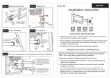
Mounting
1. Remove the fence and fence rails from your
table saw. Remove the left wing of your table
saw or the front wing of your shaper. The
front and rear fence rails can only extend 1''
past the left side of the machine table. They
will require trimming before reinstalling.
2. Attach the upper guide rail to the machine
through the extension wing mounting holes.
Use the cap screws and spacers supplied
and install the spacers between the machine
table and upper guide rail. NOTE: The slid-
ing table is supplied with two different size
Figure 3. Drilling the mounting holes.
Figure 2. Aligning the upper rail.
mounting cap screws,
3
⁄8''-16 x 2
3
⁄8'' and M10-
1.50 x 55mm. If your machine has a different
thread than listed here, you will need to
obtain bolts from your local hardware store.
Make sure the threaded portion is at least
2
3
⁄8'' long.
3. Adjust the upper guide rail
1
⁄8
'' below the sur-
face of your machine’s table. Measure from
the upper rail to the floor at both ends to
achieve parallelism. Tighten the cap screws
when the rail is properly adjusted. Figure 2.
4. To mount the lower guide rail bracket, refer
to the drill guide sheet on page 14 for prop-
er hole locations. Drill two pilot holes using a
1
⁄8'' drill bit then finish with a
3
⁄8'' drill bit.
Figure 3. Please note that Grizzly machines
are pre-drilled.
SECTION 3: INSTALLATION
Always wear safety
glasses throughout the
entire assembly process.
The use of a hand drill is
necessary and chips will
be propelled into the air
which may lead to seri-
ous personal injury.
Disconnect power to the
machine when perform-
ing any maintenance,
assembly or adjust-
ments. Failure to do this
may result in serious
personal injury.
!

-10- G4227 Sliding Table
Figure 4. Mounting lower guide rail bracket.
5. Install the lower guide rail bracket to the
stand/cabinet, using the two
5
⁄16''-18 x
3
⁄4'' hex
bolts, hex nuts and flat washers supplied.
Figure 4.
Figure 5. Mounting the lower rail.
6. Thread the mounting studs into the lower rail
approx.
1
⁄2''. Attach the lower rail to its mount-
ing bracket. Figure 5.
7. Adjust the lower rail so its centerline is
approximately even with the edge of the
upper guide rail bracket. Figure 6.
Figure 6. Lower rail alignment.
Figure 7. Mounting the bracket.
8. With the sliding table upside down, mount
the guide bearing bracket arm using the four
1
⁄4''-20 x
3
⁄4'' cap screws, flat washers and
lock washers provided. Figure 7. Lift up on
the bracket arm while tightening to ensure
the cap screws will be at the end of the slot.
If this detail is overlooked, the head of the
cap screws will not allow the fence to swing
to 45˚.

G4227 Sliding Table -11-
Figure 11. Lower pinch roller adjustment.
Figure 9. Front stop installation.
10. Slide the rubber ring onto the front rail and
install the front stop assembly. Figure 9.
11. Install the rear stop using the #10-24 x
3
⁄4''
Phillip head screw provided. Figure 10.
Figure 10. Rear stop installation.
12. Slightly loosen the lower front and rear pinch
roller nuts with a 14mm wrench. Now turn
their eccentric shafts with a 17mm wrench
until they are at their lowest position. Figure
11.
13. Prior to adjusting the upper eccentric
grooved rollers, it must be understood that
the grooved rollers need to remain in full
contact with the upper rail during the adjust-
ment process in order to achieve proper
adjustment. Figure 12.
Nut
Figure 8. Adjust lower guide bearing.
9. Slide the table mechanism onto the rails.
Adjust the lower bearing guide until it is cen-
tered on the lower guide rail as in Figure 8.
Please note: the upper grooved rollers can
be easily derailed at this point (see Figure
12).
Eccentric

-12- G4227 Sliding Table
Figure 12.
Figure 13. Roller adjustment.
15. Raise the pinch rollers back up and tighten
the nuts. Roll back the eccentric slightly if the
table travel is stiff.
16. Mount the fence by sliding the plastic T-nuts
into the bottom of the fence. Insert the short
stud into the hole closest to the machine
table, the longer stud with spacer goes
through the sliding mount. Figure 14. Install
the lock handles from below.
14. Now loosen the eccentric roller shaft nuts
slightly and rotate the eccentric shafts until
the sliding table is about
1
⁄16
'' above the
machine table. Tighten the nuts down and
recheck the sliding table height. Fine tune
the table height by turning the upper grooved
roller eccentric shafts without loosening the
nut. Figure 13.
Figure 14. Mounting the fence.
Figure 15. Adjusting the lower guide.
17. Set the sliding table fence so it extends to
the saw blade or shaper fence. Figure 15.
Loosen the lower bearing guide shaft nut
and rotate the eccentric shaft from below the
bearing until the end of the fence almost
touches the machine table. Retighten the
nut. NOTE: If the eccentric does not provide
sufficient travel, the threaded mounting studs
on the lower guide rail assembly can be
adjusted by turning the nuts on either side of
the bracket.

G4227 Sliding Table -13-
Figure 17. Installing fence stop.
Figure 19. Optional fence position.
Figure 18. Installing auxiliary handle.
20. Mount the auxiliary handle by removing the
stop bolt from the handle, slide the long por-
tion of the handle through the guiding hole at
the bottom/rear of the sliding table. Attach
the pinch bracket to the bottom/front of the
table using the lock handle with stud. Figure
18.
21. The fence can also be mounted at the rear of
the sliding table in the same manner as it
attaches in the front. Figure 20. Adjust the
fence perpendicular to the blade/fence by
loosening the setscrew and rotating the
eccentric bushing.
22. Remount your fence rails to your table saw
for ripping operations. It will be necessary to
cut the left ends of the front and rear rails so
they will fit with the sliding table top rail. A
hacksaw and file will do nicely. NOTE: On
saws with rail mounted switches, the switch
may need to be relocated to another conve-
nient location. For safety reasons, Do Not
mount the switch in a hard to reach location.
19. Next, apply the self adhesive scale in the top
front groove of the fence and install the
adjustable fence stop. Figure 17.
Setscrew
Eccentric bushing
Figure 16. Adjusting positive stop.
Stop bolt
18. Now, set the fence to 0˚ by placing a square
between the miter slot and the fence. The
stop bolt can be adjusted to ensure the fence
will return to 90˚ after it has been moved.
Figure 16.

-14- G4227 Sliding Table

G4227 Sliding Table -15-
The Model G4227 Sliding Table, when attached
to your table saw or shaper, allows you to easily
handle cumbersome material when crosscutting
or cross shaping. The sliding table fence safely
supports your work which is guided on rails and
ball-bearing rollers. The fence has a large bear-
ing surface and can be adjusted from any angle
between 90° and 45°. For repetitive cutting, the
fence also has a variable positioning stop block
that can be flipped out of the way when not need-
ed. The fence can also be adjusted out of the way
when ripping or doing standard shaping opera-
tions.
The Model G4227 Sliding Table replaces the
miter gauge function. To crosscut or cross shape:
1. Ensure that the Model G4227 is properly
adjusted on your machine.
2. Move the rip fence completely out of the
way.
3. Set the angle of the sliding table fence to the
desired angle of cut.
4. Without turning on the table saw or shaper,
slide the table and fence in the direction of
the cut. Adjust the fence toward or away
from the blade or cutter so that your work-
piece will be adequately supported near the
blade or cutter, but will not touch the blade or
cutter. If full support of the workpiece is
desired to minimize tear out, an auxiliary
wood fence that extends out past the fence
can be mounted to the sliding table fence.
5. Place your workpiece on the sliding table
and against the fence at the desired distance
from the blade or cutter.
General Use
Before you put your Sliding Table into use, let’s
give it a quick inspection.
1. Are all fasteners tight?
2. Has the sliding table been adjusted accord-
ing to the guidelines set forth in this manual?
3. Have you read all safety rules?
Test Run
6. Ensure that all safety rules are observed.
Turn the table saw or shaper on and guide
the sliding table through the cut with one
hand on the sliding table handle and the
other hand securing the workpiece against
the fence.
7. Once the cut has been made, turn the table
saw or shaper off.
Always wear safety
glasses while operating
machine. Chips will be
propelled into the air
which may lead to seri-
ous personal injury.
SECTION 4: OPERATIONS

-16- G4227 Sliding Table
SECTION 5: MAINTENANCE
Lubrication
Your sliding table is equipped with shielded and
pre-lubricated ball bearings that require no lubri-
cation for the life of the bearings. All bearings are
common sizes and are readily available from a
local bearing supply house or through the Grizzly
Industrial parts department.
Make a habit of inspecting your sliding table each
time you use it. Check for loose bolts. Vacuuming
the sliding table clean after every use ensures
that sawdust won't trap moisture against bare
metal surfaces. Clean the upper rollers, lower
rollers and the guide rails with steel wool about
every 6 months to prevent excessive pitch build
up.
General

G4227 Sliding Table -17-
The following pages contain a parts diagram, parts
list and Warranty/Return information for your
Model G4227 Sliding Table.
If you need parts or help in assembling your slid-
ing table, or if you need operational information,
we encourage you to call our Service
Department. Our trained service technicians will
be glad to help you.
If you have comments dealing specifically with
this manual, please write to our Bellingham,
Washington location using the address in
Section 3: Introduction. The specifications,
drawings, and photographs illustrated in this
manual represent the Model G4227 as supplied
when the manual was prepared. However, due to
Grizzly’s policy of continuous improvement,
changes may be made at any time with no oblig-
ation on the part of Grizzly. Whenever possible,
though, we send manual updates to all owners of
a particular tool or machine. Should you receive
one, add the new information to this manual and
keep it for reference.
We have included some important safety mea-
sures that are essential to this machine’s opera-
tion. While most safety measures are generally
universal, Grizzly reminds you that each work-
shop is different and safety rules should be con-
sidered as they apply to your specific situation.
We recommend you keep a copy of our current
catalog for complete information regarding
Grizzly's warranty and return policy. If you need
additional technical information relating to this
machine, or if you need general assistance or
replacement parts, please contact the appropri-
ate regional Service Department listed in the
Section 3: Introduction.
Additional information sources are necessary to
realize the full potential of this sliding table. Trade
journals, woodworking magazines, and the
shelves of your local library are good places to
start. Knowledge and caution are vital compo-
nents of successful operation.
As with all table saws and shapers, there is
the potential for danger when using the
Model G4227 Sliding Table. Use the table saw
or shaper with respect and caution to lessen
the possibility of operator injury or mechani-
cal damage. If normal safety precautions are
overlooked or ignored, serious injury to the
operator or others in the area is possible.
SECTION 6: CLOSURE
The Model G4227 was specifically designed
for use with table saws and shapers. DO
NOT MODIFY AND/OR USE THIS ACCESSO-
RY FOR ANY OTHER PURPOSE.
Modifications or improper use of this unit
will void the warranty. If you are confused
about any aspect of this accessory, DO NOT
use it until all your questions have been
answered. Serious personal injury may
occur.
Commentary
Operating this equipment has the potential
for flying debris to cause eye injury. Always
wear safety glasses or goggles when oper-
ating equipment. Everyday glasses or read-
ing glasses only have impact resistant lens-
es, they are not safety glasses. Be certain
the safety glasses you wear meet the appro-
priate standards of the American National
Standards Institute (ANSI).

-18- G4227 Sliding Table
Design Type..........................................................................Rails with Ball Bearing Rollers
Overall Dimensions:
Table Size ....................................................................................................15
3
⁄4" x 22"
Fence Size ................................................................................................2" x 2" x 42"
Fence Positions ......................................................................................Front 0˚ - 45˚
................................................................................................Back 0˚
Typical Cross Cut Capacity ......................................................................................26"
Total Travel ..............................................................................................................48"
Weight (Net) ........................................................................................................85 lbs.
Weight (Shipping)................................................................................................90 lbs.
Construction
Table ..................................................................................................Composite Wood
Body Assembly......................................................................................................Steel
Fence ............................................................................................................Aluminum
Mounting Requirements for Table saws: (G1023S, G1023Z, G1023ZX)
Remove Left Extension Wing
Trim Fence Rails Left of the Blade
Relocate the Switch
Drill Mounting Holes in the Cabinet
Mounting Requirements for Shapers: (G1035, G1026)
Remove Table Wing (If Applicable)
Drill Holes in Cabinet
Specifications, while deemed accurate, are not guaranteed.
Customer Service #: (570) 546-9663 • To Order Call: (800) 523-4777 • Fax #: (800) 438-5901
GRIZZLY MODEL G4227 SLIDING TABLE
MACHINE DATA
SHEET

G4227 Sliding Table -19-
/