Page is loading ...

RWF...
RWF
INS-RWF_0322
OWNER’S MANUAL
WALL FAN HEATER
THIS UNIT COMPLIES
WITH CSA STANDARDS
THANK YOU FOR YOUR PURCHASE!
QUESTION? PROBLEM? CONTACT STELPRO CUSTOMER SERVICE.
WWW.STELPRO.COM
1-844-STELPRO

2
Before installing and using this product, you must read and understand
these instructions and keep them for future reference. If the installer and
the user do not follow these instructions, the manufacturer cannot be held
liable in any way and the warranty will be null and void.
This product must be installed by a qualied person and connected by a
certied electrician, according to the electrical and building codes eective
in your region.
The following instructions must be adhered to in order to avoid personal
injuries or property damages, serious injuries and potentially fatal electric
shocks.
Protect the heating unit with the appropriate circuit breaker or fuse, in ac-
cordance with the nameplate.
Make sure the line voltage (volts) is consistent with that indicated on the
unit’s nameplate.
This unit must be grounded.
Switch o the power at the circuit breaker or fuse before installing, repair-
ing and cleaning the unit.
INTENDED USE
Make sure the unit is appropriate for the intended use (if needed, refer to
the product catalog or a representative).
RECOMMENDED HEATING CAPACITY: 1,25 W per ft3 (0.03 m3).
This corresponds to 10 W per ft2 (0.09 m²) based on a standard ceiling
height of 8 ft (2.44 m). The recommended capacity is usually sucient for
normal heating needs. Please note that the insulation quality of walls and
windows are some of the factors that inuence heat losses, which modify
the required capacity to heat a room. If needed, speak with a specialist
(industrial and commercial buildings) who will be able to calculate these
heat losses and optimize the required capacity or consult the “Calculation
Tools/Heating Calculator” section of the Stelpro Design website. To heat
a large room and increase its comfort, you should install multiple units
instead of one, for instance, 2 x 1000 W rather than 1 x 2000 W.
If the unit capacity is insucient for the size of the room, it will be in opera-
tion continuously, and may become defective earlier and turn yellow.
POSITION
Do not install the unit where objects or pieces of furniture could be heat
damaged.
Respectez les distances et les positions mentionnées dans la section
d’installation de ce guide.
If the installer or the user modies the unit, they will be held responsible
for any damage resulting from this modication, and the CSA certication
could be void.
This unit must not come into contact with a water source and must be
protected from splashes (e.g., splashes from a sink or shower). Do not use
it if any part has been immersed. Moreover, do not turn it on or o when
standing in water or if your hands are wet.
When mounting the unit, ensure that the anchorage can support the total
weight of the unit plus the weight of the mounting brackets.
When cutting or drilling a wall to install the unit, be careful not to damage
hidden electrical wiring and other utilities.
Do not install this product on walls made of synthetic materials such as,
but not limited to, carpet and upholstery.
RISK OF FIRE, ELECTRIC SHOCK,
BODILY INJURY AND DAMAGE
When starting up the unit for the rst time or after a long period, it is nor-
mal that it produces some temporary odours and a thin whitish smoke.
Because this unit is hot when in use, it may pose risks even in normal
operation. Therefore, be careful and responsible when using it. To avoid
burns, do not let bare skin touch hot surfaces. The unit must cool down for
few minutes since it will stay warm for some time after shut down.
Leave at least 8 inches (20.3 cm) of free space between the unit and any
adjacent surfaces (walls and oors). Moreover, do not allow objects or
furniture such as, but not limited to, blankets, towels, bedding, laundry
baskets, clothing, papers, etc. to come in contact with the unit and keep
them at least 12 inches (30.5 cm) away from the unit, as they may ignite
more easily than adjacent surfaces. Also, some materials are more sensi-
tive to heat than others, so make sure that the materials near your unit can
withstand the heat it gives o.
Do not install on a wall behind a door.
To prevent a possible re, do not block air intakes or exhaust in any matter.
Do not insert or allow foreign objects to enter any ventilation or exhaust
opening as this may cause an electric shock or re, or damage the heater.
This unit has hot and arcing or sparking parts inside. It is not designed
to be used or stored in wet areas or areas containing ammable liquids,
combustible materials or corrosive, abrasive, chemical, explosive and
ammable substances such as, but not limited to, paint, gasoline, chlorine,
sawdust and cleaning products.
MAINTENANCE
Some areas are dustier than others. Thus, it is the user’s res ponsibility to
evaluate if the unit must be cleaned based on the amount of dirt accumu-
lated on and inside air vents. Accumulated dirt can lead to a component
malfunction or give a yellowish colour to the unit. Failure to install and
maintain the unit in accordance with these instructions poses a re hasard.
Thermal protection activation indicates that the unit has been subjected to
abnormal operating conditions. If the thermal protection remains activated
it is recommended that a qualied electrician or a certied repair centre
examine the unit in order to make sure it is not damaged. (Refer to the
limited warranty.)
If the unit is damaged or defective, discontinue use, cut o power supply
at circuit breaker or fuse and have it repaired at a certied repair centre.
Make sure that the electrical connections are secure and that they have
been made properly. Pull on each wire to ensure that there is no slack in
the connector or terminal block. Failure to do so could result in a re.
If adding an option to the unit, make sure it is approved by Stelpro. This
will ensure that it has been tested in accordance with the established
safety rules and that proper installation has been provided for it in the unit.
IMPORTANT INSTRUCTIONS
SAVE THESE INSTRUCTIONS

3
XXX
VOLT
WHAT IS IN THE BOX
INSTALLING THE FAN HEATER
TO ENSURE A SAFE AND EASY INSTALLATION, TAKE A FEW MINUTES TO READ THIS INSTALLATION GUIDE.
Wall fan heater
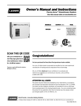
SPECIFICATIONS AND NAMEPLATE
Volt 120, 208, 240/208, 277, 347
Watts 500 à 2000W
Weight 6 lb / 2,7 kg
Depth 3-3/16” / 80 mm
Width 8-11/16” / 220 mm
Heigth 17-1/8” / 435 mm
TOOLS REQUIRED
• Level
• Wire stripper
• Flat screwdriver
• Phillips screwdriver
• Tape measure
• Stud nder
• Wire clamp
FOR RECESSED INSTALLATION
• Tool to cut drywall or gypsum
board
• 2 Screws 1-1/2" (38 mm) with
a 1/4" (6.5 mm) diameter
head minimum, suitable for
securing the back box directly
to a stud.
FOR SURFACE INSTALLATION
• Surface adapter
(sold separately)
• 4 screws with appropriate
anchorage for the installation
surface
• 4 gypsum screws
The nameplate is
located at the bottom
of the unit’s housing.
2 twist-on
wire connectors
CONTROLLING THE FAN HEATER
Depending on the model chosen, refer to the table below for information on how to control the fan heater.
RWFxxxx This model can be controlled with a compatible wall-mounted thermostat*
to adjust the room’s temperature setpoint. ---
RWFxxxxT
This model can be controlled by means of its mechanical thermostat.
• The room temperature setpoint is controlled by a knob that’s graduated
from 0 to 5. The 1 represents the minimum heating degree, while the 5
represents the maximum heating degree.
RWFxxxxC24 • This model can be controlled with a thermostat or a 24V control.
*Electronic thermostat with fan heater mode or mechanical thermostat

4
1DETERMINING THE FAN HEATER’S
POSITION AND TYPE OF
INSTALLATION
VERTICAL INSTALLATION
HORIZONTAL INSTALLATION
SURFACE ADAPTER
(SOLD SEPARATELY)
RECESSED INSTALLATION
SURFACE INSTALLATION
2WHERE TO INSTALL YOUR FAN HEATER
8 IN.
(20.3 CM)
MIN.
8 IN.
(20.3 CM)
MIN.
12 IN.
(30.5 CM)
MIN.
ATTENTION: To avoid any risk of
overheating, leave a clearance of at least
12 in. (30.5 cm) in front of the fan heater,
8 in. (20.3 cm) on either side of it and at
least 8 in. (15 cm) from the ground.
Do not install the heater on a wall behind
a door.
No objects or furniture such as, but not
limited to, blankets, towels, a bed, a laundry
basket, clothing, papers, etc., should come
into contact with fan heater. Keep these
items at least 12 in. (30.5 cm) away from it.
It is not designed to be used or stored in
wet areas or areas containing ammable
liquids, combustible materials or corrosive,
abrasive, chemical, explosive and am-
mable substances such as, but not limited
to, paint, gasoline, chlorine, sawdust and
cleaning products.
Avoid installing in an exterior wall as this
decreases the wall’s insulation.

5
ON OFF
A
1. To protect yourself from the risk of electric shock, turn off
the power supply to the lead wires from the electrical panel.
3CUTTING THE POWER SUPPLY
WARNING: This product must be installed by a certied electrician according to the electrical and building codes
eective in your region.
1. Unscrew the two (2) screws holding the grille to
remove it.
4PREPARING THE FAN HEATER
2. Remove the mechanical housing by unscrewing the
four (4) screws.
3. Depending on the location of the power cable, drill a
knockout into the back housing to allow the cable to
pass through.
4. Place the wire clamp [A] in the recessed hole. Insert
the power cable through the wire clamp and secure
it in place.
* Wire clamp not included

6
A
A
B
B
1. Using the stud nder, locate the studs.
Also, consider the location of pipes,
wires or other components in the wall
that may be damaged.
2. Measure the space required according
to the diagram shown opposite.
3. Make an opening according to the
desired installation direction.
4. Route the power cable out of the wall. Al-
low at least 6" (15 cm) of cable inside
the enclosure for easy connection to
the unit’s wires.
5PREPARING THE SURFACE FOR FLUSH MOUNTING
14 5/8 IN.
(37.2 CM)
6 1/2 IN.
(16.5 CM)
9.5 IN. (24.1 CM)
MIN.
9.5 IN. (24.1 CM)
MIN.
14 5/8 IN.
(37.2 CM)
6 1/2 IN.
(16.5 CM)
RECESSED INSTALLATION
RECESSED INSTALLATION
1. Insert the fan heater’s back housing
into the opening you’ve made in the
wall, making sure that it’s level.
6MOUNTING THE BACK HOUSING TO THE WALL
2. Screw* the enclosure into place on the wall studs using
two (2) mounting holes [B], depending on your situation.
NOTE: If the wall hasn’t been nished
yet, be sure to position the enclosure
at the correct depth so that it will be
supported on the surface when the
work is complete. The shoulder of
the housing [A] must remain on the
surface of the nished wall.
TOP VIEW
FINISHING
* Screws not included.

7
L1
L1
L2/N
L2/N
GND
GND
AA
A A
AVEC MANCHONSANS MANCHON
8 IN (20.3 CM) MIN 8 IN (20.3 CM) MIN
SURFACE INSTALLATION
1. Route the power cable out of the wall. Allow at least 6" (15 cm) of cable
inside the enclosure for easy connection to the unit’s wires.
2. Lean the enclosure against the wall, level it, and then screw four (4) wood
screws (not supplied) into the holes provided [A]. At least two screws
should be xed in a stud.
WARNING: Use only copper or aluminum wire that
can withstand a temperature of 90°C (194°F).
NOTE: Make sure that the supply voltage (volts)
corresponds to that indicated on the nameplate
(see diagram p.3)
• A 120V powered installation has a black and white
power cable.
• A 240V powered installation has a red and black
power cable.
1. If necessary, strip the power cable wires with a wire
stripper.
2. Connect the fan heater and power supply wires with
the connection caps provided according to the con-
nection diagram. Tighten the caps rmly on the wires
to ensure that the connection is secure.
3. Connect the ground wire using the green ground screw
on the side of the back housing.
4. Store all wires in the bottom of the back housing.
7CONNECTING THE
ELECTRICAL WIRES
ELECTRICAL DIAGRAM OF INSTALLATION WITH AND WITHOUT THERMOSTAT
ELECTRICAL DIAGRAM OF INSTALLATION WITH A 24 VOLT THERMOSTAT
* Thermostat
sold separately
MOTOR
SINGLE POLE
BUILT-IN
THERMOSTAT*
DOUBLE POLE
BUILT-IN
THERMOSTAT*
THERMAL
PROTECTION
ELEMENT
ELEMENT
MOTOR
24 VOLT
EXTERNAL
THERMOSTAT
THERMAL
PROTECTION
ELEMENT
ELEMENT
RELAY

8
A
A
A
B
8ATTACH THE MECHANICAL HOUSING TO THE REAR HOUSING
1. Reinstall the mechanical housing by screwing
back the four (4) screws previously removed.
2. Insert the sleeve around the frame using the guides
at the bottom of the frame [A] and screw it to the wall
using the four (4) screws (not supplied) in the semi-
circular cut-outs provided.
SURFACE INSTALLATION
IMPORTANT: Pay
attention to the
direction of the
grille. The opening
(A) must always
face the fan blades
and the opening
(B) the hot air
outlet. If the grille is
installed the wrong
way round, the unit
will stop working.
1. Restore the power supply to the fan
heater and make sure the unit works
by increasing the temperature set-
ting until the unit starts to heat up.
Refer to section Controlling the fan
heater, page 3.
10 RESTORING THE
POWER SUPPLY
9ATTACHING THE FRONT PANEL
1. Attach the grilled front panel with the two (2) screws once the wall is
nished.
WARNING: If you are using a
wall-mounted electronic ther-
mostat, you must switch it to
fan heater mode as soon as you
restore the electrical power. If the
thermostat remains in baseboard
mode, the fan heater will operate
intermittently and may overheat.
WARNING: Before using your fan heater, make sure that it has been installed by a certied electrician in accordance
with the electrical and building codes in your area.
Do not operate the unit without the front panel installed.

9
WWW.STELPRO.COM
1-844-STELPRO
The following table outlines the most common issues and alerts you could
experience with your fan heater.
If your problem is not listed in the table below or the proposed solution
does not solve the problem, turn the power off and contact our customer
service team.
PROBLEM/ALERT POSSIBLE CAUSE AND SOLUTION
The fan heater is not operational after
installation.
• Make sure the temperature setpoint is not too low.
• Check whether the fan heater’s wiring is correctly connected. See Connecting the electrical
wires, page 7
• Make sure that the circuit breaker corresponding to the heating system in the electrical panel
is closed (ON).
• If the problem persists, the thermostat may be defective. Contact Stelpro Customer Service.
The breaker goes off
when the fan heater starts.
• Check whether the fan heater’s wiring is correctly connected. See Connecting the electrical
wires, page 7.
• Make sure the voltage supplied is adequate (see the nameplate).
• Make sure the circuit breaker or fuse is adequate for the requested power.
The temperature setpoint
is never reached or the fan heater is
operating continuously.
• Make sure the voltage supplied is adequate (see the nameplate).
• Make sure the unit is powerful enough for the size of the room.
• The fan heater is overheating, and the thermal protection has been triggered. Make sure the
unit’s air inlet and air outlet are not obstructed. Once the cause of overheating is eliminated,
the unit will resume operating after a few minutes.
• If none of the solutions above work, one or more of the heating elements may be defective.
ContactStelpro Customer Service.
The ambient temperature
is too high.
• Make sure the temperature setpoint is adequate.
• If the problem persists, the thermostat may be defective. Contact Stelpro Customer Service.
Heating is not operational.
• The fan heater is overheating, and the thermal protection has been triggered. Make sure the
unit’s air inlet and air outlet are not obstructed. Once the cause of overheating is eliminated,
the unit will resume operating after a few minutes.
• Make sure the temperature setpoint is not too low.
• Check whether the fan heater’s wiring is correctly connected. See Connecting the electrical
wires, page 7.
• If the problem persists, the thermostat or one of the heating elements may be defective.
Contact Stelpro Customer Service.
Heating stops, but ventilation
continues. • An internal component may be defective. Please contact Stelpro Customer Service.
With a wall thermostat: thefan heater
turns on and off frequently. • Make sure the wall thermostat is in fan mode.
With a wall-mounted thermostat:
the display switches off.
• The fan heater is overheating, and the thermal protection has been triggered. Make sure the
unit’s air inlet and air outlet are not obstructed. Once the cause of overheating is eliminated,
the unit will resume operating after a few minutes.
• If the problem persists, an internal component may be defective. Contact Stelpro Customer
Service.
The elements are powered (elements
are emitting a red glow), but the fan
isn’t running.
• The motor is defective. Switch off the unit and contact Stelpro Customer Service.
TROUBLESHOOTING THE FAN HEATER

10
STELPRO DESIGN INC.
Saint-Bruno-de-Montarville, Québec, Canada, J3V 6L7
This limited warranty is offered by STELPRO Design inc. (“STELPRO”) and applies to
the following product made by STELPRO: RWF model. Please read this limited war-
ranty carefully. Subject to the terms of this warranty, STELPRO warrants its products
and their components against defects in workmanship and/or materials for the fol-
lowing periods from the date of purchase: 5years. This warranty applies only to the
original purchaser; it is non-transferable and cannot be extended.
CLAIM PROCEDURE
If at any time during the warranty period the unit becomes defective, you must cut off
the power supply at the main electrical panel and contact 1) your installer or distributor,
2) your service center or 3) STELPRO’s customer service department. In all cases, you
must have a copy of the invoice and provide the information written on the product
nameplate. STELPRO reserves the right to examine or to ask one of its representatives
to examine the product itself or any part of it before honoring the warranty. STELPRO
reserves the right to replace the entire unit, refund its purchase price or repair a defec-
tive part. Please note that repairs made within the warranty period must be authorized
in advance in writing by STELPRO and carried out by persons authorized by STELPRO.
Before returning a product to STELPRO, you must have a STELPRO authorization num-
ber (RMA). To obtain it, call the customer service department at: 1-844-STELPRO. The
authorization number must be clearly written on the parcel or it will be refused.
CONDITIONS, EXCLUSIONS AND DISCLAIMER OF LIABILITY
This warranty is exclusive and in lieu of all other representations and warranties (except
of title), expressed or implied, and STELPRO expressly disclaims and excludes any im-
plied warranty of merchantability or implied warranty of tness for a particular purpose.
STELPRO’s liability with respect to products is limited as provided above. STELPRO
shall not be subject to any other obligations or liabilities whatsoever, whether based on
contract, tort or other theories of law, with respect to goods or services furnished by it,
or any undertakings, acts or omissions relating thereto. Without limiting the generality
of the foregoing, STELPRO expressly disclaims any liability for property or personal
injury damages, penalties, special or punitive damages, damages for lost prots, loss
of use of equipment, cost of capital, cost of substitute products, facilities or services,
shutdowns, slowdowns, or for other types of economic loss or for claims of a dealer’s
customers or any third party for such damages. STELPRO specically disclaims all
consequential, incidental and contingent damages whatsoever.
This warranty does not cover any damages or failures resulting from: 1) a faulty installa-
tion or improper storage; 2) an abusive or abnormal use, lack of maintenance, improper
maintenance (other than that prescribed by STELPRO) or a use other than that for
which the unit was designed; 3) a natural disaster or an event out of STELPRO’s control,
including, but not limited to, hurricanes, tornadoes, earthquakes, terrorist attacks, wars,
overvoltage, ooding, water damages, etc. This warranty does not cover any accidental
or intentional losses or damages nor does it cover damages caused by negligence of
the user or owner of the product. Moreover, it does not cover the cost of disconnection,
transport, and installation.
The warranty is limited to the repair or the replacement of the unit or the refund of its
purchase price, at the discretion of STELPRO. Any parts replaced or repaired within
the warranty period with the written authorization of STELPRO will be warranted for the
remainder of the original warranty period. This warranty will be considered null and void
and STELPRO will have the right to refuse any claims if products have been altered
without the written authorization of STELPRO and if the nameplate numbers have been
removed or modied. This warranty does not cover scratches, dents, corrosion or dis-
coloration caused by excessive heat, chemical cleaning products and abrasive agents.
It does not cover any damage that occurred during the shipping.
Some states and provinces do not allow the exclusion or limitation of incidental or con-
sequential damages and some of them do not allow limitations on how long an implied
warranty lasts, so these exclusions or limitations may not apply to you. This warranty
gives you specic legal rights and you may have other rights which vary from state to
state or from province to province.
STELPRO LIMITED WARRANTY
MAINTAINING THE FAN HEATER
Use a soft cloth to remove dust from the fan heater. If it’s
in a very dusty location, use the dusting brush of a vacuum
cleaner. If necessary, vacuum the inside of the unit.
Dust the front panel with a soft cloth and clean it with a damp
cloth only. If you use cleaning products, they could cause the
heater to yellow.
To avoid damaging the unit’s coating, never use:
• A brush or metal scrubbing pad
• Abrasive cleaning products
• Chlorine
• Hydrochloric acid-based products such as bleach
• Any other cleaning products that bear the following
symbols:
NOTE: For the warranty to be valid, the fan heater’s air inlet and outlet must be cleaned regularly.
Over time, cigarette smoke may cause the outlet grill to yellow. The best way to prevent yellowing is to clean
the unit regularly.
WARNING: Cut o the power at the breaker or fuse before cleaning the unit. High voltage and the risk of electric
shock are present in the unit even if the thermostat is set to o. Therefore, you can receive an electrical shock as
long as the unit is under power.
/