Page is loading ...

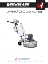
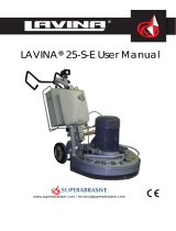
LAVINA® 25-S User Manual
Tech Support Line: 800-987-8403 | www.superabrasive.com | info@superabrasive.us

Superabrasive UserManual OriginalLanguageLavina®25‐S/Lavina®25‐S‐HV 8/2014
2

Superabrasive UserManual OriginalLanguageLavina®25‐S/Lavina®25‐S‐HV 8/2014
3
WARRANTY AND RETURNS
WARRANTY POLICY FOR LAVINA® S MACHINES
A warranty card must be submitted to Superabrasive within 30 days of purchase in order for the foregoing warranty to
apply.
You can either mail a hard copy of the warranty card or submit it electronically - see page 2.
Superabrasive warrants, from the time of delivery and receipt by the original customer, new and unused products
sold by
Superabrasive or Superabrasive-appointed distributors or dealers. Goods shall be free from defects in
materials and
workmanship. Superabrasive or a Superabrasive-appointed repair facility shall either replace or
repair any defects in the
Goods resulting from faulty design, materials, or workmanship. Products repaired or
replaced during the warranty period
shall be covered by the foregoing warranty for the remainder of the original
warranty period, or ninety (90) days from date
of the repair or shipment of the replacement, whichever is longer.
Spare parts for repair will be either new or equivalent to
new.
Warranty period shall be 2 years from the time of delivery and receipt by the original customer, or 600 operating
hours on
the machine - whichever occurs first. Superabrasive will cover the shipping charges for the transportation
of the machine to
Superabrasive (or an approved repair facility) and back to the customer (within the contiguous 48
United States) in the event
that the damage occurs and is reported within the first 90 days or 200 operating hours -
whichever occurs first. Shipping
charges, if covered by Superabrasive, must be agreed upon in advance and
approved by Superabrasive. Thereafter, the
customer will have to cover the shipping charges to Superabrasive and
back. Superabrasive will not warranty Goods after a
period of 2 years from the time of delivery and receipt by the
original customer, or 600 operating hours on the machine -
whichever occurs first.
Superabrasive shall not be liable for any defects that are caused by circumstances that occur after the Goods
have been
delivered and whilst the Goods are in the possession of the purchaser. Furthermore, the warranty
does not include normal
wear and tear or deterioration. Wear parts are not warranted. Superabrasive is not liable
for defects arising out of use of
non-OEM parts.
The Warranty is void if the purchaser has not followed the maintenance plan stipulated by the machine’s manual
and
warranty card. The warranty is void if the purchaser repairs said Goods himself, or if repairs are conducted by a
repair facility
that is not approved by Superabrasive. Superabrasive’s liability does not cover defects which are
caused by faulty
maintenance, incorrect operation, faulty repair by the purchaser, or by alterations conducted
without Superabrasive’s prior
written consent. The same applies to any alterations of the Goods or services
performed by another party other than
Superabrasive, a Superabrasive-appointed distributor, or a Superabrasive-
approved repair facility. The warranty is not
applicable on a defect that arises due to tools or parts that are not
original to Superabrasive. Replaced defective parts shall
be placed at Superabrasive’s disposal and shall become
property of Superabrasive. If such defective parts are replaced
within the warranty period, the shipping charges will be covered by Superabrasive. In warranty complaint cases,
when no
defects are found for which Superabrasive is liable, Superabrasive shall be entitled to compensation for
the labor, material
cost, and shipping charges, incurred by Superabrasive as as a result of the complaint.
The warranty herein is non-transferable, and only applies to the original owner or purchaser of the machine.
RETURN POLICY FOR LAVINA® S MACHINES
The Lavina® S machines may be returned, subject to the following terms:
In no case, a machine is to be returned to Superabrasive Inc. for credit or repair without prior authorization.
Please contact
Superabrasive Inc. or your local distributor for an authorization and issuance of a return
authorization number. This number
along with the serial number of the machine must be included on all packages
and correspondence. Machines returned
without prior authorization will remain property of the sender and
Superabrasive Inc. will not be responsible for them. No
machines will be credited after 90 days from the date of
invoice.
All returns must be shipped freight prepaid. Returned machines may be exchanged for other equipment or parts of
equal
dollar value. If machines are not exchanged, they are subject to a fifteen percent (15%) restocking fee.

Superabrasive UserManual OriginalLanguageLavina®25‐S/Lavina®25‐S‐HV 8/2014
4
WARRANTYANDRETURNS
3
1.GENERALINFORMATION
Preface5
Manufacturer 5
GeneralDescription 5
MachineCharacteristics 5
MainDesign 5
EnvironmentalConditions 5
ElectricalConnection 5
VacuumConnection 6
TechnicalData 6
Vibrations6
SonorousEmissions 6
LabelData6
CustomerService 6
2.SAFETYINSTRUCTIONS
RecommendedUse 6
ProhibitedUse 6
PreparationforWork 6
ProtectionDevices 7
ArrestFunctions 7
SafeUse7
ResidualRisks 7
BeforeYouBegin 7
OperatingMachine 7
AfterWorkisCompleted 7
TheWorkArea 7
PersonalProtectiveEquipment(Ppe) 7
Operator7
3.HANDLINGANDTRANSPORTATION
PreparingtheMachineforTransportation 8
LifttheMachinefromWorkingtoToolMounting
Position8
Lifting8
AdjustingtheHandle 8
Storage9
4.OPERATION
PreliminaryControls 9
WaterFlowControlUnit 9
AdjustingandMountingTools 9
FrameBlocking(U‐Joint) 9
ControlBoard 10
StartingtheMachine 10
OperatingtheMachine 10
StoppingMachine 10
Alarm10
5.TOOLSANDACCESSORIES
Weights11
ToolHolderKey 11
FoamPlate11
SecurityPlateforQuickchangePads 11
6.POPULARTOOLS 12
7.EXPLODEDVIEW
GeneralExplodedView(Fig.7.1) 13
TopCoverExplodedView1(Fig.7.2) 13
PlanetaryDriveExplodedView(Fig.7.3) 13
TopCoverExplodedView2(Fig.7.4) 13
BottomCoverExplodedView1(Fig.7.5) 14
BottomCoverExplodedView2(Fig.7.6) 14
PulleyUnitsExplodedView(Fig.7.7) 14
CarriageExplodedView(Fig.7.8) 14
ToolHolderExplodedView(Fig.7.9) 14
8.MAINTENANCEANDINSPECTION
Cleaning15
CheckDaily 15
Checkandreplaceafterthefirst15WorkingHours 15
CheckEvery200WorkingHours 15
CheckEvery400WorkingHours 15
Vacuum15
WaterLeaks 15
MechanicalParts 15
ElectricalSystem 15
ElectricalSchemes200‐240Volt 16
ElectricalSchemes380‐480Volt 17
9.TROUBLESHOOTING
IndexofProblemsandSolutions
9.1ReplacingPowerCordandPlugs 18
9.2DismountingandMountingToolHoldertochangebuffers
andspiders,changingV‐RingsandFelt‐Rings18
9.3TensioningandReplacethePlanetaryBelt 19
9.4TensioningUsedPlanetaryBelt 19
9.5MountingandTensioninganewPlanetaryBelt 19
9.6CheckingtheTensionoftheBelt 20
9.7ReplacingofthePulleyUnits 21
9.8MountingtheBelt 22
9.9MotorConnection 22
9.9FaultDiagnosisInverterYASKAWAV1000 23
10.DISPOSAL
Disposal25
11.MANUFACTURER’SCONTACTS
Manufacturer’scontract 25
12.SPAREPARTS
1.GeneralParts/formachinesproducedbeforeJan.12014/26
1.GeneralParts/formachinesproducedafterJan.12014/26
2.TopCoverParts1/formachinesproducedbeforeJan.12014/27
2.TopCoverParts1/formachinesproducedafterJan.12014/27
3.TopCoverParts2 28
4.PlanetaryDriveParts 28
5.GuardParts 28
6.BottomCoverParts1 29
7.BottomCoverParts2 29
8.PulleyUnitsParts 30
8a.PulleyUnitAssembly 30
8b.DrivingPulleyUnit 30
9.WaterSupplyParts/formachinesproducedbeforeJan.12014/30
9.WaterSupplyParts/formachinesproducedafterJan.12014/30
10.ToolHolderParts 31
11.CarriageParts/formachinesproducedbeforeJan.12014/31
11.CarriageParts/formachinesproducedafterJan.12014/32
12.ControlBoxParts200‐240Volt 33
13.ControlBoxParts380‐480Volt 34

Superabrasive UserManual OriginalLanguageLavina®25‐S/Lavina®25‐S‐HV 8/2014
5
1.GENERALINFORMATION
Thisowner’smanualisintendedfortheoperatoroftheLavina®Smachine,theservicingtechnicianaswellasforanyoneinvolved
withoperatingorservicingthemachine.Werecommendthatyoureadtheinstructionsverycarefullyandfollowthem
strictly.Themanualincludesinformationaboutassembling,using,handling,adjustingandmaintainingyourLavina®Sfloor
grindingandpolishingmachine.
MANUFACTURER
Superabrasivewasfoundedin1987,asamanufacturerofhighqualitydiamondtoolsforthestoneandconcreteindustry.Today,
Superabrasiveisoneoftheworld’sleadingcompaniesintheproductionofdiamondtoolsandfloorgrindingmachinery.At
Superabrasive,westrivetodelivertheverybestsolutionstoourcustomers,andenablethemtoworkmoreefficiently.
GENERALDESCRIPTION
TheLavina®Smachineisintendedforgrinding,polishingandbuffingconcrete,marble,granite,limestone,andterrazzosurfaces
withdiamondtools.
TheLavina®Smachineisathree‐discmachine,whichcanbeuseddryaswellaswet.
Forbestresults,useonlytoolsmanufacturedorrecommendedbySuperabrasiveanditsdistributors.Additionally,themachine
couldbeusedforgrindingwoodfloorsurfaces.
TheLavina®Smachineismanufacturedandfittedfortheabove‐mentionedapplicationsonly!Everyother
usemaypossessriskstothepersonsinvolved.
MACHINECHARACTERISTICS
TheLavina®Smachineismadeoftwomaincomponentsections:
MAINDESIGN
Thetwomaincomponentsections,arethecarriageandmainhead.
Thehandle(Fig.1.2)ontheframeisadjustableinheightandallowstheoperatortoworkin
acorrectandsafeworkingposture.
Thehalogenspotlight(Fig.1.2)enablestheoperatortoworkindarker
areas.
Existinglightingsystemdoesnotreplaceadequateoverheadlighting.
Aframe(U‐jointtechnology)ontopofthemotorbaseallowsthemainheadtomovetoall
sidesanditgivesmoregrindingcapacity.
Thecontrolsarepositionedontopoftheelectricalbox(fig.1.3)
Theelectricalbox(fig.1.3)containstheelectricswitchingdevicesandtheinverter.
Themainfeedingcableisconnectedwithaplugandsocketontop.Themotorfeeding
cableispluggedintothesocketlocatedonthebottomofthebox.
Thetankisontheoppositesideoftheframe,sothattheweightofthe
waterhasnoinfluenceontheoperationofthemachine.Theframeweight,ontheother
hand,isfullyabsorbedbythedrivingwheels.Anelectricpumpspraysthewaterthrougha
frontsprayerorinternal.
Themotorismountedonthebaseplateandisdrivingthethreeheadswithabeltsystem.
Theplanetaryheadisdrivenbyasecondflatbelt.
ENVIRONMENTALCONDITIONS
ThetemperaturerangeforoperatingtheLavina®Smachineoutdoorsisbetween41°Fand
86°For5°Cand30°C.NeverusetheLavina®Smachineduringrainorsnowwhenworking
outdoors.Whenworkingindoors,alwaysoperatethemachineinwell‐ventilatedareas.
ELECTRICALCONNECTION
Thevoltage(Volt)andpower(Ampere)aredisplayedonalabelontheelectricalcontrolbox
toavoidanyincorrectconnection.Refertothesebeforeconnectingthepower.Toavoid
electricalshocks,makesurethegroundpowersupplyisfunctioningproperly.
Figure 1.3
Figure 1.1
Figure 1.2

Superabrasive UserManual OriginalLanguageLavina®25‐S/Lavina®25‐S‐HV 8/2014
6
VACUUMCONNECTION
Aconnectionforavacuumdustextractorislocatedonthecarriage.TheLavina®Smachinedoesnotincludeavacuumdust
extractor.Thecustomermustpurchasethevacuumdustextractorseparately.ThehoseofthevacuumextractormustbeØ50
mmandcanbeglidedoverthepipe.Thevacuumdustextractormustbeadaptedforfloorgrindersandhaveaminimumair
displacementof320m3/hwithanegativevacuumof21kPa.
TECHNICALDATA
VIBRATIONS
ThevibrationsofthemachinearewithinthelimitsofdirectivesandharmonizedstandardsfromtheEuropeanUnionwhenthe
Lavina®Sisoperatedwiththerecommendedtoolsandinnormalconditions.
SONOROUSEMISSIONS
ThesonorousemissionsarewithinthelimitsofdirectivesandharmonizedstandardsfromtheEuropeanUnionwhentheLavina®
Sisoperatedwiththerecommendedtoolsandinnormalconditions.However,aspreviouslystated,theoperatormustwear
earprotectors.
LABELDATA
ThedataonthelabelprovidesthecorrectVoltageandkW(neededforoperationalpurposes);
Weight(neededfortransportationpurposes);productionyearandserialnumber(neededformaintenancepurposes).
CUSTOMERSERVICE
ForcustomerassistanceandtechnicalsupportcallyourlocaldistributororcallSuperabrasiveInc.at1‐800‐987‐8403orvisitusat:
www.superabrasive.com
,whereyoucandownloadacopyofthismanual.
2.SAFETYINSTRUCTIONS
RECOMMENDEDUSE
TheLavina®Smachineisdesignedandmanufacturedtogrindand
polishconcrete,terrazzo,andnaturalstonefloors.Itcanbeused
forrenovationaswellasforpolishing.Themachineisdesignedfor
dryorwetuse.Whenusingitdry,useavacuumofappropriatesize.
Formoreinformation,pleaserefertothechapteronhandlingthe
vacuumconnection.
PROHIBITEDUSE
ThemachineMUSTNOTbeused:
Forapplicationsdifferentfromtheonesstatedinthegeneral
descriptionchapter.
Fornon‐suitablematerials.Inenvironmentswhich:
- Possessrisksofexplosion,
- Possesshighconcentrationofpowdersoroilsubstancesin
theair,
- PossessrisksoffireFeatureinclementconditions,
- Possesselectromagneticradiation.
PREPARATIONFORWORK
Makesurethat:
Youhaveclosedtheworkarea,sothatnopersonunfamiliar
withoperatingthemachinecanenterthearea.
Thetoolplateandtoolsareadjustedtothemachine
properly.
Therearenomissingpartsofthemachine
Lavina®25‐SLavina®25‐S‐HV
Voltage/Hz 1or3phx200‐240V50‐60Hz 3phx380‐480V50‐60Hz
AmperageMax30 Amps Max16Amps
Power7,5kW 10 HP 7,5kW10 HP
Toolholderrpm300‐1100rpm 300‐1100rpm
Workingwidth655 mm 25” 655mm25”
Tooldiameter(QCPlate)3x225mm 3x9” 3x225mm3x9”
Weight251 kg 553 lbs 251kg553 lbs
Grindingpressure130 kg 287 lbs 130kg287 lbs
Additionalweightmax2x29 kg max2x64 lbs max2x29kgmax2x64 lbs
Application wetanddry wetanddry
VacuumhoseportYes Yes
Watertankcapacity20 l5.2gal 20l5.2gal
Waterfeed withpump(peripheralandfront) withpump(peripheralandfront)
Cablelength 17.4m57ft 17.4m57ft
MachineLxWxH1880x690x1180mm 74x27.2x46.5” 1880x690x1180mm74x27.2x46.5”
PackingLxWxHonskid1150x730x1530mm 45.3x28.7x60.2” 1150x730x1530mm45.3x28.7x60.2”
PackingLxWxHCrate11150x730x1100mm 45.3x28.7x43.3” 1150x730x1100mm45.3x28.7x43.3”
+Crate21150x730x 900mm 45.5x28.7x35.4” 1150x730x900mm45.5x28.7x35.4”

Superabrasive UserManual OriginalLanguageLavina®25‐S/Lavina®25‐S‐HV 8/2014
7
Themachineisinuprightworkingposition.
Theprotectiondevicesareworkingproperly.
Theelectricalcableisfreetomoveandfollowthemachine
easily.
Inordertokeeptheelectricalcablefrombeingdamaged,no
vehicleshouldcrossthezonewhereelectricalcablesare
situated.
PROTECTIONDEVICES
Themachineisequippedwithseveralprotectiondevices
includingthefollowing:
Anemergencystopbutton
Aprotectionskirtandahoodforprotectingthetoolplates.
Thesedevicesprotecttheoperatorand/orotherspersonsfrom
potentialinjuries.Donotremovethem.Beforeusingthemachine,
pleaseensurethatallprotectiondevicesaremountedand
functionproperly.TheSecurityplatepreventstheQuickChange
padstofromlooseningduringwork
ARRESTFUNCTIONS
Functionsofarrestingofthemachinearefollowing:
Buttontostopthemotor(category1)
Emergencybutton(category1)
SAFEUSE
TheLavina®Sisdesignedtoeliminateallriskscorrelatedwithits
use.However,itisnotpossibletoeliminatetherisksofaneventual
accidentwiththemachine.Unskilledoruninstructedoperatormay
causecorrelatedresidualrisks.Suchrisksare:
PositionRisks:duetooperator’sincorrectworkingposition
TanglingupRisks:duetowearinginappropriateworking
clothes
TrainingRisks:duetolackofoperationaltraining.
NOTE::Inordertoreduceallconsequencesoftheabove‐
mentionedrisks,weadvisethatmachineoperatorswillfollow
theinstructionsinthemanualatalltimes.
RESIDUALRISKS
Duringthenormaloperatingandmaintenancecycles,theoperator
isexposedtofewresidualrisks,whichcannotbeeliminateddueto
thenatureoftheoperations.
BEFOREYOUBEGIN
Workingareamustbeclearfromanydebrisorobjects.
Afirst‐timeoperatormustalwaysreadthemanualandpay
attentiontoallsafetyinstructions.
Allelectricconnectionsandcablesmustbeinspectedfor
potentialdamages.
Groundwiresystemofthepowersupplymustbealso
inspected.
Performgeneraldailyinspectionsofthemachineandinspect
themachinebeforeeachuse.
Alwaysinspectthesafetydevices:MounttheSecurityplatefor
theQuickChangepads.
Theemergencybreakmustbeclearandworking
Thetoolprotectormustbeworking
Themachinemustbeclean
Neveroperatethemachineintherain!
Confirmthattherearenomissingpartsespecially
aftertransportation,repairormaintenance.
Beforefillingthewatertankwithwatermakesure
themachineisnotworkingandthemainswitchis
turnedoff.
Beforeturningonthemachinemakesurethatthebaseis
placedonthefloor,themachineMUSTNOTbeinanupright
positionwhenturnedon!
OPERATINGMACHINE
WhenoperatingtheLavina®S,makecertainthatthereisno
one,butyouaroundthemachine.
Neverleavethemachineunattendedwhileworking.
Theelectricalcablemustmovefreelyandmustbedamage‐
free.
Thewaterhosemustmovefreelyandmustbedamage‐free.
Checktomakesurethefloor,youarepreparingtoworkon,is
even.Ifthefloorisuneven,itmaydamagethemachine.
AfterWorkiscompleted
Cleanthemachineanditssurroundingsproperly
Emptyandcleanthewatertank
Unplugthemachineandwinduptheelectricalcable
Storethemachineinasafeplace
THEWORKAREA
Makecertainthatpeopleorvehiclesdonotenterthework
area.
Avoidcablesandhosesbeingintheway.
Alwayscheckthefloorfordebris
PERSONALPROTECTIVE
EQUIPMENT(PPE)
Alwayswearsafetyshoeswhenworkingwiththemachine.
Alwayswearearprotectorswhenworkingwiththe
machine.
Allpersonnelintheimmediateworkareamustwearsafety
glasseswithsideshields.
Alwayswearsafetygloveswhenchangingthetools.
Alwayswearclothessuitablefortheworkenvironment.
OPERATOR
TheLavina®Smachine.
Theoperatormustknowthemachine’sworkenvironment.
Onlyoneoperatoratatimecanworkwiththemachine.
Theoperatormustbeproperlytrainedandwellinstructed
prioroperatingthemachine.
Theoperatormustunderstandalltheinstructionsinthis
manual.
Theoperatormustunderstandandinterpretallthedrawings
anddesignsinmanual.
Theoperatormustknowallsanitationandsafetyregulations
pertainingtotheoperationof
Theoperatormusthavefloorgrindingexperience.
Theoperatormustknowwhattodoincaseofemergency.
Theoperatormusthaveanadequatetechnicalknowledge
andpreparation.

Superabrasive UserManual OriginalLanguageLavina®25‐S/Lavina®25‐S‐HV 8/2014
8
3.HANDLINGANDTRANSPORTATION
PREPARINGTHEMACHINEFORTRANSPORTATION
Unplugthemotorcableplugfromthecontrolboxanddisconnectthewaterhosefromthemainheadbypullingitout
(Fig.3.1)(Fig.3.2).Windtheelectricalcableonthecarriage.Releasethepinsetswhichattachtheheadtothecarriage.Pull
outthevacuumhoses(Fig.3.3),anddismounttheheadfromthecarriage.
TheheadoftheLAVINA®Smachinehasonebarforsupportandisusedashandlesforeasymovingandtransportation.
LIFTTHEMACHINEFROMWORKINGTOTOOL
MOUNTINGPOSITION
Pushthefronthandledownandswivelittothe
front(Fig.3.4).Pullthehandleupandensure
theheadisastableuprightposition,for
mounting/dismountingthetool.Ensurethat
thewatertankisemptybeforeflippingthe
machine.Pulltheheadinuprightposition
(Fig.3.5).Themachinesmanufacturedafter
Jan.12014arewithchangedlockingofthe
fronthandleasshownonthefig.3.4.1.
LIFTING
Liftingthemachinebycraneispossiblewiththeeyebolt,whichismountedonthecarriage(seeFig.
3.6).Theeyeboltandmachineconstructionisratedonlyfortheweightofthemachine.Donotlist
anyotherleadsonthemachine.Alwaysusehoistingequipmentratedfor300kgor660lbs.
ADJUSTING THE
HANDLE
TheHandleontheframe
isadjustableinheight
andallowstheoperator
toworkinacorrectand
safeposture.The
machinesmanufactured
afterJan.12014arewith
changedlockingofthe
handleontheframe.The
unlockingisbypullingthehandle(fig.3.7.1)Thelockingisautomaticallyunderactionofthespring.Fig.3.7.2showsall
possiblepositionofthehandle.Choosetheuprightpositiontomoveeasythemachine.
Figure 3.1 Figure 3.2 Figure 3.3
Fi
g
ure 3.6
Figure 3.5
Figure 3.4 Figure 3.4.1
Figure 3.7 Figure 3.7.1 Figure 3.7.2 Figure 3.8

Superabrasive UserManual OriginalLanguageLavina®25‐S/Lavina®25‐S‐HV 8/2014
9
STORAGE
AlwaysstoreandtransporttheLavina®S
machineinadryplace.Nevertransportthe
Lavina®Smachineunprotected;itmaybe
damagediftransportedunprotectedduring
rainorsnow.
Whenstoringthemachinethetemperaturemayfalldowntoortolessthan32F(or0oC)youshouldemptythewaterfromthe
systemusingthefollowingsteps:
‐Pulloutthehoseofthetank(Fig.3.9)
‐Usingcompressedairblowoutthewaterfromthesystemforthetwopositionsoftheturn‐cock(Fig.3.10,Fig.3.11).
4.OPERATION
PRELIMINARYCONTROLS
Inspecttheworkingareaasexplainedinthesafetyinstructions.Forwetuse,fillthewatertankwhentheelectricalcableis
disconnected.Connectthevacuumextractorandensurethatthevacuumhoseisclearandthatitwilleasilyfollowthemachine.
PluginthemachineandmakesurethatthepowercordisfreetofollowthedirectionoftheworkingLavina®Smachine.
WATERFLOWCONTROLUNIT
Theoperatorcanchoosethewatersprayerinthefrontwhenthetapisinthehorizontalposition(Fig.4.1),thewater
willsprayunderthecoverofthemachine
whenthelevelisintheverticalposition
(Fig.4.2).Theflowregulatingvalve
locatedonthetank(Fig.4.2.1)is
increasingorreducingthewaterflowto
the
working
area–infrontofthe
machineorunderthemainheadcoverof
the
machine
/onlyformachinesproduced
afterJan.12014/
.
ADJUSTINGANDMOUNTINGTOOLS
Mountthetoolsonlyafterensuringthatthereisenough
diamondbondmaterialleft.Besurethattheplatesarealways
cleanbeforemounting.WARNING:Alwayssecurethe
“QuickChange”padswiththesecurityplate(Fig.4.3),lockwith
thetoolholderkey(Fig.5.3).DiamondtoolswithVelcroare
attachedtothree9inchfoamplates(Fig.4.4).Thefoamplatesare
mountedonthekeylock(butterfly).Alwaysusethetoolholder
key(Fig.5.3).
FRAMEBLOCKING(U‐JOINT]
Therelationbetweentheworkingheadandthetrolleyistheframe(U‐joint),whichallowsthe
rotationoftwoperpendicularaxestobetterfollowthefloors’profile.
Themovementalongtheoneaxiscanbesecuredwithtwoscrews(fig.4.5)andthatblocksthelateral
movementofthemachine.
Figure 4.4
Figure 4.3
Fgure 4.5
Figure 3.9 Figure 3.10 Figure 3.11
Figure 4.2.1
Figure 4.1 Figure 4.2

Superabrasive UserManual OriginalLanguageLavina®25‐S/Lavina®25‐S‐HV 8/2014
10
THECONTROLBOARD
1. Powercableplug
2. DigitalRPMindicatorIndicatestherevolutionperminuteofthegrindingplates(nottherevolutionperminuteoftheentire
unit).
3. Polishing/GrindingswitchIn“grinding”position,theoperatorhasthepossibilitytocontroltherpmfrom300until
maximum700rpm.In“Polishing”positionfrom300‐1100rpmmaximum.
4. Lampcablegland
5. InverteralarmledLightsbluewhentheinvertergoesintoalarmmode.
6. WaterpumpswitchLightsorangewhenthewaterpumpisworking.
7. Powerledlightsgreenwhenthepowerison
8. Forward/Reverseswitchchooseforwardforclockwiserotation
ofthegrindingplatesorreverseforanti‐clockwiserotationofthe
grindingplates
9. PotentiometerchangestheRPMofthegrindingplatesfrom
300‐1100rpm
10. Resetbuttonresetsthealarmoftheinverter
11. OFFbuttonstopsthemotor
12. ONbuttonstartsthemotor
13. EmergencybuttonusedinEmergencysituationsforstoppingthe
motor
STARTINGTHEMACHINE
First,followthedirectionsinchapterSafetyDevicesandSafety
Instructions.Next,pulltheemergencystop(13)toensurethatthe
machineisinworkingcondition.Checkthepotentiometer(9)and
ensurethatitissetatworkingspeed.Ifworkingwet,addwatertothe
floor’ssurface.Ifworkingdry,omitthisstep,andinstead,switchon
thevacuumunit.Finally,holdthemachinefirmlyandpushthestart
button(12).
OPERATINGTHEMACHINE
Guidethemachineinstraightlinesacrossthefloor,andwitheachnewlineoverlapalittlebitofthepreviouslycompletedsurface.
Workataconstantspeed,allowingthetoolstimetoworkataspeedappropriateforthetools’gritsize.Avoidvibrations.Donotstop
theLavina®Sononespotwhilethetoolsarestillworkingbecausetheywillleavemarksonthefloors’surface.Whenworkingwet,
firstchoosethewatertap(Fig.4.2)andthepositionforthewaterfeed,periodicallystarttopumpandreleasewaterontothefloor’s
surface(Fig.4.6Pos.6).Whenworkingdry,checkthefloor’ssurfaceperiodicallytoensurethatdustisnotaccumulatingonthe
surface,alsocheckregularlytomakesureyourvacuumisworkingproperly.
STOPPINGTHEMACHINE
TheThestoppingofthemachinemustbedonegraduallyuntilthemotorstops.Donotstopmovingthemachinebeforearrestingthe
motorasthetoolscoulddamagethesurface.Tostop,pushthe“Off”button(11).Usetheemergencybutton(13)onlyinemergency
oruseittoswitchthepowertotallyoff.Remembernottoholdthemachineinonespotbeforeturningoffthemotor.
ALARM
Thealarmlight(5)willlightincaseinvertergoesintoalarmmode.Themostcommonfailureismotorinoverload.Toresetthemode,
pushthe“reset”button(10).
12345678
910111213
Fgure 4.6

Superabrasive UserManual OriginalLanguageLavina®25‐S/Lavina®25‐S‐HV 8/2014
11
5.TOOLSANDACCESSORIES
WEIGHTS
Superabrasiveoffersadditionalweightsforincreasingtheproductivityofthemachine(Fig.5.1).
Eachadditionalweightweighsabout64lbsor29kg.Eachindividualapplication,typeandcondition
ofsurface,powercapacityoftheoutlet,etc.willdeterminethenumberofweightsyoucanuse
withouttrippingabreaker.Theweightstacksontothreepoststhatarearoundtheouterbowl
(Fig.5.2).Theadditionalweightsdependonthetools;itisnotalwayspossibletoassweights.Some
toolsworktooaggressivelyandthemachinecanstop.Theweightcanbeorderedwithitem
numberA08.00.00.00
TOOLHOLDERKEY
Thetoolholderkey(Fig.5.3)isusedforadjusting,mountinganddismountingofthefoamplates.
Alwaysusethekeyformounting.
ItemnumberisA03.00.00.00
FOAMPLATE
DiamondtoolswithVelcroaremountedonthefoamplate9“(Fig.5.4).Thefoamplateismountedon
the“QuickChange”System.
ItemnumberisLV‐9‐FP‐S
SECURITYPLATEFORQUICKCHANGEPADS
Plate(Fig.5.5)usedtoensurethe“QuickChange”pads.
ItemnumberisA38.00.01
Figure 5.5
Figure 5.3
Figure 5.1
Figure 5.2
Figure 5.4

Superabrasive UserManual OriginalLanguageLavina®25‐S/Lavina®25‐S‐HV 8/2014
12
6.POPULARTOOLS
RECOMMENDEDTOOLS
QuickChange System and Tooling feature extremely fast and convenient tool changes, and
a long tool
life, providing for great longterm cost savings. The QuickChange pads are
produced in four different
bonds for super hard, hard, medium and soft concrete, in a variety of
grit sizes. They are offered with
1 or 2 buttons or rectangular segments, which allows you to customize the aggressiveness of the
cut.
Calibra grinding discs: our popular ceramic bond discs are designed for the removal of difficult
scratches
and they save you valuable time by eliminating the need for multiple passes with metal
tools. They can be
used wet or dry, and are best for hard concrete applications.
They are 3-inch, with included Velcro back attachment.
NATO® polishing discs feature a special resin formula designed for both wet and dry applications and a unique
design with
wide channels allowing for work on a cleaner surface and ensuring a quality polish. Available in 3 and 4
in sizes. They are with
included Velcro attachment.
VHARR® Premium Polishing Pads are designed for mechanically polishing and restoring concrete; also ideal for
terrazzo and
hard stone floors. VHARR® pads are offered in a wide variety of diameters and grit sizes to
accommodate many applications.
Dry use is strongly recommended.
Shine Pro® are high quality diamondimpregnated pads for floor maintenance. Available in a variety of sizes, and are
great for
daily use. When used wet, they require only water (no wax or chemicals needed) and are a very
environmentally friendly solution
for maintaining floors.
UseonlySuperabrasive’srecommendedtools.Formoretoolingoptions,visitwww.superabrasive.com

Superabrasive UserManual OriginalLanguageLavina®25‐S/Lavina®25‐S‐HV 8/2014
13
7.EXPLODEDVIEW
LAVINA®25‐SGENERALEXPLODEDVIEW(FIG.7.1)
LAVINA®25‐STOPCOVEREXPLODEDVIEW1(FIG.7.2)
LAVINA®25‐SPLANETARYDRIVEEXPLODEDVIEW(FIG.7.3)
LAVINA®25‐STOPCOVEREXPLODEDVIEW2(FIG.7.4)
Figure 7.3 Figure 7.4
Figure 7.1 Figure 7.2

Superabrasive UserManual OriginalLanguageLavina®25‐S/Lavina®25‐S‐HV 8/2014
14
LAVINA®25‐SBOTTOMCOVEREXPLODEDVIEW1(FIG.7.5)
LAVINA®25‐SBOTTOMCOVEREXPLODEDVIEW2(FIG.7.6)
LAVINA®25‐SPULLEYUNITSEXPLODEDVIEW(FIG.7.7)
LAVINA®25‐SCARRIAGEEXPLODEDVIEW(FIG.7.8)
LAVINA®25‐STOOLHOLDEREXPLODEDVIEW(FIG.7.9)
Figure 7.8 Figure 7.9
Figure 7.6
Figure 7.5 Figure 7.7

Superabrasive UserManual OriginalLanguageLavina®25‐S/Lavina®25‐S‐HV 8/2014
15
8.MAINTENANCEANDINSPECTION
CLEANING
Keepyourmachineclean.Cleaningthemachineinaregularbasiswillhelpdetectandsolvepotentialproblemsbeforetheycan
causedamagetothemachine.Mostimportantly,checkandcleanthetoolplateconnections,powercords,plugs,vacuumhoses,
andwatertank.
CHECKDAILY
AfteroperatingtheLavina®Smachine,theoperatorshouldconductavisualinspectionofthe
machine.Anydefectshouldbesolvedimmediately.Payattentiontopowercords,plugs,
vacuumhoses,looseboltsorscrews.
Toolholders:Buffersandspidersareconsumablesandmustbevisuallycheckedonadaily
basisandreplacedifnecessary.Makesuretheflangesordiscsaresecurelylockedinplace.
Thekeylockholders(butterflies)shouldalsobechecked.
Checktherubberbuffersandmakesuretheholdersaresecure.Theflangeholdingthebuffers
(Fig.8.1‐1)hastobefirmlysecuredtotheunit.Ifthereisagapseenhere,thatmeansthe
screwssecuringtheholderareloose.Thescrewshavetobetightenedimmediatelytosafely
operatethemachine.Workingwithloosescrewscouldcauseseriousdamagetothemachine.
Thetighteningforceofthescrewshastobe25‐30N.m(18‐22ft/lbs).
Itisveryimportanttoregularlycheckthescrewsthatsecurethe“QuickChange”holdertothe
safetypart(Fig.8.1‐2),sothattheholderwillnotflyawayifthebuffersgetdamaged.The
“QuickChange”shouldbecleanalso.Thetensionoftheplanetarybeltcanbecheckedby
movingthemainheadandfeelingtheresistanceofthemovingpulleys,tightenthebeltif
necessary.
CHECKANDREPLACEAFTERTHEFIRST15WORKINGHOURS
Checkthebelttensionafter15hoursofworkingwiththemachine.Thebottomcoverhas
acontrolcover(Fig.8.2)thatallowsfastandeasycontrolandcorrectionofthebelt.Itis
recommendedthatthebelttensionbecheckedafterthefirst15hoursandtightenedif
necessary.Forthecorrecttension,seeTROUBLESHOOTING“mountingthebelt”.Every
timeyouopenthecontrolcover,mountbackallthescrewswithwashers.
CHECKEVERY200WORKINGHOURS
Every200workinghours,theoperatorshouldinspectallpartsofthemachinecarefully.
Mostimportantly,inspectandcleanthetoolplateconnections,powercordplugs,
vacuumhosesandwatertankandfilter.Also,checkthewaterflowofthepump.Check
theguardassembly.Makecertainthewheelsarecleanandrotateproperly.Inspectthecontrolbuttons.Iftherearedefective
controlparts,theyshouldbereplacedimmediately.Replacewornvacuumandwaterhoses.Checkthetensionofthebeltandto
tightenifnecessary.Forthecorrecttension,seeTROUBLESHOOTING.
Dismountthetoolholders(SeeTROUBLESHOOTING)andreplaceallparts(spider,buffers,sealercaps,“O”rings)thathavethe
slightestdamage.
Opentheinspectioncoveronthemotorbasetocheckontheplanetarydrivingbelt,bymovingthemainheadthebeltshouldnot
slipontheplanetarypulleyanddrivethepulleys.
CHECKEVERY400WORKINGHOURS
Besidesthechecksof200workinghours,replacesealerandV‐ringslikedescribedinchapter“TROUBLESHOOTINGREPLACING
BELTANDPULLEYUNITS.Checkifbeltsandbearingsareingoodcondition,changeifneeded.
VACUUM
Asstatedpreviously,frequentlycheckhosesandotherpartsforclogging.
WATERLEAKS
Leakingpartsshouldbereplacedimmediatelybecausethewatercoulddamageyourmachine.
MECHANICALPARTS
Partssuchasthebelts,sealrings,caprings,spiders,buffersandguardassemblyaresubjecttowearandmustbereplacedasneeded.
ELECTRICALSYSTEM
Dustshouldnotenterthecontrolbox,asitwilldestroythecontrols.Remove(blowout)anydustpresent.
Figure 8.2
Fi
g
ure 8.1

Superabrasive UserManual OriginalLanguageLavina®25‐S/Lavina®25‐S‐HV 8/2014
16
LAVINA®25‐SELECTRICALSCHEMESWITHYASKAWAINVERTER
200‐240Volt
LAVINA®25‐SELECTRICALSCHEMESYASKAWACONNECTION
MAINCIRCUITTERMINALS
Figure 8.4
Figure 8.6
Themotorisconnectedin“Delta”
(triangle)230Volt,
reminderforthewireconnectionof
themotor.
Figure 8.3
Figure 8.5

Superabrasive UserManual OriginalLanguageLavina®25‐S/Lavina®25‐S‐HV 8/2014
17
LAVINA®25‐S‐HVELECTRICALSCHEMESWITHYASKAWAINVERTER
380-480 VOLT
LAVINA®25‐S‐HVELECTRICALSCHEMESYASKAWACONNECTION
MAINCIRCUITTERMINALS
Figure 8.7
Themotorisconnectedin
“Star”380Volt,
reminderforthewire
connectionofthemotor
Figure 8.10
Figure 8.8
Figure 8.9

Superabrasive UserManual OriginalLanguageLavina®25‐S/Lavina®25‐S‐HV 8/2014
18
Figure 9.2.7 Figure 9.2.8 Figure 9.2.9 Figure 9.2.10
9.TROUBLESHOOTING
INDEXOFPROBLEMSANDSOLUTIONS
9.1REPLACINGPOWERCORDANDPLUGS
Whenreplacingthepowercordorplugsalwaysusecordsandplugswiththesamespecificationsastheoriginalones.
Neveruselowerqualityordifferenttypesofcordsandplugs.
Inaddition,takeintoconsiderationthedistancebetweentheapplianceandtheelectricalsource.Thegreaterthedistance,the
greatertheresistanceandthelesscurrentthatwillbeavailableattheotherend,therewillbeavoltagedropandtheinverterwill
signintoalarmmode.Thiswillalsohappenifseveralmachinesareworkingonthesamelineorwhenthegeneratorisunderrated.
Ingeneral,ourstandardpowercablecanbedoubledinlength;ifyouneedlongerlengthsthenyoumustreplaceallthecableswith
cablesofabiggergaugerateforthelengthandamperage.
9.2DISMOUNTINGANDMOUNTINGTOOLHOLDERTOCHANGEBUFFERSANDSPIDER,CHANGINGV‐RINGSANDFELT‐RINGS
Tocheckorreplacethebuffersandthespiders,thetoolholderhastoberemoved.Removethecountersunkscrewsontopofthe
buffer(Fig.9.2.1).Takethediscoff(Fig.9.2.2),nowthespidercanberemovedorreplaced(Fig.9.2.3).BylooseningthefourHexcap
bolts(Fig.9.2.4),thediscwillcomeloose(Fig.9.2.5)andthebufferscanbereplaced(Fig.9.2.6).Attention,whenmountingalways
usethe“blue”threadlockingadhesive,exceptontheboltstolockthebuffers(Fig.9.2.5).Alwaysusetheoriginalbolts.
Dependingonthenumber(3,4,or6)ofbuffers,theholdercanbemoreflexibleorrigid.
Whenthetoolholderisremoved,youcanchangethesealers(V‐RingandFelt‐Ring).
TakeouttheFelt‐Ring,AdaptorandV‐Ring.Beforemountingcheckonwhichsidetheadaptoris
sitting,rememberthecorrectside.MounttheV‐RingwiththesmallestlipoftheVtoinside
(Fig.9.2.7)justpushtheV‐ringsothetopisonthesamelevelasthepulleytop(Fig.9.2.8).Then
taketheadaptorinthecorrectwayandpushtheV‐Ringdownwiththeadaptor(Fig.9.2.9).The
lowestlipoftheV‐Ringshouldonlybarelytouchitsglidingsurface;alsoneverpushtheV‐Ring
downwithfingers.MountnowtheFelt‐ringontop(Fig.9.2.10).Closethesealerswiththecap
(Fig.9.2.11).
Figure 9.2.1 Figure 9.2.2 Figure 9.2.3
Figure 9.2.4 Figure 9.2.5 Figure 9.2.6

Superabrasive UserManual OriginalLanguageLavina®25‐S/Lavina®25‐S‐HV 8/2014
19
9.3TENSIONINGANDREPLACETHEPLANETARYBELT
Ifthebeltslipsorisbrokenseparatethecarriage
fromthemainhead,pulloutthemotor
plug(Fig.9.3.1),water‐(Fig.9.3.2)(Fig.9.3.3),and
vacuumtubes(Fig.9.3.4).Takeoffthehandles,
fork,topframe,andweightholderssoyoucan
dismountthetopcover(Fig.9.3.5).
9.4TENSIONINGUSEDPLANETARYBELT
Anoticeablelossofspeedintheplanetarymovementmeansthebeltmayneedtobetensioned,see9.5
Mountingandtensioninganewplanetarybelt.
9.5MOUNTINGANDTENSIONINGANEWPLANETARYBELT
Figure 9.4.1 Figure 9.4.2
Figure 9.5.6
Figure 9.5.1
Figure 9.5.4
Figure 9.5.2 Figure 9.5.3
Figure 9.5.5
Figure 9.3.1 Figure 9.3.3
Figure 9.3.2
Figure 9.3.5
Figure 9.3.4

Superabrasive UserManual OriginalLanguageLavina®25‐S/Lavina®25‐S‐HV 8/2014
20
Completelyremovethetensioningdevice(Fig.9.5.1).Make2signsonthedismountedbeltthat
areexactly10cmfromeachother(beltwithouttension)(Fig.9.5.2).Thepurposeistomeasure
10.2cmonthebeltwhentensioned.ATTENTION:NEVER“OVER”TENSIONTHEBELT,THE
BELTWILLBEDAMAGEDANDITWILLNEVERRECOVERFROMITSORIGINALTENSION
Mountthebeltbackaroundtheplanetarypulley;seethatthebeltisbehindthedrivingpulley
(Fig.9.5.3).Putthebeltaroundtheleftrollerofthetensioningdevice(Fig.9.5.4).Putthe
tensioningdevicebackinplaceandpullthebeltfromtherollerontherightside(Fig.9.5.5).Put
thebeltaroundthedrivingpulley(Fig.9.5.6).Begintotensionuntiltheprevious10cm
measurementequals10.2cm(Fig.9.5.7andFig.9.5.8).Tightenthetensioningdevicewhile
turningtheboltandmovingtheplanetaryheadsothebeltcanslide(Fig.9.5.8).Donotforget
tolockthetensioningdevice(Fig.9.5.9).
9.6CHECKINGTHETENSIONOFTHEBELT
Openthecheckingcovertoreachthebeltandtensiondevice(Fig.9.6.1).
Whiletensioning,besuretoregularlycheckthetension.Pushthebelt
downwithapressureof71N.Thisisapproximately7kilogramsor15
pounds;withthispressurethebeltshouldmove3.5‐4mmor1/8”.Itis
recommendedthatthetensioningofthebeltbemeasuredwithOptikrik
IIDevice(Measuringrange:500‐1400N)(Fig.9.6.2).Theoriginalpressure
P=1400NandafterworkingawhileisP=1100N.
ATTENTION:NEVER“OVER”TENSIONTHEBELT,THEBELTWILLBE
DESTROYEDANDITWILLNEVERRECOVERITSORIGINALTENSION
Loosenthecontranuts(Fig.9.6.3),lightlyloosenthethreeboltsofthe
tensiondevice(Fig.9.6.4),andadjustthetensionwiththenutseenin
(Fig.9.6.5).Whentherighttensionisreached:closethecontranutsandthethreeboltsofthesupport.Reassembleinthesame
manner.
PLEASEMAKESUREYOUCHECKTHETENSIONOFTHEBELTAFTERTHEFIRST15HOURSOFOPERATION
Figure 9.5.7 Figure 9.5.8 Figure 9.5.9
Figure 9.6.3
Fi
g
ure 9.6.2
Figure 9.6.1
Figure 9.6.4
Figure 9.6.5
/


