Vertiv Liebert® PDX and Liebert® PCW User manual
- Category
- Split-system air conditioners
- Type
- User manual

Liebert® PDX and Liebert® PCW
ThermalManagementSystems
Installer/User Guide
3 to 8 Ton (11 to 29 kW) Capacity, UpflowandDownflow,60Hz

Vertiv™ | Liebert® PDX and Liebert® PCW Installer/User Guide
Technical Support Site
If you encounter any installation or operational issues with your product, check the pertinent section of this
manual to see if the issue can be resolved by following outlined procedures.
Visit https://www.vertiv.com/en-us/support/ for additional assistance.
The information contained in this document is subject to change without notice and may not
be suitable for all applications. While every precaution has been taken to ensure the
accuracy and completeness of this document, Vertiv assumes no responsibility and
disclaims all liability for damages resulting from use of this information or for any errors or
omissions.
Vertiv recommends installing a monitored fluid detection system that is wired to activate the
automatic closure of field installed coolant fluid supply and return shut off valves, where
applicable, to reduce the amount of coolant fluid leakage and consequential equipment and
building damage. Refer to local regulations and building codes relating to the application,
installation, and operation of this product. The consulting engineer, installer and/or end user
is responsible for compliance with all applicable laws and regulations relating to the
application, installation, and operation of this product.
The products covered by this instruction manual are manufactured and/or sold by Vertiv.
This document is the property of Vertiv and contains confidential and proprietary
information owned by Vertiv. Any copying, use or disclosure of it without the written
permission of Vertiv is strictly prohibited.
Names of companies and products are trademarks or registered trademarks of the
respective companies. Any questions regarding usage of trademark names should be
directed to the original manufacturer.
Vertiv™ Liebert® PDX and Liebert® PCW Installer/User Guide

TABLE OF CONTENTS
1 Important Safety Instructions 1
2 Nomenclature and Components 11
2.1 Vertiv™ Liebert® PDX ModelNumber Nomenclature 12
2.2 Vertiv™ Liebert® PCW Model Number Nomenclature 13
2.3 Component Location 13
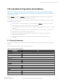
3 Pre-installation PreparationandGuidelines 15
3.1 Planning Dimensions 15
3.2 Considerations for Air Distribution 16
3.3 Connections and System Setup 16
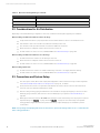
3.4 Operating Conditions 17
3.4.1 Cooling, Humidification, and Dehumidification 17
3.4.2 Heating 17
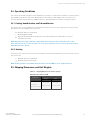
3.5 Shipping Dimensions andUnitWeights 17
4 Equipment Inspection and Handling 19
4.1 Packaging Material 20
4.2 Handling the Unit While Packaged 20
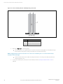
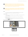
4.3 Unpacking the Unit 20
4.3.1 Removing the Unit from the Skid with a Forklift 22
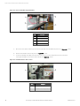
4.3.2 Removing the Unit from the Skid Using Rigging 23
4.3.3 Moving the Unit with Piano Jacks 26
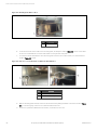
4.4 Placing the Unit on a Floor Stand 28
5 Piping and Refrigerant Requirements 29
5.1 Fluid Piping forAir Cooled, Water/Glycol Cooled,andChilled WaterPipingApplications 30
5.1.1 Field Installed, Gravity Fed Drain Line Requirements 30
5.1.2 Water Supply Line Requirements for the Optional Humidifier 32
5.2 Refrigerant Piping and Charging 33
5.2.1 Refrigerant Piping Guidelines forAir CooledSystems 34
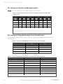
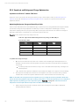
5.2.2 Refrigerant Line Sizes and Equivalent Lengths 36
5.2.3 Refrigerant Charge Requirements for Air Cooled Systems 36
5.2.4 Additional Oil Requirements forScrollandDigital ScrollCompressors 37
5.2.5 Evacuation, Leak Testing, and Charging Air CooledSystems withTXV andwithoutReceivers 39
5.2.6 Evacuation, Leak Testing, and Charging Air Cooled Systems withVertiv™ Liebert® Lee-Temp Flooded
Condenser Head PressureControlSystem 44
5.2.7 Evacuation, Leak Testing, andChargingAir Cooled Systems withEEVandUnheatedReceivers 47
5.2.8 Superheat and Refrigerant Charge Optimization 50
5.3 Water/Glycol and Chilled Water Loop Piping Guidelines 51
5.3.1 Leak Checking for Unit and Field Installed Piping 53
Proprietary and Confidential ©2023 Vertiv Group Corp. i
Vertiv™ Liebert® PDX and Liebert® PCW Installer/User Guide

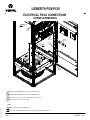
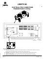
6 Electrical Connections 55
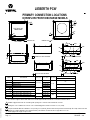
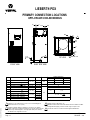
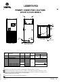
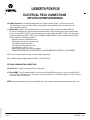
6.1 Wye and Delta Connected Power Supply for Vertiv™ Liebert® PDX and Vertiv™ Liebert® PCW 57
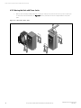
6.2 Supply Temperature Sensor 58
6.3 Return Air Sensor 58
6.3.1 Internal Temperature/Humidity Sensor 58
6.3.2 Remote Temperature/Humidity Sensor 58
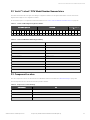
6.4 2T Wired Remote Sensors 59
7 Checklist for Completed Installation 61
7.1 Moving and Placing Equipment 61
7.2 Electrical Installation Checks 61
7.3 Piping Installation Checks 61
7.4 Other Installation Checks 62
8 Initial Start-up Checks andCommissioning ProcedureforWarrantyInspection 63
9 Maintenance 65
9.1 Filters 66
9.1.1 Filter Replacement for Downflow Units 67
9.1.2 Filter Replacement for Upflow Units 67
9.1.3 Filter Replacement for Upflow Units with Rear Return 67
9.2 Blower Drive System—EC Fans 68
9.2.1 Fan Impellers and Bearings Maintenance 69
9.2.2 Protective Features 69
9.2.3 Fan Assembly Troubleshooting 69
9.2.4 Replacing EC Fans in Downflow Models 73
9.2.5 Replacing EC Fans in Upflow Models 78
9.3 Infrared Humidifier Maintenance 81
9.3.1 Cleaning Humidifier Pan and Float Switch 82
9.3.2 Changing Humidifier Lamps 83
9.4 Steam Generating Humidifier Maintenance 85
9.4.1 Removing the Old Canister 87
9.4.2 Mandatory Cleaning of the Drain Valve 87
9.4.3 Installing the New Canister 88
9.4.4 Humidifier Troubleshooting 90
9.5 Condensate Drain and Condensate Pump System Maintenance 93
9.5.1 Condensate Drain 93
9.5.2 Condensate Pump 93
9.6 Air Cooled Condenser and Vertiv™ Liebert® Drycooler Maintenance 94
9.7 Electric Reheat Maintenance 94
9.8 Thermostatic Expansion Valve (TXV) Maintenance 94
9.8.1 Determining Suction Superheat 94
9.8.2 Adjusting Superheat Setting with the TXV 94
ii Proprietary and Confidential ©2023 Vertiv Group Corp.
Vertiv™ Liebert® PDX and Liebert® PCW Installer/User Guide

9.9 Electronic Expansion Valve (EEV) Maintenance 95
9.10 Compressor Maintenance 96
9.10.1 Compressor Oil 97
9.10.2 Scroll and Digital Scroll Compressor Maintenance 97
9.10.3 Replacement Compressors 97
9.10.4 Rotalock Valve on Scroll and Digital Scroll Compressors 98
9.10.5 Unloading Solenoid(s) on a Digital Scroll Compressor 98
9.10.6 Compressor Electrical Failure (Motor Burnout) 99
9.10.7 Replacing a Compressor with Electrical Failure (MotorBurnout) 99
9.10.8 Compressor Mechanical Failure 100
9.10.9 Replacing a Compressor with Mechanical Failure 100
9.11 Facility Fluid and Piping Maintenance forWaterandGlycolSystems 102
9.12 Glycol Solution Maintenance 103
9.13 Motorized Ball Valve (MBV) Maintenance (Digital Scroll Compressors) 104
9.13.1 MBV Control 104
9.13.2 MBV Control Method 104
9.13.3 MBV Adjustment 104
9.13.4 MBV Start Up 104
9.13.5 MBV Location 104
9.13.6 MBV Manual Control 104
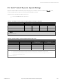
9.14 Vertiv™ Liebert® Drycooler Aquastat Settings 105
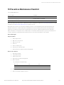
10 Preventive Maintenance Checklist 107
Appendices 113
Appendix A: Technical Support and Contacts 113
Appendix B: Vertiv™ Liebert® PDX Model Number Detail 115
Appendix C: Vertiv™ Liebert® PCW Model Number Detail 119
Appendix D: Submittal Drawings 123
Proprietary and Confidential ©2023 Vertiv Group Corp. iii
Vertiv™ Liebert® PDX and Liebert® PCW Installer/User Guide

iv Proprietary and Confidential ©2023 Vertiv Group Corp.
This page intentionally left blank
Vertiv™ Liebert® PDX and Liebert® PCW Installer/User Guide

1 Important Safety Instructions
SAVE THESE INSTRUCTIONS
This manual contains important safety instructions that should be followed during the installation and maintenance of the
Vertiv™ Liebert® PDX and Vertiv™ Liebert® PCW. Read this manual thoroughly before attempting to install or operate this unit.
Only qualified personnel should move, install or service this equipment.
Adhere to all warnings, cautions, notices and installation, operating, and safety instructions on the unit and in this manual.
Follow all installation, operation, and maintenance instructions and all applicable national and local building, electrical, and
plumbing codes.
WARNING! Arc flash and electric shock hazard. Can cause serious injury or death. Building and equipment
damage may also result. Disconnect all local and remote electric power supplies and wear appropriate, OSHA-
approved personal protective equipment (PPE) per NFPA 70E before working within the electric control
enclosure. Customer must provide earth ground to unit, per NEC, CEC, and local codes, as applicable.
Verify with a voltmeter that power is Off. The Vertiv™ Liebert® iCOM™ controller does not isolate power from
the unit, even in the “Unit Off” mode. Some internal components still require and receive power even during
the “Unit Off” mode of the Liebert® iCOM™ controller. The factory-supplied, optional disconnect switch is
inside the unit. The line side of this switch contains live high voltage. The only way to ensure that there is NO
voltage inside the unit is to install and open a remote disconnect switch. Refer to unit electrical schematic.
Before proceeding with installation, read all instructions, verify that all the parts are included and check the
nameplate to be sure the voltage matches available utility power. Follow all local codes.
WARNING! Risk of electric shock. Can cause serious injury or death. Building and equipment damage may also
result. Open all local and remote electric power supply disconnect switches and verify that power is off with a
voltmeter before working within any electric connection enclosures. The Liebert® iCOM™ controller does not
isolate power from the unit, even in the "Unit Off" mode. Some internal components require and receive power
even during the "unit off" mode of the Liebert® iCOM™ controller.
Installation, service, and maintenance work must be performed only by properly trained and qualified
personnel and in accordance with applicable regulations and manufacturers’ specifications. Opening or
removing the covers to any equipment may expose personnel to lethal voltages within the unit even when it
is apparently not operating and the input wiring is disconnected from the electrical source.
WARNING! Risk of short circuits and electric shock. Can cause serious injury or death. Building and
equipment damage can result from cut insulation or damaged wires. Can cause overheated wiring, smoke,
fire, activation of fire suppression systems and EMS personnel, and loss of power to fans. Verify that all
wiring connections are tight and that all wiring is contained within the junction box prior to closing and
securing the cover.
Insert CSA certified or UL listed bushings into holes and/or knockouts used to route wiring through metal
panels to protect the wire insulation from contact with sheet metal edges.
1 Important Safety Instructions Proprietary and Confidential ©2023 Vertiv Group Corp. 1
Vertiv™ Liebert® PDX and Liebert® PCW Installer/User Guide

WARNING! Risk of improper wire sizing/rating and loose electrical connections causing overheated wire and
electrical connection terminals resulting in smoke or fire. Can cause serious injury or death. Building and
equipment damage may also result. Use correctly sized copper wire only and verify that all electrical
connections are tight before turning power On. Check all electrical connections periodically and tighten as
necessary.
WARNING! Risk of contact with high speed rotating fan blades. Can cause serious injury or death. Open all
local and remote electric power supply disconnect switches, verify with a voltmeter that power is off, and
verify that all fan blades have stopped rotating before working in the unit cabinet or on the fan assembly. If
control voltage is applied, the fan motor can restart without warning after a power failure. Do not operate the
unit with any or all cabinet panels removed. Do not operate upflow units without installing a plenum, duct
work or guard over the blower opening(s) on the top surface of the unit cabinet. Ductwork must be
connected to the blower(s), or a plenum must be installed on the blower deck for protection from rotating
blower wheel(s) on upflow units.
WARNING! Risk of over pressurization of the refrigeration system. Can cause serious injury or death. Building
and equipment damage may also result. Can cause explosive discharge of high pressure refrigerant, loss of
refrigerant, or environmental pollution. This unit contains fluids and gases under high pressure. Use extreme
caution when charging the refrigerant system. Do not pressurize the system higher than the design pressure
marked on the unit's nameplate.
WARNING! Risk of explosive discharge of high pressure refrigerant. Can cause serious injury or death.
Building and equipment damage may also result. Neutral and service ports on the compressor service valves
do not have a valve core. Front-seat the service valves and relieve pressure from the compressor before
loosening a part or a component attached to the service valve. Follow local codes to properly reclaim
refrigerant.
WARNING! Risk of improper wiring, piping, moving, lifting and handling. Can cause serious injury or death.
Building and equipment damage may also result. Installation and service of this equipment should be done
only by qualified personnel who have been specially-trained in the installation of air-conditioning equipment
and who are wearing appropriate, OSHA-approved PPE.
WARNING! Risk of top heavy unit falling over when improperly lifted or moved. Can cause serious injury or
death. Building and equipment damage may also result. Read all of the following instructions and verify that
all lifting and moving equipment is rated for the weight of the unit before attempting to move, lift, remove
packaging from or prepare the unit for installation. Unit weights are specified in Table 3.3 on page18 .
2 Proprietary and Confidential ©2023 Vertiv Group Corp. 1 Important Safety Instructions
Vertiv™ Liebert® PDX and Liebert® PCW Installer/User Guide

WARNING! Risk of extremely heavy fan modules dropping downward suddenly. Can cause serious injury or
death. Building and equipment damage may also result. Fan modules weigh in excess of 125 lb (56.7 kg) each.
Support fan modules before removing mounting hardware. Use caution to keep all body parts out of the fan
module pathway of movement during removal or repositioning. Only properly trained and qualified personnel
should work on this equipment.
More than one person may be required to complete the assembly and installation. Installer(s) must be
properly trained and qualified to lift, move, and manipulate very heavy equipment from floor level to the top
of the unit. Wear appropriate, OSHA-approved PPE when moving, lifting, installing, and removing the fan(s)
and plenum. Read and follow the lifting equipment and/or ladder manufacturer's operating instructions and
safety requirements.
WARNING! Risk of improper humidifier canister maintenance. Can cause serious injury or death. Building and
equipment damage may also result. Can cause fire suppression and alarm system activation, resulting in
building evacuation and mobilization of emergency fire and rescue services. Using a humidifier canister that
has reached the end of its service life can be extremely hazardous. If the canister cannot be replaced
immediately at the end of life condition, turn off the power and water supply to the humidifier and remove the
canister until a replacement canister can be installed. Do not ignore humidifier problem alarms. Resetting the
humidifier without addressing cause may result in fire or damage from leaking water. See Table 9.5 on
page91 for alarm corrective actions.
CAUTION: Risk of excessive refrigerant line pressure. Can cause equipment damage or injury resulting from
tubing and component rupture. Do not close off the refrigerant-line isolation valve for repairs unless a
pressure-relief valve is field installed in the line between the isolation valve and the check valve. The
pressure-relief valve must be rated 5% to 10% higher than the system-design pressure. An increase in
ambient temperature can cause the pressure of the isolated refrigerant to rise and exceed the system design
pressure rating (marked on the unit nameplate).
CAUTION: Risk of contact with sharp edges, splinters, and exposed fasteners. Can cause injury. Only properly
trained and qualified personnel wearing appropriate, OSHA-approved PPE should attempt to move, lift,
remove packaging from or prepare the unit for installation.
CAUTION: Risk of improper handling, heavy and lengthy parts. Can cause injury. Building and Equipment
damage may also result. Cabinet panels can exceed 5 feet (1.5 m) in length and weigh more than 35 lb. (15.9
kg). Follow relevant OSHA lifting recommendations and consider using a two-person lift for safe and
comfortable removal and installation of cabinet panels. Only properly trained and qualified personnel wearing
appropriate, OSHA-approved PPE should attempt to remove or install cabinet panels.
1 Important Safety Instructions Proprietary and Confidential ©2023 Vertiv Group Corp. 3
Vertiv™ Liebert® PDX and Liebert® PCW Installer/User Guide

CAUTION: Risk of improper moving, lifting and handling. Can cause injury. Building and equipment damage
may also result. Only properly trained and qualified personnel should work on this equipment. Evaporator fan
modules weigh in excess of 125 lb (56.7 kg). Use proper lifting techniques and wear appropriate OSHA-
approved PPE to avoid injury and dropping the fan module during removal. Equipment used in
handling/lifting, and/or installing the fan assembly must meet OSHA requirements. Use handling/lifting
equipment rated for the weight of the fan assembly. Use ladders rated for the weight of the fan assembly and
technicians if used during installation. Refer to handling/lifting, and/or installation equipment operating
manual for manufacturer's safety requirements and operating procedures.
CAUTION: Risk of heavy unit falling into defective raised floor. Can cause injury and equipment damage. Prior
to installation, all floor tiles immediately around floor stand are to be removed and inspected. Make sure tiles
are not cracked, and ribs have not been cut. If free from defects, re-install. Replace with new tiles if defects
are found.
CAUTION: Risk of contact with hot surfaces. Can cause injury. Personal burn injury can be the result of
touching an electronics housing, fan motor, and some electrical components that are extremely hot during
unit operation. Allow sufficient time for them to cool to a touch safe temperature before working within the
unit cabinet. Use extreme caution and wear appropriate, OSHA-approved PPE when working on or near hot
components, including when replacing or performing maintenance on the fans.
CAUTION: Risk of humidifier canister meltdown, smoke, and fire. Can cause fire suppression system
activation, fire and smoke alarm activation, building evacuation, dispatching of fire and rescue equipment and
personnel, and water leaks resulting in expensive equipment or building damage, injury or death. Check
steam generating humidifier electrode plugs to ensure that they are pressed firmly onto pins. Loose
connections will cause overheating of cylinder and plugs.
CAUTION: Risk of contact with hot surfaces. Can cause burn injury. The humidifier canister and steam
discharge lines are extremely hot during operation. Allow sufficient time for them to cool to a touch-safe
temperature before handling. Use extreme caution and wear appropriate, OSHA-approved PPE when
performing maintenance on the humidifier.
CAUTION: Risk of contact with hot surfaces. Can cause injury. Personal burn injury can be the result of
touching a humidifier reservoir pan and/or water contained within the pan, and some electrical components
that are extremely hot during unit operation. Allow sufficient time for them to cool to a touch-safe
temperature before working within the unit cabinet.
Use extreme caution and wear appropriate, OSHA-approved PPE when working on or near hot components,
including when replacing or performing maintenance on the infrared humidifier parts inclusive of its bulbs,
metal enclosure, humidifier reservoir pan and/or water contained within the pan, and drain tubing. All infrared
humidifier parts are very hot during and remain very hot shortly after operation.
4 Proprietary and Confidential ©2023 Vertiv Group Corp. 1 Important Safety Instructions
Vertiv™ Liebert® PDX and Liebert® PCW Installer/User Guide

CAUTION: Risk of improper handling of boiling water. Can cause leaks, equipment and building damage, or
burn injury. The unit requires a drain line that may contain boiling water. Only properly trained and qualified
personnel wearing appropriate, OSHA-approved PPE should service the drain line or work on parts near or
connected to the drain line.
CAUTION: Risk of improper piping installation, leak checking, fluid chemistry and fluid maintenance. Can
cause injury. Building and equipment damage may also result. Installation and service of this equipment
should be done only by qualified personnel who have been specially-trained in the installation of air-
conditioning equipment and who are wearing appropriate, OSHA-approved PPE.
CAUTION: Risk of smoke generation. Can cause injury. Can cause fire suppression and alarm system
activation, resulting in building evacuation and mobilization of emergency fire and rescue services. Start-up
operation of optional electric reheat elements can create smoke or fumes that can activate the facility alarm
and fire suppression system. Prepare and take appropriate steps to manage this possibility. Activating reheat
during initial start-up may burn off particulates from electric reheat elements. Before beginning initial start-
up checks, make certain that unit was installed according to the instructions in this manual. All exterior
panels must be in place.
CAUTION: Risk of exposure to harmful noise levels. Can cause hearing injury or loss. Depending on the
installation and operating conditions, a sound pressure level greater than 70dB(A) may arise. Take
appropriate technical safety measures. Operating personnel must wear appropriate, OSHA-approved PPE and
observe all appropriate hearing protection safety requirements.
NOTICE
Risk of improper power supply connection. Can cause equipment damage and loss of warranty coverage.
Prior to connecting any equipment to a main or alternate power source (for example: backup generator systems)
for start-up, commissioning, testing or normal operation, ensure that these sources are correctly adjusted to the
nameplate voltage and frequency of all equipment to be connected. In general, power source voltages should be
stabilized and regulated to within ±10% of the load nameplate nominal voltage. Also, ensure that no three phase
sources are single phased at any time.
NOTICE
Risk of oil contamination with water. Can cause equipment damage.
Vertiv™ Liebert® PDX systems require the use of POE (polyolester) oil. POE oil absorbs water at a much faster
rate when exposed to air than previously used oils. Because water is the enemy of a reliable refrigeration system,
extreme care must be used when opening systems during installation or service. If water is absorbed into the
POE oil, it will not be easily removed and will not be removed through the normal evacuation process. If the oil is
too wet, it may require an oil change. POE oils also have a property that makes them act as a solvent in a
refrigeration system. Maintaining system cleanliness is extremely important because the oil will tend to bring any
foreign matter back to the compressor.
1 Important Safety Instructions Proprietary and Confidential ©2023 Vertiv Group Corp. 5
Vertiv™ Liebert® PDX and Liebert® PCW Installer/User Guide

NOTICE
Risk of improper refrigerant charging. Can cause equipment damage.
Refrigerant charge must be weighed into air cooled compressorized systems before they are started. Starting
scroll and digital scroll compressors without proper refrigerant charging can cause the compressors to operate
at less than 5°F (–15°C) evaporator temperature and at less than 20psig (138kPa). Operation for extended
periods at less than 20psig (138kPa) can cause premature compressor failure.
NOTICE
Risk of piping system corrosion and freezing fluids. Can cause leaks resulting in equipment and expensive
building damage. Cooling coils, heat exchangers, and piping systems are at high risk of freezing and premature
corrosion. Fluids in these systems must contain an inhibitor to prevent premature corrosion.
The system coolant fluid must be analyzed by a competent fluid treatment specialist before start-up to establish
the inhibitor level and evaluated at regularly scheduled intervals throughout the life of the system to determine
the pattern of inhibitor depletion. The fluid complexity and variations of required treatment programs make it
extremely important to obtain the advice of a competent and experienced fluid treatment specialist and follow a
regularly scheduled coolant fluid system maintenance program.
Fluid chemistry varies greatly as do the required additives, called inhibitors, that reduce the corrosive effect of
the fluids on the piping systems and components.
The chemistry of the coolant fluid used must be considered, because some sources may contain corrosive
elements that reduce the effectiveness of the inhibited formulation. Sediment deposits prevent the formation of
a protective oxide layer on the inside of the coolant system components and piping. The coolant fluid must be
treated and circulating through the system continuously to prevent the buildup of deposits and/or growth of
bacteria. Proper inhibitor maintenance must be performed to prevent corrosion of the system.
Consult fluid manufacturer for testing and maintenance of inhibitors.
Commercial grade coolant fluid is generally less corrosive to the common metals of construction than water
itself. It will, however, assume the corrosivity of the coolant fluid from which it is prepared and may become
increasingly corrosive with use if not properly inhibited.
Vertiv recommends installing a monitored fluid detection system that is wired to activate the automatic closure
of field installed coolant fluid supply and return shutoff valves to reduce the amount of coolant fluid leakage and
consequential equipment and building damage. The shutoff valves must be sized to close off against the
maximum coolant fluid system pressure in case of a catastrophic fluid leak.
6 Proprietary and Confidential ©2023 Vertiv Group Corp. 1 Important Safety Instructions
Vertiv™ Liebert® PDX and Liebert® PCW Installer/User Guide

NOTICE
Risk of no flow condition. Can cause equipment damage. Do not leave the water/coolant fluid supply circuit in a
no flow condition. Idle fluid allows the collection of sediment that prevents the formation of a protective oxide
layer on the inside of tubes. Keep unit switched on and water/coolant fluid supply circuit system operating
continuously.
NOTICE
Risk of clogged or leaking drain lines and leaking water supply lines. Can cause equipment and building damage.
This unit requires a water drain connection. Drain lines must be inspected at start-up and periodically, and
maintenance must be performed to ensure that drain water runs freely through the drain system and that lines
are clear and free of obstructions and in good condition with no visible sign of damage or leaks. This unit may
also require an external water supply to operate.
Improper installation, application, and service practices can result in water leakage from the unit. Water leakage
can result in catastrophic and expensive building and equipment damage and loss of critical data center
equipment.
Do not locate unit directly above any equipment that could sustain water damage.
We recommend installing a monitored fluid detection system to immediately discover and report coolant fluid
system and condensate drain line leaks.
NOTICE
Risk of leaking chilled water lines. Can cause equipment and building damage.
Lines and joints must be inspected regularly. Improper installation, application and service practices can result in
water leakage from the unit. Water leakage can result in severe property damage and loss of critical data center
equipment. Do not locate unit directly above any equipment that could sustain water damage.
Vertiv recommends installing monitored leak detection equipment for the unit and supply and return lines.
NOTICE
Risk of a catastrophic water circuit rupture. Can cause expensive building and equipment damage.
Install an overflow drain pan under the unit with a monitored leak detection system in the pan and shutoff valves
in the supply and return water lines that automatically close if water is detected by the leak detection system.
The shutoff valves should be spring return and must be rated for a close off pressure that is the same as or
higher than the supply water pressure. If it is not possible to install an overflow drain pan, then a monitored leak
detection system should be installed in the base of the unit or under the unit to actuate the shutoff valves
immediately on a leak detection signal.
The overflow drain pan should have a drain line connected to it that flows to a floor drain or maintenance sink in
case of a shutoff valve or leak detection system malfunction.
NOTICE
Risk of improper water supply. Can reduce humidifier efficiency or obstruct humidifier plumbing.
Do not use a hot water source. It will cause deposits that will eventually block the fill valve opening.
1 Important Safety Instructions Proprietary and Confidential ©2023 Vertiv Group Corp. 7
Vertiv™ Liebert® PDX and Liebert® PCW Installer/User Guide

NOTICE
Risk of water backing up in the drain line. Leaking and overflowing water can cause equipment and building
damage.
Do not install an external trap in the drain line. This line already has a factory installed trap inside the cabinet.
Installation of a second trap will prevent drain water flow and will cause the water to overflow the drain pan.
Sagging condensate drain lines may inadvertently create an external trap.
NOTICE
Risk of passageway interference. Can cause unit and/or structure damage. The unit may be too large to fit
through a passageway while on oroff the skid. Measure the unit and passageway dimensions, and refer to the
installation plans prior to moving the unit to verify clearances.
NOTICE
Risk of damage from forklift. Can cause unit damage. Keep tines of the forklift level and at a height suitable to fit
below the skid and/or unit to prevent exterior and/or underside damage.
NOTICE
Risk of improper storage. Can cause unit damage.
Keep the unit upright, indoors and protected from dampness, freezing temperatures, and contact damage.
NOTICE
Risk of equipment snagging cables and wiring. Can damage the unit wiring and components.
Carefully monitor the position of the EC-fan wire harnesses and other parts while lowering the fan to be sure that
they are not caught or pinched.
NOTICE
Risk of improper control circuits. Can cause equipment damage.
When using jumpers for troubleshooting, always remove jumpers when maintenance is complete. Jumpers left
connected could override controls and cause equipment damage.
NOTICE
Risk of improper filter installation. Can cause filter collapse and airflow reduction.
NOTICE
Condenser fans should be operated manually if they have not run for an extended time in an outdoor
environment. Before enabling the condenser for normal cooling operation fans should be run at full speed for at
least three hours once a month to move the bearings and allow any condensate that may have ingressed to
evaporate. Condenser firmware release 1.06.045 & later include settings to operate condenser fans if they have
been inactive for more than 30 days.
8 Proprietary and Confidential ©2023 Vertiv Group Corp. 1 Important Safety Instructions
Vertiv™ Liebert® PDX and Liebert® PCW Installer/User Guide

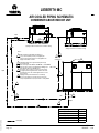
NOTE: The Liebert® indoor cooling unit has a factory installed high pressure safety switch in the high side refrigerant
circuit. Consult local building codes to determine whether the Vertiv™Liebert® MC units without receivers will require
field provided pressure-relief devices such as a fusible plug. A pressure relief valve is provided with Vertiv™ Liebert®
Lee-Temp receivers and an integral, fusible plug is provided on PDX-EEV unheated receivers.
Agency Listed
Standard 60Hz units are CSA Certified to the harmonized U.S. and Canadian product safety standard CSA C22.2 No 236/UL
1995 for “Heating and Cooling Equipment” and are marked with the CSA c-us logo.
1 Important Safety Instructions Proprietary and Confidential ©2023 Vertiv Group Corp. 9
Vertiv™ Liebert® PDX and Liebert® PCW Installer/User Guide

10 Proprietary and Confidential ©2023 Vertiv Group Corp. 1 Important Safety Instructions
This page intentionally left blank
Vertiv™ Liebert® PDX and Liebert® PCW Installer/User Guide

2 Nomenclature and Components
This section describes the model number for Vertiv™ Liebert® PDX and Vertiv™ Liebert® PCW units and components.
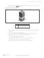
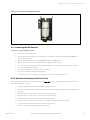
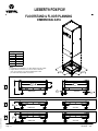
Figure 2.1 Liebert® PDX and Liebert® PCW Views
Item Description
1 Top discharge, front return unit
2 Raised floor discharge unit
3 Three-way floor level discharge unit
2 Nomenclature and Components Proprietary and Confidential ©2023 Vertiv Group Corp. 11
Vertiv™ Liebert® PDX and Liebert® PCW Installer/User Guide

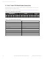
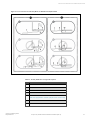
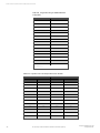
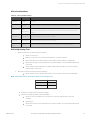
2.1 Vertiv™ Liebert® PDX ModelNumber Nomenclature
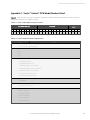
The tables below describe each digit of the 25 digitconfigurationnumber. The 14 digit model number consists of the first 10
digits and last 4 digits of the configuration number.
For the full description of configuration and model number refer to Vertiv™ Liebert® PDX Model Number Detail on page115 .
Model Number Digits 1 to 10 Model Details ModelNumber Digits
11to14
1 2 3 4 5 6 7 8 9 10 11 12 13 14 15 16 17 18 19 20 21 22 23 24 25
P X 0 2 9 D A 1 A D H 2 2 8 0 1 P L B F P A # # #
Table 2.1 Liebert® PDX 25 Digit Configuration Number
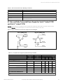
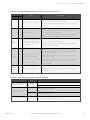
Digits 1 and 2 = Unit Family Digit 15 = Coil, Valve Type, and Pressure Rating
Digit 3, 4, 5 = Nominal Cooling Capacity, kW Digit 16 = Enclosure Options
Digit 6 = Air Direction and Discharge Digit 17 = High Voltage Options
Digit 7 = System Type Digit 18 = Low Voltage Option Packages
Digit 8 = Fan Type Digit 19 = Monitoring
Digit 9 = Power Supply Digit 20 = Sensors
Digit 10 = Compressor and Valve (R-410A) Digit 21 = Packaging
Digit 11 = Humidifier Digit 22 = Factory Configuration Code
Digit 12 = Display Digit 23-25 = Factory Configuration Number
Digit 13 = Reheat N/A
Digit 14 = Air Filter N/A
Table 2.2 Liebert® PDX Model Number Digit Summary
12 Proprietary and Confidential ©2023 Vertiv Group Corp. 2 Nomenclature and Components
Vertiv™ Liebert® PDX and Liebert® PCW Installer/User Guide

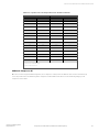
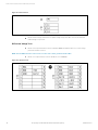
2.2 Vertiv™ Liebert® PCW Model Number Nomenclature
The tables below describe each digit of the 25 digitconfigurationnumber. The 14 digit model number consists of the first 10
digits and last 4 digits of the configuration number.
For the full description of configuration and model number refer to Vertiv™ Liebert® PCW Model Number Detail on page119 .
Model Number Digits 1 to 10 Model Details ModelNumberDigits 11 to
14
1 2 3 4 5 6 7 8 9 10 11 12 13 14 15 16 17 18 19 20 21 22 23 24 25
P W 0 2 9 D C 1 A D H 2 2 8 H 1 P L B F P A # # #
Table 2.3 Liebert® PCW 25 Digit Configuration Number
Digits 1 and 2 = Unit Family Digit 15 = Coil
Digit 3, 4, 5 = Nominal Cooling Capacity, kW Digit 16 = Enclosure Options
Digit 6 = Air Discharge Digit 17 = High Voltage Options
Digit 7 = System Type Digit 18 = Low Voltage Option Packages
Digit 8 = Fan Type Digit 19 = Monitoring
Digit 9 = Power Supply Digit 20 = Sensors
Digit 10 = Chilled Water Valve and Pressure Digit 21 = Packaging
Digit 11 = Humidifier Digit 22 = Factory Configuration Code
Digit 12 = Display Digit 23-25 = Factory Configuration Number
Digit 13 = Reheat N/A
Digit 14 = Air Filter N/A
Table 2.4 Liebert® PCW Model Number Digit Summary
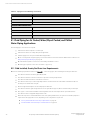
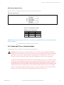
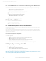
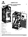
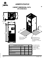
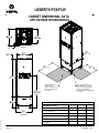
2.3 Component Location
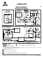
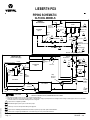
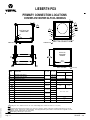
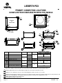
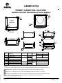
The unit component locations are described in the submittal documents included in the Submittal Drawings on page123 .
The following table lists the relevant documents by number and title.
Document Number Title
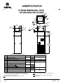
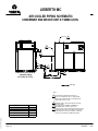
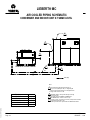
DPN003004 Liebert® PDX Component Location Diagram, Downflow Models
DPN003005 Liebert® PDX Component Location Diagram, Upflow Models
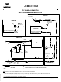
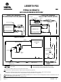
DPN003020 Liebert® PCW Component Location Diagram, Downflow Models
DPN003021 Liebert® PCW Component Location Diagram, Upflow Models
Table 2.5 Component Location Drawings
2 Nomenclature and Components Proprietary and Confidential ©2023 Vertiv Group Corp. 13
Vertiv™ Liebert® PDX and Liebert® PCW Installer/User Guide

14 Proprietary and Confidential ©2023 Vertiv Group Corp. 2 Nomenclature and Components
This page intentionally left blank
Vertiv™ Liebert® PDX and Liebert® PCW Installer/User Guide
Page is loading ...
Page is loading ...
Page is loading ...
Page is loading ...
Page is loading ...
Page is loading ...
Page is loading ...
Page is loading ...
Page is loading ...
Page is loading ...
Page is loading ...
Page is loading ...
Page is loading ...
Page is loading ...
Page is loading ...
Page is loading ...
Page is loading ...
Page is loading ...
Page is loading ...
Page is loading ...
Page is loading ...
Page is loading ...
Page is loading ...
Page is loading ...
Page is loading ...
Page is loading ...
Page is loading ...
Page is loading ...
Page is loading ...
Page is loading ...
Page is loading ...
Page is loading ...
Page is loading ...
Page is loading ...
Page is loading ...
Page is loading ...
Page is loading ...
Page is loading ...
Page is loading ...
Page is loading ...
Page is loading ...
Page is loading ...
Page is loading ...
Page is loading ...
Page is loading ...
Page is loading ...
Page is loading ...
Page is loading ...
Page is loading ...
Page is loading ...
Page is loading ...
Page is loading ...
Page is loading ...
Page is loading ...
Page is loading ...
Page is loading ...
Page is loading ...
Page is loading ...
Page is loading ...
Page is loading ...
Page is loading ...
Page is loading ...
Page is loading ...
Page is loading ...
Page is loading ...
Page is loading ...
Page is loading ...
Page is loading ...
Page is loading ...
Page is loading ...
Page is loading ...
Page is loading ...
Page is loading ...
Page is loading ...
Page is loading ...
Page is loading ...
Page is loading ...
Page is loading ...
Page is loading ...
Page is loading ...
Page is loading ...
Page is loading ...
Page is loading ...
Page is loading ...
Page is loading ...
Page is loading ...
Page is loading ...
Page is loading ...
Page is loading ...
Page is loading ...
Page is loading ...
Page is loading ...
Page is loading ...
Page is loading ...
Page is loading ...
Page is loading ...
Page is loading ...
Page is loading ...
Page is loading ...
Page is loading ...
Page is loading ...
Page is loading ...
Page is loading ...
Page is loading ...
Page is loading ...
Page is loading ...
Page is loading ...
Page is loading ...
Page is loading ...
Page is loading ...
Page is loading ...
Page is loading ...
Page is loading ...
Page is loading ...
Page is loading ...
Page is loading ...
Page is loading ...
Page is loading ...
Page is loading ...
Page is loading ...
Page is loading ...
Page is loading ...
Page is loading ...
Page is loading ...
Page is loading ...
Page is loading ...
Page is loading ...
Page is loading ...
Page is loading ...
Page is loading ...
Page is loading ...
Page is loading ...
Page is loading ...
Page is loading ...
Page is loading ...
Page is loading ...
Page is loading ...
Page is loading ...
Page is loading ...
Page is loading ...
Page is loading ...
Page is loading ...
Page is loading ...
Page is loading ...
Page is loading ...
Page is loading ...
Page is loading ...
Page is loading ...
Page is loading ...
Page is loading ...
Page is loading ...
Page is loading ...
Page is loading ...
Page is loading ...
Page is loading ...
Page is loading ...
Page is loading ...
Page is loading ...
Page is loading ...
Page is loading ...
Page is loading ...
Page is loading ...
Page is loading ...
Page is loading ...
Page is loading ...
Page is loading ...
Page is loading ...
Page is loading ...
-
 1
1
-
 2
2
-
 3
3
-
 4
4
-
 5
5
-
 6
6
-
 7
7
-
 8
8
-
 9
9
-
 10
10
-
 11
11
-
 12
12
-
 13
13
-
 14
14
-
 15
15
-
 16
16
-
 17
17
-
 18
18
-
 19
19
-
 20
20
-
 21
21
-
 22
22
-
 23
23
-
 24
24
-
 25
25
-
 26
26
-
 27
27
-
 28
28
-
 29
29
-
 30
30
-
 31
31
-
 32
32
-
 33
33
-
 34
34
-
 35
35
-
 36
36
-
 37
37
-
 38
38
-
 39
39
-
 40
40
-
 41
41
-
 42
42
-
 43
43
-
 44
44
-
 45
45
-
 46
46
-
 47
47
-
 48
48
-
 49
49
-
 50
50
-
 51
51
-
 52
52
-
 53
53
-
 54
54
-
 55
55
-
 56
56
-
 57
57
-
 58
58
-
 59
59
-
 60
60
-
 61
61
-
 62
62
-
 63
63
-
 64
64
-
 65
65
-
 66
66
-
 67
67
-
 68
68
-
 69
69
-
 70
70
-
 71
71
-
 72
72
-
 73
73
-
 74
74
-
 75
75
-
 76
76
-
 77
77
-
 78
78
-
 79
79
-
 80
80
-
 81
81
-
 82
82
-
 83
83
-
 84
84
-
 85
85
-
 86
86
-
 87
87
-
 88
88
-
 89
89
-
 90
90
-
 91
91
-
 92
92
-
 93
93
-
 94
94
-
 95
95
-
 96
96
-
 97
97
-
 98
98
-
 99
99
-
 100
100
-
 101
101
-
 102
102
-
 103
103
-
 104
104
-
 105
105
-
 106
106
-
 107
107
-
 108
108
-
 109
109
-
 110
110
-
 111
111
-
 112
112
-
 113
113
-
 114
114
-
 115
115
-
 116
116
-
 117
117
-
 118
118
-
 119
119
-
 120
120
-
 121
121
-
 122
122
-
 123
123
-
 124
124
-
 125
125
-
 126
126
-
 127
127
-
 128
128
-
 129
129
-
 130
130
-
 131
131
-
 132
132
-
 133
133
-
 134
134
-
 135
135
-
 136
136
-
 137
137
-
 138
138
-
 139
139
-
 140
140
-
 141
141
-
 142
142
-
 143
143
-
 144
144
-
 145
145
-
 146
146
-
 147
147
-
 148
148
-
 149
149
-
 150
150
-
 151
151
-
 152
152
-
 153
153
-
 154
154
-
 155
155
-
 156
156
-
 157
157
-
 158
158
-
 159
159
-
 160
160
-
 161
161
-
 162
162
-
 163
163
-
 164
164
-
 165
165
-
 166
166
-
 167
167
-
 168
168
-
 169
169
-
 170
170
-
 171
171
-
 172
172
-
 173
173
-
 174
174
-
 175
175
-
 176
176
-
 177
177
-
 178
178
-
 179
179
-
 180
180
-
 181
181
-
 182
182
-
 183
183
-
 184
184
-
 185
185
-
 186
186
-
 187
187
-
 188
188


Vertiv Liebert® PDX and Liebert® PCW User manual
- Category
- Split-system air conditioners
- Type
- User manual
Ask a question and I''ll find the answer in the document
Finding information in a document is now easier with AI