Page is loading ...

&#&!& %765
1
2
3
4
6
5
NM
FFCFA
G4000 / G4001 / G4000N / G6000 / G6001 / G6000N / G5000 / G6500
G2500 / G2500N
7
8
7
8
9
10
&#&!& %765
NM
FFCFA
G4000 / G4001 / G4000N / G6000 / G6001 / G6000N / G5000 / G6500
G2500 / G2500N
11
12
11
12
13
14
SX DX
SX DX
G4000 / G4001 / G4000N / G2500 / G2500N
SX DX
G6000 / G6000N / G5000 / G6500
GARD SX-DX
www.came.com
Italiano
IT
IT
English
EN
EN
Français
FR
FR
Русский
RU
RU
FA00700M4A - ver. 1 - 02/2017
FA00700M4A

FA00700M4A - ver. 1 - 02/2017
TRANSFORMATION BARRIÈRES GARD
Ce document contient les instructions permettant de transformer
une barrière GARD de gauche à droite et vice versa. Conserver
le manuel d'installation de la barrière à portée de main.
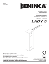
- Par barrière à gauche (G), l'on entend une barrière avec armoire
montée à G, lisse fermant à D et porte visible :
1. Côté entrée
2. Zone interne
3. Armoire
- Par barrière à droite (D), l'on entend une barrière avec armoire
montée à D, lisse fermant à G et porte visible :
4. Côté entrée
5. Zone interne
6. Porte
N.B. : il convient, si possible, de positionner l'armoire de manière
à ce que la porte soit dirigée vers l'intérieur afi n de faciliter les
opérations de montage et/ou d'entretien et d'optimiser la sécurité.
La zone interne est celle qui permet de contrôler les accès et les
sorties e ectués avec la barrière Gard.
PROCÉDURE PAS À PAS POUR LA TRANSFORMATION DE
BARRIÈRES G2500 / G2500N - G4000 / G4000N / G4001
- En cas de barrière déjà montée, tourner la lisse en position
verticale et l'enlever;
- débloquer le motoréducteur à l'aide de la clé prévue à cet e et ;
- extraire le ressort de compensation, après l'avoir correctement
débandé, en intervenant sur l'écrou , le ressort (par
dévissage) et le boulon de fi xation de l'articulation ;
- enlever le groupe fi n de course ;
- détacher le groupe de la buté mécanique supérieure (butée
à support) ;
- déplacer la butée mécanique inférieure de l'autre côté ;
- tourner à 270° le bras du motoréducteur :
• dans le sens contraire à celui des aiguilles d'une montre
pour une transformation de D à G
• dans le sens des aiguilles d'une montre pour une
transformation de G à D ;
- remettre le groupe de la buté mécanique supérieure (couple
de serrage: 77,5 Nm) et déplacer la butée de l'autre côté;
- tourner la plaque de fi xation de la lisse à 180° (couple de
serrage des vis: 45 Nm) ;
- remettre le groupe fi n de course de l'autre côté;
- inverser les câbles de connexion des minirupteurs de fi n de
course aux polarités du moteur sur le tableau électrique ;
- bloquer le motoréducteur;
- raccrocher le ressort et positionner le groupe. Si la barrière était
déjà installée, répéter les opérations d'ajustage de la linéarité
horizontale/verticale et d'équilibrage de la lisse.
PROCÉDURE PAS À PAS POUR LA TRANSFORMATION DE
BARRIÈRES G5000 / G6000 / G6000N / G6001
- En cas de barrière déjà montée, tourner la lisse en position
verticale et l'enlever;
- débloquer le motoréducteur à l'aide de la clé prévue à cet e et ;
- extraire le ressort (ou les ressorts) de compensation, après
l'avoir correctement débandé, en intervenant sur l'écrou
, le ressort (par dévissage) et le boulon de fi xation de
l'articulation ;
- détacher le levier de transmission du bras-levier en enlevant
la vis spécifi que ;
- dégager le bras-levier de l'arbre de la lisse en enlevant
les 2 goupilles élastiques .
Tourner à 180° l'arbre de la lisse en intervenant sur les plaques
de fi xation de la lisse .
Tourner le bras-levier à 90° vers le bas et le bloquer à nouveau
sur l'arbre de la lisse à l'aide des goupilles élastiques.
- dévisser et déplacer la butée mécanique supérieure de l'autre côté;
- détacher et tourner à 180° la butée mécanique inférieure
(couple de serrage: 77,5 Nm) en éloignant légèrement le bras
du motoréducteur;
- raccrocher le levier de transmission du bras-levier (couple de
serrage: 77,5 Nm);
- enlever le couvercle du groupe fi n de course ; détacher et
tourner à 90° le bloc d'activation des minirupteurs , comme
indiqué sur la fi gure, et refermer le couvercle;
- inverser les câbles de connexion des minirupteurs de fi n de
course et les polarités du moteur sur le tableau électrique ;
- bloquer le motoréducteur;
- raccrocher le ressort (ou les ressorts) et positionner le groupe. Si
la barrière était déjà installée, répéter les opérations d'ajustage
de la linéarité horizontale/verticale et d'équilibrage de la lisse.
BRANCHEMENTS ÉLECTRIQUES À MODIFIER SUR LES
TABLEAUX DE COMMANDE DES BARRIÈRES - CONNEXIONS
BARRIÈRE G
7. Minirupteur d'ouverture (câble de connexion à la borne FA «
BLANC »)
8. Minirupteur de fermeture (câble de connexion à la borne FC
« ROUGE »)
9. Moteur 24 V (câble de connexion à la borne M « MARRON
»; câble de connexion à la borne N « BLEU »)
10. Moteur 230 V (câble de connexion à la borne V « MARRON
»; câble de connexion à la borne U « BLEU »)
BRANCHEMENTS ÉLECTRIQUES À MODIFIER SUR LES
TABLEAUX DE COMMANDE DES BARRIÈRES - CONNEXIONS
BARRIÈRE D
11. Minirupteur d'ouverture (câble de connexion à la borne
FC « BLANC »)
12. Minirupteur de fermeture (câble de connexion à la borne
FA « ROUGE »)
13. Moteur 24 V (câble de connexion à la borne M « BLEU »;
câble de connexion à la borne N « MARRON »)
14. Moteur 230 V (câble de connexion à la borne V « BLEU »;
câble de connexion à la borne U « MARRON »)
FR
GARD BARRIER CONVERSION
This document features instructions for converting a GARD barrier
from left-hand to right-hand and vice-versa. You will also need
the barrier's installation manual.
- Left-hand barrier (LH), means a barrier with the cabinet mounted
on the left, the barrier-arm closes on the right and the inspection
fl ap is visible :
1. Entrance side
2. Internal zone
3. Cabinet
- Right-hand barrier (RH), means a barrier with the cabinet
mounted on the right, the barrier-arm closes on the left and
the inspection fl ap is visible :
4. Entrance side
5. Internal zone
6. Inspection fl ap
N.B.: Unless specifi cally required, we suggest mounting the
cabinet with the inspection fl ap directed inwards, for easier
mounting and /or maintenance, as well as for security reasons.
Internal zone, means the area of which you wish to control the
access and exit using the GARD barrier.
STEP-BY-STEP PROCEDURE FOR CONVERTING THE G2500 /
G2500N - G4000 / G4000N /G4001 BARRIERS
- If already mounted, turn the barrier-arm to the vertical position
and then remove it;
- using the apposite key release the gearmotor;
- extract the counter-weight spring, after loosening it, by turning
the spring-nut , and joint fastening bolt ;
- remove the limit-switch assembly ;
- detach the upper mechanical-stop assembly (stop and
support) ;
- move the lower mechanical-stop to the opposite side;
- turn the gearmotor arm 270° :
• counter-clockwise to convert it from right-hand to left-
hand, whereas, turn it clockwise to convert it from left-hand
to right-hand;
- refi t the upper mechanical-stop assembly (tightening torque:
77.5 Nm) and move the stop to the opposite side ;
- turn the barrier-arm anchoring plate by 180° ( screw
tightening-torque: 45 Nm);
- refi t the limit switch assembly to the opposite side;
- invert the limit-switch micro-switches connection cables and
the motor polarities on the electrical panel ;
- lock the gearmotor;
- hook the spring back up and proceed with fi tting the assembly.
With already installed barriers, you will need to reset the
horizontal/vertical alignment and barrier-arm balancing.
STEP-BY-STEP PROCEDURE FOR CONVERTING THE G5000 /
G6000 / G6000N / G6001 BARRIERS
- If already mounted, turn the barrier-arm to the vertical position
and then remove it;
- using the apposite key release the gearmotor;
- extract the counter-weight spring, after loosening it, by turning
the spring-nut , and joint fastening bolt ;
- unhook the transmission lever from the lever arm by
removing the relative screw ;
-free the lever arm from the barrier-shaft , by removing
th elastic plugs .
Turn the barrier-shaft 180°, by acting on the barrier-arm
anchoring plates .
Turn the lever arm 90° downwards, then re-block it onto the barrier
shaft using the elastic plugs.
- turn and move the upper mechanical stop to the opposite side;
- remove and turn the lower mechanical stop by 180°
(tightening torque: 77.5 Nm), separating the gearmotor arm
slightly ;
- hook back up the lever-arm transmission lever (tightening
torque: 77.5 Nm);
- remove the cover from the limit-switch assembly ; detach
and turn 90° the micro-switches activation block , as shown,
and close the cover back up;
- invert the limit-switch micro-switches connection cables and
the motor polarities on the electrical panel ;
- block the gearmotor;
- hook the spring or springs back up and proceed with fi tting the
assembly. With already installed barriers, you will need to reset
the horizontal/vertical alignment and barrier-arm balancing.
ELECTRICAL CONNECTIONS TO CHANGE ON BARRIER
CONTROL PANELS -LEFT HAND BARRIER CONNECTIONS
7. Opening micro-switch ("WHITE" FA terminal connection-
cable )
8. Closing micro-switch "RED" FC terminal connection-cable )
9. 24 V motor ("BROWN" M terminal connection-cable ;
"BLUE" N terminal connection-cable )
10. 230 V motor "BROWN" V terminal connection-cable ;
"BLUE" U terminal connection-cable )
ELECTRICAL CONNECTIONS TO CHANGE ON BARRIER
CONTROL PANELS -RIGHT HAND BARRIER CONNECTIONS
11. Opening micro-switch "WHITE" FC terminal connection-
cable )
12. Closing micro-switch "RED" FA terminal connection-cable )
13. 24 V motor "BLUE" M terminal connection-cable ;
"BROWN" N terminal connection-cable )
14. 230 V Motor "BLUE" V terminal connection-cable;
"BROWN" U terminal connection-cable)
EN
TRASFORMAZIONE BARRIERE GARD
Questo documento contiene le istruzioni per trasformare una
barriera GARD da sinistra a destra e viceversa. Tenere a portata
di mano anche il manuale d'installazione della barriera.
- Per barriera sinistra (SX), si intende barriera con armadio
montato a SX, asta che chiude a DX e sportello a vista :
1. Lato ingresso
2. Zona interna
3. Armadio
- Per barriera destra (DX), si intende barriera con armadio montato
a DX, asta che chiude a SX e sportello a vista :
4. Lato ingresso
5. Zona interna
6. Sportello
N.B.: Se non ci sono ragioni particolari che lo richiedano, è
consigliabile collocare l'armadio con lo sportello rivolto verso
l'interno per facilitare operazioni di montaggio e/o manutenzione,
anche dal punto di vista della sicurezza.
Per zona interna si intende l'area di cui si vuol controllare accesso
e uscita con la barriera Gard.
PROCEDURA PASSO PASSO PER LA TRASFORMAZIONE DI
BARRIERE G2500 / G2500N - G4000 / G4000N / G4001
- Se già montata, ruotare l'asta in posizione verticale e poi rimuoverla;
- sbloccare con l'apposita chiave il motoriduttore;
- estrarre la molla di contrappeso, dopo averla opportunamente
scaricata, agendo sul dado , molla (svitando) e bullone
di fi ssaggio dello snodo ;
- togliere il gruppo fi necorsa ;
- staccare il gruppo del fermo meccanico superiore (fermo a
supporto) ;
- spostare il fermo meccanico inferiore dalla parte opposta;
- ruotare di 270° il braccio del motoriduttore :
• in senso antiorario per trasformazione da DX a SX
• in senso orario per trasformazione da SX a DX;
- rimontare il gruppo del fermo meccanico superiore (coppia di
serraggio: 77,5 Nm) e spostare il fermo dalla parte opposta;
- ruotare la piastra attacco asta di 180° (coppia di serraggio
delle viti: 45 Nm);
- rimettere il gruppo fi necorsa dalla parte opposta;
- invertire i cavi di collegamento dei microinterruttori di fi necorsa
a le polarità del motore sul quadro elettrico ;
- bloccare il motoriduttore;
- riagganciare la molla e procedere alla posa del gruppo. Se
la barriera era già installata, occorre rifare le operazioni di
aggiustamento di linearità orizzontale/verticale e di bilanciamento
dell'asta.
PROCEDURA PASSO PASSO PER LA TRASFORMAZIONE DI
BARRIERE G5000 / G6000 / G6000N / G6001
- Se già montata, ruotare l'asta in posizione verticale e poi rimuoverla;
- sbloccare con l'apposita chiave il motoriduttore;
- estrarre la molla (o le molle) di contrappeso, dopo averla
opportunamente scaricata, agendo sul dado , molla
(svitando) e bullone di fi ssaggio dello snodo ;
- sganciare la leva di trasmissione dal braccio leva togliendo
la relativa vite ;
- liberare il braccio leva dall'albero asta , togliendo le 2
spine elastiche .
Ruotare di 180° l'albero asta, agendo sulle piastre attacco asta .
Ruotare il braccio leva di 90° in basso, quindi ribloccarlo sull'albero
asta con le spine elastiche.
- svitare e spostare il fermo meccanico superiore dalla parte opposta;
- staccare e ruotare di 180° il fermo meccanico inferiore
(coppia di serraggio: 77,5 Nm), scostando leggermente il
braccio del motoriduttore;
- riagganciare la leva di trasmissione del braccio leva (coppia
di serraggio: 77,5 Nm);
- togliere il coperchio al gruppo fi necorsa ; staccare e
ruotare di 90° il blocchetto di attivazione dei microinterruttori
, come illustrato, e richiudere il coperchio;
- invertire i cavi di collegamento dei microinterruttori di fi necorsa
e le polarità del motore sul quadro elettrico ;
- bloccare il motoriduttore;
- riagganciare la molla (o le molle) e procedere alla posa del gruppo. Se la
barriera era già installata, occorre rifare le operazioni di aggiustamento
di linearità orizzontale/verticale e di bilanciamento dell'asta.
COLLEGAMENTI ELETTRICI DA MODIFICARE SUI QUADRI
COMANDO DELLE BARRIERE - COLLEGAMENTI BARRIERA SX
7. Microinterruttore di apertura (cavo di collegamento al
morsetto FA "BIANCO")
8. Microinterruttore di chiusura (cavo di collegamento al
morsetto FC "ROSSO")
9. Motore 24 V (cavo di collegamento al morsetto M
"MARRONE"; cavo di collegamento al morsetto N "BLU")
10. Motore 230 V (cavo di collegamento al morsetto V
"MARRONE"; cavo di collegamento al morsetto U "BLU")
COLLEGAMENTI ELETTRICI DA MODIFICARE SUI QUADRI
COMANDO DELLE BARRIERE - COLLEGAMENTI BARRIERA DX
11. Microinterruttore di apertura (cavo di collegamento al morsetto
FC "BIANCO")
12. Microinterruttore di chiusura (cavo di collegamento al
morsetto FA "ROSSO")
13. Motore 24 V (cavo di collegamento al morsetto M "BLU";
cavo di collegamento al morsetto N "MARRONE")
14. Motore 230 V (cavo di collegamento al morsetto V "BLU";
cavo di collegamento al morsetto U "MARRONE")
IT
TRASFORMAZIONE BARRIERE GARD
В этом документе содержатся инструкции по изменению
стороны установки шлагбаума GARD с левой на правую и
наоборот. Необходимо заранее приготовить инструкцию по
монтажу шлагбаума.
– Под левым подразумевается шлагбаум, тумба которого
установлена слева, стрела опускается справа, и видна
смотровая дверца :
1. Сторона въезда
2. Внутренняя территория
3. Тумба
– Под правым подразумевается шлагбаум, тумба которого
установлена справа, стрела опускается слева, и видна
смотровая дверца :
4. Сторона въезда
5. Внутренняя территория
6. Дверца
Важное примечание: если на то нет специальных оснований,
рекомендуется размещать тумбу таким образом, чтобы
смотровая дверца выходила на внутреннюю территорию.
Это упростит работы по установке и/или техническому
обслуживанию оборудования и сделает их безопасными.
Под внутренней территорией понимается участок, въезд и
выезд с которого контролируются шлагбаумом Gard.
ПОШАГОВАЯ ПРОЦЕДУРА ИЗМЕНЕНИЯ СТОРОНЫ
УСТАНОВКИ ШЛАГБАУМОВ G2500 / G2500N - G4000 /
G4000N / G4001
- Если стрела уже монтирована, установите ее в
вертикальное положение , а затем снимите;
- Разблокируйте привод специально предусмотренным для
этого ключом ;
- Освободите и вытащите балансировочную пружину, отвинтив
гайку , пружину и вытащив крепежный болт шарнира ;
- Снимите группу концевых выключателей F ;
- Отсоедините группу верхнего упора (упор и держатель) ;
- Переместите нижний упор на противоположную сторону;
- Поверните на 270° рычаг привода :
• против часовой стрелки, если нужно изменить сторону
установки с правой на левую;
• по часовой стрелке, если нужно изменить сторону
установки с левой на правую;
- Заново установите верхний упор (момент затяжки: 77,5
Нм) и переместите упор на противоположную сторону;
- Поверните опорную пластину крепления стрелы на 180°
(момент затяжки винтов: 45 Нм);
- Заново установите группу концевых выключателей с
противоположной стороны;
- Поменяйте местами провода подключения концевых
микровыключателей и измените полярность подключения
мотора на блоке управления ;
- Заблокируйте привод;
- Прикрепите заново пружину и завершите установку группы.
Если шлагбаум уже установлен, необходимо повторить все
действия по балансировке и регулировке вертикальной и
горизонтальной линейности стрелы.
ПОШАГОВАЯ ПРОЦЕДУРА ИЗМЕНЕНИЯ СТОРОНЫ
УСТАНОВКИ ШЛАГБАУМОВ G5000 / G6000 / G6000N /
G6001
- Если стрела уже монтирована, установите ее в
вертикальное положение , а затем снимите;
- Разблокируйте привод специально предусмотренным для
этого ключом ;
- Освободите и вытащите балансировочную пружину
(пружины), отвинтив гайку , пружину и вытащив
крепежный болт шарнира ;
- Освободите передающий рычаг от рычага, отвинтив
соответствующий болт ;
- Освободите рычаг от вала стрелы , вытащив два
пружинных штифта .
Поверните на 180° вал стрелы, воздействуя на опорную
пластину крепления стрелы .
Опустите рычаг на 90° вниз, затем снова прикрепите его
к валу стрелы с помощью пружинных штифтов.
- Отвинтите и переместите верхний упор на
противоположную сторону;
- Отсоедините и поверните на 180° нижний упор (момент
затяжки: 77,5 Нм), легонько отодвигая рычаг от привода;
- Заново прикрепите передающий рычаг к рычагу (момент
затяжки: 77,5 Нм);
- Снимите крышку с группы концевых выключателей
; отсоедините и поверните на 90° электромеханический
кулачковый исполнительный механизм микровыключателей
так, как показано на рисунке, и закройте крышку;
- Поменяйте местами провода подключения концевых
микровыключателей и измените полярность подключения
мотора на блоке управления ;
- Заблокируйте привод;
- Прикрепите заново пружину (или пружины) и завершите
установку группы. Если шлагбаум уже установлен, необходимо
повторить все действия по балансировке и регулировке
вертикальной и горизонтальной линейности стрелы.
ИЗМЕНЕНИЕ ЭЛЕКТРИЧЕСКИХ ПОДКЛЮЧЕНИЙ НА
БЛОКАХ УПРАВЛЕНИЯ ШЛАГБАУМОВ - ЭЛЕКТРИЧЕСКИЕ
ПОДКЛЮЧЕНИЯ ЛЕВОСТОРОННЕГО ШЛАГБАУМА
7. Микровыключатель открывания (провод подключения
к контакту FA "БЕЛЫЙ")
8. Микровыключатель закрывания (провод подключения
к контактуFС "КРАСНЫЙ")
9. Мотор 24 В (провод подключения к контакту M
"КОРИЧНЕВЫЙ"; провод подключения к контакту N "СИНИЙ")
10. Мотор 230 В (провод подключения к контакту V
"КОРИЧНЕВЫЙ"; провод подключения к контакту U "СИНИЙ")
ИЗМЕНЕНИЕ ЭЛЕКТРИЧЕСКИХ ПОДКЛЮЧЕНИЙ НА
БЛОКАХ УПРАВЛЕНИЯ ШЛАГБАУМОВ — ЭЛЕКТРИЧЕСКИЕ
ПОДКЛЮЧЕНИЯ ЛЕВОСТОРОННЕГО ШЛАГБАУМА
11. Микровыключатель открывания (провод подключения
к контакту FC "БЕЛЫЙ")
12. Микровыключатель закрывания (провод подключения
к контактуFA "КРАСНЫЙ")
13. Мотор 24 В (провод подключения к контакту M
"СИНИЙ"; провод подключения к контакту N
"КОРИЧНЕВЫЙ")
14. Мотор 230 В (провод подключения к контакту
V "СИНИЙ"; провод подключения к контакту U
"КОРИЧНЕВЫЙ")
RU
Il prodotto è conforme alle direttive di riferimento vigenti.
DISMISSIONE E SMALTIMENTO - I componenti dell’imballo (cartone, plastica,
etc.) sono assimilabili ai rifi uti solidi urbani. I componenti del prodotto (metallo,
schede elettroniche, batterie, etc.) vanno separati e di erenziati. Per le modalità di
smaltimento verifi care le regole vigenti nel luogo d’installazione.
NON DISPERDERE NELL’AMBIENTE!
I CONTENUTI DEL MANUALE SONO DA RITENERSI SUSCETTIBILI DI
MODIFICA IN QUALSIASI MOMENTO SENZA OBBLIGO DI PREAVVISO.
LE MISURE, SE NON DIVERSAMENTE INDICATO, SONO IN MILLIMETRI.
This product complies with the law.
DISMANTLING AND DISPOSALThe packaging materials (cardboard, plastic, and
so on) should be disposed of as solid household waste. The product components
(metals; control boards, batteries, etc.) must be separated from other waste for
recycling. Check your local laws to properly dispose of the materials.
DISPOSE OF RESPONSIBLY!
THE CONTENTS OF THIS MANUAL MAY CHANGE, AT ANY TIME, AND
WITHOUT NOTICE.
MEASUREMENTS, UNLESS OTHERWISE INDICATED, ARE IN MILLIMETRES.
Le produit est conforme aux directives de référence en vigueur.
MISE AU REBUT ET ÉLIMINATION - Les composants de l’emballage (carton,
plastique, etc.) sont assimilables aux déchets urbains solides. Les composants
du produit (métal, cartes électroniques, batteries, etc.) doivent être triés et
di érenciés. Pour les modalités d'élimination, vérifi er les normes en vigueur sur
le lieu d'installation.
NE PAS JETER DANS LA NATURE !
LE CONTENU DE CE MANUEL EST SUSCEPTIBLE DE SUBIR DES
MODIFICATIONS À TOUT MOMENT ET SANS AUCUN PRÉAVIS.
LES DIMENSIONS SONT EXPRIMÉES EN MILLIMÈTRES, SAUF INDICATION
CONTRAIRE.
Изделие соответствует требованиям действующих нормативов.
УТИЛИЗАЦИЯ — Упаковочные материалы (картон, пластмасса и т. д.)
могут быть утилизированы как бытовые отходы. Материалы и компоненты
изделия (металл, электронные платы, элементы питания и т.д.) необходимо
разделить перед утилизацией. Утилизацию изделия необходимо проводить
в соответствии с действующим законодательством местности, в которой
производилась его эксплуатация.
НЕ ЗАГРЯЗНЯЙТЕ ОКРУЖАЮЩУЮ СРЕДУ!
СОДЕРЖАНИЕ ДАННОГО РУКОВОДСТВА МОЖЕТ БЫТЬ ИЗМЕНЕНО В
ЛЮБОЕ ВРЕМЯ БЕЗ ПРЕДВАРИТЕЛЬНОГО УВЕДОМЛЕНИЯ.
ВСЕ РАЗМЕРЫ ПРИВЕДЕНЫ В МИЛЛИМЕТРАХ, ЕСЛИ НЕ УКАЗАНО ИНОЕ.
/