Page is loading ...

AGA Wren Non Boiler Stove
(Smoke Exempt)
INSTALLATION AND OPERATING INSTRUCTIONS
This appliance is hot while in operation and retains its heat for a long period of time after use.
Children, aged or infirm persons should be supervised at all times and should not be allowed
to touch the hot working surfaces while in use or until the appliance has thoroughly cooled.
When using the stove in situations where children, aged and/or infirm persons are
present a fireguard must be used to prevent accidental contact with the stove. The fireguard
should be manufactured in accordance with BS 8423:2002.

TABLE OF CONTENTS
PAGE NO.
1. Installation & Operating Instructions . . . . . . . . . . . . . . . . . . . . . . . . . . . . . . . . . . . . . . . . 2
2. General . . . . . . . . . . . . . . . . . . . . . . . . . . . . . . . . . . . . . . . . . . . . . . . . . . . . . . . . . . . . . . 2
Handling . . . . . . . . . . . . . . . . . . . . . . . . . . . . . . . . . . . . . . . . . . . . . . . . . . . . . . . . . 2
Fire Cement . . . . . . . . . . . . . . . . . . . . . . . . . . . . . . . . . . . . . . . . . . . . . . . . . . . . . . 2
Asbestos . . . . . . . . . . . . . . . . . . . . . . . . . . . . . . . . . . . . . . . . . . . . . . . . . . . . . . . . . 2
Metal Parts . . . . . . . . . . . . . . . . . . . . . . . . . . . . . . . . . . . . . . . . . . . . . . . . . . . . . . . 2
3. The Clean Air Act 1993 & Smoke Control Areas . . . . . . . . . . . . . . . . . . . . . . . . . . . . . . . 2
4. Pre-Installation . . . . . . . . . . . . . . . . . . . . . . . . . . . . . . . . . . . . . . . . . . . . . . . . . . . . . . . . 3
5. Chimney / Flues . . . . . . . . . . . . . . . . . . . . . . . . . . . . . . . . . . . . . . . . . . . . . . . . . . . . . . . . 3
6. Top Flue Exit . . . . . . . . . . . . . . . . . . . . . . . . . . . . . . . . . . . . . . . . . . . . . . . . . . . . . . . . . . 3
7. Rear Flue Exit . . . . . . . . . . . . . . . . . . . . . . . . . . . . . . . . . . . . . . . . . . . . . . . . . . . . . . . . . 3
8. Down Draughts . . . . . . . . . . . . . . . . . . . . . . . . . . . . . . . . . . . . . . . . . . . . . . . . . . . . . . . . 3
9. Ventilation & Combustion Air Requirements . . . . . . . . . . . . . . . . . . . . . . . . . . . . . . . . . . 4
10. Commissioning & Handover . . . . . . . . . . . . . . . . . . . . . . . . . . . . . . . . . . . . . . . . . . . . . . 5
11. Location . . . . . . . . . . . . . . . . . . . . . . . . . . . . . . . . . . . . . . . . . . . . . . . . . . . . . . . . . . . . . . 5
12. Floor Protection . . . . . . . . . . . . . . . . . . . . . . . . . . . . . . . . . . . . . . . . . . . . . . . . . . . . . . . . 5
13. Clearance to Combustibles . . . . . . . . . . . . . . . . . . . . . . . . . . . . . . . . . . . . . . . . . . . . . . . 5
14. Stove Dimensions . . . . . . . . . . . . . . . . . . . . . . . . . . . . . . . . . . . . . . . . . . . . . . . . . . . . . . 6
15. Technical Data . . . . . . . . . . . . . . . . . . . . . . . . . . . . . . . . . . . . . . . . . . . . . . . . . . . . . . . . . 6
16. Air Controls . . . . . . . . . . . . . . . . . . . . . . . . . . . . . . . . . . . . . . . . . . . . . . . . . . . . . . . . . . . 7
17. Recommended Fuels. . . . . . . . . . . . . . . . . . . . . . . . . . . . . . . . . . . . . . . . . . . . . . . . . . . . 7
18. Riddling . . . . . . . . . . . . . . . . . . . . . . . . . . . . . . . . . . . . . . . . . . . . . . . . . . . . . . . . . . . . . . 7
19. Refuelling . . . . . . . . . . . . . . . . . . . . . . . . . . . . . . . . . . . . . . . . . . . . . . . . . . . . . . . . . . . . . 7
Refuelling onto a low firebed. . . . . . . . . . . . . . . . . . . . . . . . . . . . . . . . . . . . . . . . . . 7
Fuel overloading . . . . . . . . . . . . . . . . . . . . . . . . . . . . . . . . . . . . . . . . . . . . . . . . . . . 7
Operation with door left open . . . . . . . . . . . . . . . . . . . . . . . . . . . . . . . . . . . . . . . . . 8
20. Dampers / Air Controls left open . . . . . . . . . . . . . . . . . . . . . . . . . . . . . . . . . . . . . . . . . . . 8
21. De-Ashing . . . . . . . . . . . . . . . . . . . . . . . . . . . . . . . . . . . . . . . . . . . . . . . . . . . . . . . . . . . . 8
22. Disposal of Ash . . . . . . . . . . . . . . . . . . . . . . . . . . . . . . . . . . . . . . . . . . . . . . . . . . . . . . . . 8
23. Maintenance. . . . . . . . . . . . . . . . . . . . . . . . . . . . . . . . . . . . . . . . . . . . . . . . . . . . . . . . . . . 8
24. Chimney Cleaning . . . . . . . . . . . . . . . . . . . . . . . . . . . . . . . . . . . . . . . . . . . . . . . . . . . . . . 8
25. Important Notes . . . . . . . . . . . . . . . . . . . . . . . . . . . . . . . . . . . . . . . . . . . . . . . . . . . . . . . . 9
26. Lighting . . . . . . . . . . . . . . . . . . . . . . . . . . . . . . . . . . . . . . . . . . . . . . . . . . . . . . . . . . . . . . 10
27. Fire Safety . . . . . . . . . . . . . . . . . . . . . . . . . . . . . . . . . . . . . . . . . . . . . . . . . . . . . . . . . . . . 10
28. CO Alarms . . . . . . . . . . . . . . . . . . . . . . . . . . . . . . . . . . . . . . . . . . . . . . . . . . . . . . . . . . . . 10
29. Fire Brick Replacement . . . . . . . . . . . . . . . . . . . . . . . . . . . . . . . . . . . . . . . . . . . . . . . . . . 10
30. Baffle Removal. . . . . . . . . . . . . . . . . . . . . . . . . . . . . . . . . . . . . . . . . . . . . . . . . . . . . . . . . 10
31. Enamel Cleaning . . . . . . . . . . . . . . . . . . . . . . . . . . . . . . . . . . . . . . . . . . . . . . . . . . . . . . . 10
32. Glass . . . . . . . . . . . . . . . . . . . . . . . . . . . . . . . . . . . . . . . . . . . . . . . . . . . . . . . . . . . . . . . . 11
Glass Replacement. . . . . . . . . . . . . . . . . . . . . . . . . . . . . . . . . . . . . . . . . . . . . . . . . 11
33. Prolonged Periods Of Non Use . . . . . . . . . . . . . . . . . . . . . . . . . . . . . . . . . . . . . . . . . . . . 11
34. Exploded View . . . . . . . . . . . . . . . . . . . . . . . . . . . . . . . . . . . . . . . . . . . . . . . . . . . . . . . . . 12
35. Trouble Shooting . . . . . . . . . . . . . . . . . . . . . . . . . . . . . . . . . . . . . . . . . . . . . . . . . . . . . . . 13
1

INSTALLATION & OPERATING INSTRUCTIONS
GENERAL
When installing, operating and maintaining your
stove respect basic standards of fire safety. Read
these instructions carefully before commencing the
installation. Failure to do so may result in damage to
persons or property. Save these instructions for
future reference.
Special care must be taken when installing the stove
such that the requirements of the Health & Safety at
Work Act are met.
Any alteration that is not approved by AGA, could
invalidate the approval of the appliance, operation of
the warranty and could also affect your statutory
rights. Use only authorised replacement parts.
Handling
Adequate facilities must be available for loading,
unloading and site handling.
Fire Cement
Some types of fire cement are caustic and should
not be allowed to come into contact with the skin. In
case of contact with the skin wash immediately with
plenty of water.
Asbestos
This stove contains no asbestos. If there is a possi-
bility of disturbing any asbestos in the course of
installation then please seek guidance and use
appropriate protective equipment.
Metal Parts
When installing or servicing this stove care should
be taken to avoid the possibility of personal injury.
THE CLEAN AIR ACT 1993 AND SMOKE
CONTROL AREAS
The Clean Air Act 1993 and Smoke Control Areas”
Under the Clean Air Act local authorities may
declare the whole or part of the district of the author-
ity to be a smoke control area. It is an offence to emit
smoke from a chimney of a building, from a furnace
or from any fixed boiler if located in a designated
smoke control area. It is also an offence to acquire
an "unauthorised fuel" for use within a smoke control
2
NOTE: Please note that it is a legal requirement
under England & Wales Building Regulations that
the installation of the stove is either carried out
under Local Authority Building Control approval or
is installed by a Competent Person registered with
a Government approved Competent Persons
Scheme. HETAS Ltd operate such a Scheme and
a listing of their Registered Competent Persons
can be found on their website at www.hetas.co.uk.
The installation must be completed in
accordance with current National and
European Standards and Local Codes. It
should be noted that the requirements and
these publications may be superseded during
the life of this manual.
area unless it is used in an "exempt" appliance
("exempted" from the controls which generally apply
in the smoke control area).
The Secretary of State for Environment, Food and
Rural Affairs has powers under the Act to authorise
smokeless fuels or exempt appliances for use in
smoke control areas in England. In Scotland and
Wales this power rests with Ministers in the
devolved administrations for those countries.
Separate legislation, the Clean Air (Northern Ireland)
Order 1981, applies in Northern Ireland. Therefore it
is a requirement that fuels burnt or obtained for use
in smoke control areas have been "authorised" in
Regulations and that appliances used to burn solid
fuel in those areas (other than "authorised" fuels)
have been exempted by an Order made and signed
by the Secretary of State or Minister in the devolved
administrations.
Further information on the requirements of the Clean
Air Act can be found here :
http://smokecontrol.defra.gov.uk/
Your local authority is responsible for implementing
the Clean Air Act 1993 including designation and
supervision of smoke control areas and you can
contact them for details of Clean Air Act require-
ments”
The Wren stove has been recommended for use in
smoke controlled areas when burning wood logs, it
is fitted with a factory modified air control to allow a
minimum amount of combustion air when the air
controls are set at minimum.
IMPORTANT WARNING: This stove must not be
installed into a chimney that serves any other
heating appliance. There must not be an extrac-
tor fan fitted in the same room as the stove as
this can cause the stove to emit fumes into the
room.

PRE-INSTALLATION
Before using the stove for the first time all remaining
stickers must be removed, all accessories must be
removed from the ashpan, check if any items have
become dislodged during transport.
CHIMNEY/FLUES
The stove is a radiant room heater and must be con-
nected to a proper type chimney/flue for safe evac-
uation of products of combustion. The stove is sup-
plied with a 125mm flue spigot, the flue installation
will require a 125 to 150mm increaser which must be
fitted within 1 meter of flue outlet.
The chimney/flue must have a diameter of 150mm
or equivalent cross sectional area. Never connect to
a smaller size chimney/flue. Do not connect to a
chimney/flue serving another appliance. A minimum
chimney/flue height of 4.5 metres from the flue spig-
ot on the stove to the top of the chimney/flue is
required. The chimney/flue must be constructed of
material capable of withstanding a soot fire in the
chimney/flue which can lead to temperatures of
1000 degrees. The chimney/flue must be construct-
ed with sockets uppermost so that when condensa-
tion occurs within the pipe, it should flow down the
inside of the pipe that it will transfer to the inner of
the next pipe without seeping through the joints.
The chimney/flue should provide a minimum contin-
uous draught of 12 pascals, if the stove is connect-
ed into an existing chimney where the refractory flue
liner is of a diameter in excess of 200mm the chim-
ney should be relined using a flexible flue liner. The
flexi liner is not recommended to be connected
directly to the appliance, there should be a minimum
of 0.6 meters rigid flue pipe coming off the appli-
ance. The chimney/flue should be designed to allow
for cleaning of the stove, use pipes with cleaning
doors where necessary.
Avoid the use of 90 degree elbows, use 2 x 45
o
bends instead. Horizontal runs of flue pipe should
be avoided, where it is unavoidable the maximum
permitted horizontal run is 150mm. The
chimney/flue must have the necessary clearance
distance from combustible material. The chimney
termination must be free of any obstructions, see
requirements under Approved Document J, avail-
able to download at www.planningportal.gov.uk
For guidance when installing new chimney systems
or relining existing chimneys please refer to BS EN
15287:
3
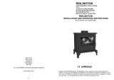
TOP FLUE EXIT
For the top outlet configuration, remove the blank-
ing plate from the hob, remove the flue spigot from
the back plate and fix it to the hob. Fix the outlet
blanking plate to back plate (see Fig. 2). Push the
flue outlet connector pipe (not supplied) into the flue
spigot and cement into place using approved fire
cement ensuring that no cement blocks the flue pas-
sageway.
Fig.1
REAR FLUE EXIT
Push the flue connector pipe (not supplied) into the
flue spigot and cement into place using approved
fire cement ensuring that no cement blocks the flue
passageway (see Fig.1).
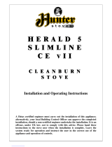
DOWN DRAUGHTS
However well designed constructed and positioned,
the satisfactory performance of the flue can be
adversely affected by down draught caused by near-
by hills, adjacent tall buildings or trees. These can
deflect wind to blow directly down the flue or create
a zone of low pressure over the terminal. A suitable
anti-down draught terminal or cowl will usually effec-
tively combat direct down blow but no cowl is likely
to prevent down draught due to a low pressure zone.
(See Fig.2)
Rear Outlet
Top Outlet

VENTILATION AND COMBUSTION AIR
REQUIREMENTS
A permanent air supply must be provided in accor-
dance with Building Regulation ADJ and BS 8303.
Please refer to Building Regulations Part J to deter-
mine the size of permanent air vent required, as fol-
lows:
Install where draft stabilizer is fitted:
Permanently open vents as below:
If design air permeability >5.0m
3
/(h.m
2
) then
300mm
2
/kW for first 5kW of appliance rated output
850mm
2
/kW for balance of appliance rated output
If design air permeability <5.0m
3
/(h.m
2
) then
850mm
2
/kW of appliance rated output (4)
Install where no draft stabilizer is fitted:
Permanently open vents as below:
If design air permeability >5.0m
3
/(h.m
2
) then
550mm
2
/kW of appliance rated output above 5kW
If design air permeability <5.0m
3
/(h.m
2
) then
550mm
2
per kW of appliance rated output (4)
Direction of wind
Direction of wind
Direction of wind
Pressure zone
Pressure zone
Suction zone
Suction zone
Pressure zone
Suction zone
Fig 2
If there is another appliance using air fitted in the
same or adjacent room, it will be necessary to
provide an additional air supply.
All materials used in the manufacture of air vents
should be such that the vent is dimensionally stable,
corrosion resistant, and no provision for closure. Air
inlet grills should be positioned so they do not
become liable to blockage.
The effective free area of any vent should be ascer-
tained before installation. The effect of any grills
should be allowed for when determining the effective
free area of any vent.
Air vents direct to the outside of the building should
be located so that any air current produced will not
pass through normally occupied areas of the room.
An air vent outside the building should not be locat-
ed less than the dimensions specified within the
Building Regulations and B.S. 8303: Part 1 from any
part of any flue terminal. These air vents must also
be satisfactorily fire proofed as per Building
Regulations and B.S. 8303: Part 1.
Air vents in internal walls should not communicate
with bedrooms, bedsits, toilets, bathrooms or rooms
containing a shower.
Air vents traversing cavity walls should include a
continuous duct across the cavity. The duct should
be installed in such a manner as not to impair the
weather resistance of the cavity.
Joints between air vents and outside walls should be
sealed to prevent the ingress of moisture. Existing
air vents should be of the correct size and unob-
structed for the appliance in use. If there is an
extraction fan fitted in adjacent rooms where this
appliance is fitted, additional air vents may be
required to alleviate the possibility of spillage of
products of combustion from the appliance/flue
while the fan is in operation. Refer to B.S. 8303 Part
1.
Where such an installation exists, a test for spillage
should be made with the fan or fans and other appli-
ances using air in operation at full rate, (i.e. extrac-
tion fans, tumble dryers) with all external doors and
windows closed.
If spillage occurs following the above operation, an
additional air vent of sufficient size to prevent this
occurrence should be installed.
4

5
Note:- If there is any work that is being carried out
that would effect the air quality supplied to the stove
such as sanding a floor or glueing linoleum etc. the
stove must be out of operation. The dust or vapours
may be a potential hazard, the air supply and local
area needs to be thoroughly ventilated before
putting the stove in operation again.
Extractor Fan
There must not be an extractor fan fitted in the same
room as the stove as this can cause the stove to
emit smoke and fumes into the room.
COMMISSIONING & HANDOVER
On completion of the installation allow a suitable
period of time for any fire cement and mortar to dry
out, when a small fire may be lit and checked to
ensure the smoke and fumes are taken from the
stove up the chimney and emitted safely to the
atmosphere. Do not run at full output for at least
24 hours.
On completion of the installation and commissioning
ensure that the operating instructions for the stove
are left with the customer. Ensure to advise the cus-
tomer on the correct use of the appliance with the
fuels likely to be used on the stove and warn them to
use only the recommended fuels for the stove.
Advise the user what to do should smoke or fumes
be emitted from the stove. The customer should be
warned to use a fire guard to BS 8423:2002 in the
presence of children, aged and/or infirm persons.
LOCATION
There are several conditions to be considered in
selecting a location for your stove.
A. Allowances for proper clearances to
combustibles of the stove and flue pipes.
B. The product must be installed on a non
combustible hearth with adequate load bearing
capacity.
C. Fluing considerations; length of flue, length of
horizontal run, flue termination.
D. Location within area to be heated.
FLOOR PROTECTION
The product must be placed on a non combustible
hearth in accordance with UK Building Regulation
part ADJ. The hearth must be suitably robust and to
the appropriate dimensions.
For free standing installations it is acceptable to
place the stove on a solid sheet of non combustible
material minimum 12mm thick, as the product will
not raise the temperature of the upper surface of the
hearth up to 100
o
C.
CLEARANCE TO COMBUSTIBLES
Side wall to stove 32” 800mm
Back wall to stove 32” 800mm
Corner 25” 635mm
Mantle clearance 25” 635mm
It is recommended that this appliance is sited next to
and on a non-combustible surface. A minimum all
round clearance of 150mm will allow air circulation
and not impede the performance of the stove. See
Fig.3.
Fig.3

6
NOTE:-
A suitable chimney (minimum profile, chimney draft, tightness, etc) is a basic condition for the
proper functioning of fireplace stoves. See professional advice before installing the stove.
Chimney values are included in the attached technical sheet. A smoke shutter or a draft regulator
should be installed for chimneys with too strong a draft. Such a draft can cause problems during
operation, e.g. intensive burning, high fuel consumption and can also lead to permanent damage to
the stove.
STOVE DIMENSIONS
Fig. 4
Note: Dimensions stated are in milimeters and may be subject to a slight +/- variation.
TECHNICAL DATA
FUEL WOOD ANCIT
Nominal Output - Room 4.8 kW 4.9 kW
Typical refuelling intervals to
obtain nominal outputs
1 Hour 1 Hour
Fuel Gas Mass Flow 4.4 g/s 3.7 g/s
Flue Gas Temp at Nominal Output 262
o
C 275
o
C
Gross Weight 105 kgs
Flue Outlet 125mm
Log Size 310mm
This appliance has been tested in accordance with BS EN 13240

7
AIR CONTROLS
The stove has two independent air controls.
1. The primary air control or spin valve. Rotate
the spin valve clockwise to close and anticlock-
wise to open. See Fig.5
2. The secondary / window wash air control. This
is located over the door on the right hand side.
See Fig.6
When the fire has established, while burning wood
the spin valve can be closed fully or less than half a
turn open. The fire can then be controlled using the
secondary air control.
When burning approved smokeless coal the sec-
ondary air control can be moved to the minimum
position. The fire can then be controlled using the
spin valve.
RECOMMENDED FUELS
This appliance has been tested using seasoned
wood logs and smokeless coal. The appliance is
suitable for intermittent operation in smoke con-
trolled areas using wood logs and smokeless coal
approved for use in smoke controlled areas.
Wood should be kept under cover and kept as dry as
possible prior to use. Wood logs of diameter less
than 80mm and no more than 310mm long are
recommended.
Do not use liquid fuels or any fuels with a Petro-coke
ingredient as this may cause the grate to overheat
resulting in damage.
RIDDLING
Riddle the fire by connecting the grate operating tool
onto the rocker connection located at the bottom
front of the stove, then gently pull and push the rock-
er arm until all dead ash has fallen through into the
ashpan. See Fig.7
RE-FUELLING
When refuelling, always refuel onto a bed of glowing
embers, riddle gently if necessary. When refuelling,
adjust the secondary air control to the fully open
position and open the spin valve 2 turns for approx-
imately 3 minutes allowing the new refuel charge to
establish combustion before adjusting the air control
to the desired setting.
Refuelling on to a low fire bed
If there is insufficient burning material in the firebed
to light a new fuel charge, excessive smoke emis-
sion can occur. Refuelling must be carried out onto
a sufficient quantity of glowing embers and ash that
the new fuel charge will ignite in a reasonable peri-
od. If there are too few embers in the fire bed, add
suitable kindling to prevent excessive smoke.
Fuel overloading
The maximum amount of wood (1.4 kilograms per
hour) should not be exceeded, overloading can
cause excess smoke.
Fig.5
Secondary/
Window Wash
Air Control
Min Max
Fig.6
Fig.7
Riddling

Operation with door left open
Operation with the door open can cause excess
smoke. The appliance must not be operated with
the appliance door left open except as directed in
the instructions.
Remember to reset the controls after refuelling.
DAMPERS / AIR CONTROLS LEFT OPEN
Operation with the air controls or appliance dampers
open can cause excess smoke. The appliance
must not be operated with air controls, appliance
dampers or door left open except as directed in the
instructions.
DE-ASHING
NOTE - DO NOT OVERFILL THE FIREBOX
Never allow the ashpan to fill more than half way as
it will cause damage to the grate. Empty the ashpan
before lighting. Always ensure that ashes have thor-
oughly cooled before removing the ashpan. Open
the fire door and remove ashpan using the operating
tool. Close the fire door. When the ash is disposed
of, replace the empty ashpan. Do not leave the fire
unattended with the fire door open, even for a
minute. See Fig.8
DISPOSAL OF ASH
Ashes should be placed in a metal container with a
tight fitting lid. The closed container of ashes should
be on a non-combustible floor or on the ground well
away from all combustible materials pending final
disposal. If the ashes are disposed of by burial in
soil or other wise locally dispersed they should be
retained in the closed container until all cinders have
thoroughly cooled.
Fig.8
Ashpan
WARNING - NEVER DISPOSE OF ASH WHEN
STOVE IS LIGHTING.
IMPORTANT - DAMAGE CAN OCCUR TO THE
FIREBED AND GRATE ASSEMBLY IF THE ASH-
PAN IS LEFT TO OVER FILL.
MAINTENANCE
CREOSOTE - Formation and Need for Removal
When some fuels are burned slowly, they produce
tar and other organic vapours, which combine with
expelled moisture to form creosote. The creosote
vapours condense in the relatively cool chimney flue
of a slow-burning fire. As a result, creosote residue
accumulates on the flue lining. When ignited cre-
osote makes an extremely hot fire.
CHIMNEY CLEANING
The chimney should be cleaned twice annually. The
chimney can be cleaned through the stove by
removing the top baffle. The flue liner should be
cleaned in accordance with manufacturers instruc-
tions. Always use a brush with plastic bristles that is
the correct size to reach all areas of the flue.
The chimney must be swept and examined for
soundness and suitability before the appliance is
installed. Remedial action should be taken if
required seeking expert advice if necessary. Where
the chimney is believed to have previously served
an open fire installation it is possible that the higher
flue gas temperature from a closed appliance may
loosen deposits that were previously firmly adhered,
with the consequent risk of flue blockage. It is there-
fore recommended that the chimney be swept a sec-
ond time within a month of regular use after installa-
tion.
8

WARNING NOTE
Properly installed, operated and maintained the
stove will not emit fumes into the dwelling.
Occasional fumes from de-ashing and re-fuelling
may occur. However, persistent fume emission is
potentially dangerous and must not be tolerated. If
fume emission does persist, then the following
immediate action should be taken:
(a) Open doors and windows to ventilate room and
then leave the premises.
(b) Let the fire out.
(c) Check for flue or chimney blockage and clean
if required.
(d) Do not attempt to relight the fire until the cause
of the fume emission has been identified and
corrected. If necessary seek expert advice.
CO ALARM
Your installer should have fitted a CO alarm in the
same room as the appliance. If the alarm sounds
unexpectedly, follow the instructions given under
“Warning Note” above.
The most common cause of fume emission is flue-
way or chimney blockage. For your own safety
these must be kept clean at all times.
IMPORTANT NOTES
Now that your stove is installed and no doubt you
are looking forward to many comforts it will provide,
we would like to give you some tips on how to get
the best results from your stove.
1. We would like if you could take some time to
read the operating instructions/hints, which we
are confident, will be of great benefit to you.
2. Do not burn fuel with a high moisture content,
such as damp or unseasoned timber.
This will only result in a build up of tar in the
stove and in the chimney and the possibility of a
chimney fire.
3. ONCE A MONTH CHECK TO ENSURE THAT
THERE IS NO BUILD UP OF SOOT OR
BLOCKAGES AT THE STOVE FLUE EXIT
BEFORE LIGHTING ESPECIALLY AFTER A
SHUT-DOWN PERIOD. THIS MAY REQUIRE
REMOVAL OFTHE TOP BAFFLE.
4. Before loading fresh fuel into the firebox, riddle
gently, this will allow better and cleaner burning.
See Re-Fuelling Section.
9
5. Never allow a build up of ashes in the ash pan,
as this may cause the grate to burn out prema-
turely.
6. Allow adequate air ventilation to ensure plenty
of air for combustion.
7. Do not burn rubbish/house hold plastic. Do not
burn manufactured timber which contains glue.
Do not burn processed or pressure treated
timber as this will create a very intense fire over
a short period of time which will damage the
appliance.
8. Clean the chimney at least twice a year.
9. Burning at a low burn rate or unseasoned timber
will stain the glass. Regular cleaning will prevent
permanent staining.
10. Keep all combustible materials a safe distance
away from the appliance, please see section for
clearances to combustion.
11. For safety reasons never leave children, elderly
or infirmed unaccompanied while stove is in use.
Use a fireguard for solid fuel appliances in
accordance with BS 8423:2002.
12. Avoid contact with appliance when in use as the
stove reaches very high operating tempera-
tures.
13. This appliance should be regularly maintained
by a competent service engineer. Use only
replacement parts recommended by AGA.
Using unauthorised parts will invalidate
your guarantee and may cause damage or
injury.
14. Do not use an aerosol spray on or near the
stove when it is alight.
AN ODOUR WILL EMIT FROM STOVE ON FIRST
FIRING, WHEN FIRE REACHES MAXIMUM
TEMPERATURE OVER A NUMBER OF HOURS
THIS ODOUR WILL SUBSIDE.
IT IS BEST ADVISED TO OPEN WINDOWS
DURING THIS PERIOD.
THIS ODOUR IS UNPLEASANT BUT NOT TOXIC.
YOU MAY WISH TO VACATE THE ROOM WHILE
THE PAINT CURES.
WARNING: THE AIR CONTROLS/DOOR HAN-
DLE WILL BECOME HOT WHEN THE STOVE
HAS BEEN IN OPERATION FOR SOME TIME,
USE THE GLOVE/TOOLS PROVIDED WHEN
REFUELLING OR ADJUSTING AIR CONTROLS.

LIGHTING
Before lighting the stove check with the installer
that the installation work and commissioning
checks described in the installation instructions
have been carried out correctly and that the
chimney has been swept clean, is sound and
free from any obstructions. As part of the stoves
commissioning and handover the installer
should demonstrate how to operate the stove
correctly.
WARNING:- The paint on the stove gets finally
cured when the stove is lit, during the first fire
the paint can soften, the doors of the stove
should be closed but not latched during the first
fire, otherwise the rope on the door can become
embedded in the paint during final curing.
IMPORTANT: The first few fires should be rela-
tively small to permit the refractory to set prop-
erly and to season the stove.
1. Before lighting the stove, ensure that any build-
up in the firebox has been removed and that the
ashpan has been emptied.
2. Open both air controls to maximum.
3. Lay some firelighters on the grate with two
handfuls of kindling. The kindling must be cut into
thin lengths and laid across each other in layers
to allow for a quick lightup. Ignite the firelighters
and close the door.
4. When the firebed has fully ignited and is starting
to die back add 3 small logs, or a small quantity
of smokeless fuel.
5. Approximately 2 minutes after adding the logs the
door can be closed, but air settings remain
un-altered.
6. When the fire from the 3 logs is dying back a
normal fuel load of approx 1.2kg is to be added to
the fire. Leave the air controls unaltered for 5
minutes to ensure the new fuel load is well alight
before moving the air controls to the desired
settings.
FIRE SAFETY
To provide reasonable fire safety the following
should be given serious consideration:
1. The installation of smoke detectors.
2. A conveniently located fire extinguisher to con-
tend with small fires resulting from burning
embers.
3. A practical evacuation plan.
4. A plan to deal with a chimney fire as follows:
a. Notify the fire department.
b. Prepare occupants for immediate evacua-
tion.
c. Close all openings into the stove.
d. While awaiting the fire department watch for
ignition to adjacent combustibles from over
head stove pipe or from embers or from
sparks from the chimney.
CO ALARMS
Building regulations require that whenever a
new or replacement fixed solid fuel or wood/
biomass appliance is installed in a dwelling a
carbon monoxide alarm must be fitted in the
same room as the appliance. Further guidance
on the installation of the carbon monoxide alarm
is available in BS EN 50202:2012 and from the
alarm manufacturers instructions.
Provision of an alarm must not be considered a
substitute for either installing the appliance
correctly or ensuring regular servicing and
maintenance of the appliance and chimney
system.
FIRE BRICK REPLACEMENT
Lift the fire fence up to remove it. Slide the bricks to
the front of the stove, lift the brick and allow the top
edge to tilt towards the centre of the stove. Remove
the brick and fit the replacement in the reverse
order.
Note:-
Stress fractures in the firebrick do not have an effect
on the combustion or the service life of the stove,
however If the metal behind the bricks becomes
exposed from a fractured brick replace immediately
as this will cause damage to the stove.
BAFFLE REMOVAL
The top Baffle is a loose item that rests in position on
top of the middle baffle and on top of a protrusion
from the back of the front casting. There are posi-
tioned stops on the two back corners to prevent it
from sliding back along the middle baffle. To remove
it, first remove one of the side bricks and slide the
baffle forward while supporting its weight. When the
position tabs are clear of the middle baffle, lift the
back edge in over the middle baffle, then
the front edge can be lowered and the baffle
removed. To replace the baffle reverse the steps
10

11
ENAMEL CLEANING
General cleaning must be carried out when the
stove is cool.
If this stove is finished in a high gloss vitreous enam-
el, to keep the enamel in the best condition observe
the following tips:
1. Wipe over daily with a soapy damp cloth,
followed by a polish with a clean dry duster.
2. For stubborn deposits a soap impregnated
pad can be carefully used on the vitreous
enamel.
3. Use only products recommended by the
Vitreous Enamel Association, these products
carry the vitramel label.
4. DO NOT USE ABRASIVE PADS OR OVEN
CLEANSERS CONTAINING CITRIC ACID
ON ENAMELLED SURFACES. ENSURE
THAT THE CLEANSER MANUFACTUR-
ERS INSTRUCTIONS ARE ADHERED TO.
GLASS
1. How to clean:
The glass will clean itself when there is sufficient
heat generated by burning fuel. If a build-up of
creosote occurs on the glass it may be due to draft
conditions, poor quality fuel or very slow burning for
a long time. Only clean glass when the stove is
thoroughly cooled. Clean with a liquid detergent
taking care not to scratch the glass with any ash
deposits.
2. Glass Replacement: (See Fig.10)
a. Open the door fully.
b. Remove the clips and carefully remove the
broken glass.
c. Clean the glass recess in the door.
d. Place the glass into the door recess and replace
the four corner clips.
e. Tighten screws.
f. Replace glass only with ceramic glass 5mm
thick.
PROLONGED PERIODS OF NON USE
If the stove is to be left unused for a prolonged peri-
od of time then it should be given a thorough clean
to remove ash and unburned fuel residues. To
enable a good flow of air through the appliance to
reduce condensation and subsequent damage,
leave the air controls fully open.
It is important that the flue connection, any appliance
baffles or throat plates and the chimney are swept
prior to lighting up after a prolonged shutdown
period.
Fig.10
Fig.9
and ensure it it resting on the protrusion in front and
that the positional stops are interlocked with the mid-
dle baffle. See Fig.9

12
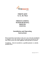
EXPLODED VIEW
1. BASE - AF0501
2. HOB - 0502
3. FRONT - 0503
4. BACK - 0504
5. LH SIDE - AF0505
6. RH SIDE - AF0506
7. DOOR - 0507B
8. BLANKING PLATE LOCKING BAR - C125Y
9. FLUE COVER BLANKING PLATE - C125
10. BACK BRICK - 0511
11. LOWER BAFFLE - 0517
12. MIDDLE BAFFLE - 0516
13. TOP BAFFLE - 0518-CR
14. AIR WASH BASE - AF0509
15. AIR WASH COVER - 0556
16. GRATE FRAME - 0514-CR
17. GRATE - AF0515-CR
18. DATA PLAQUE - CAL0101-ZJ
19. LEG - 0523
20. BACK AIR DAMPER - CA0903
21. SPIN VALVE - CAF0765
22. SPIGOT - I125
23. DOOR HINGE - CA1602
24. AIR WASH SHUTTER - CA1113-05SE
25. RIDDLING ROD - CA1401-SM05
26. PULL ROD KNOB - CA010402
27. LH SIDE BRICK - FR0512R
28. RH SIDE BRICK - FR0512L
29. FIRE DOOR HANDLE - CA0108-6
30. FIRE DOOR HANDLE AXLE - CA0101-ZH
31. SPRING WASHER - CA0502
32. DOOR CATCH - CA1505
33. ASHPAN - CA1205
34. BACK AIR PLATE - CA0901
35. FIRE FENCE - AF0520-CR
36. DOOR GLASS - CA1005B
37. DOOR GLASS CLIPS - CA1112
38. DOOR BADGE - CAL0101
39. OPERATING TOOL - CA0105

13
TROUBLE SHOOTING
SYMPTOM POSSIBLE CAUSES REMEDY
Stove Difficult To Light Air controls set incorrectly Air controls must be set to maximum
settings on initial light-up
Moisture content of fuel too high Ensure fuel is sufficiently dry
Fire Burns Too Quickly Air controls set incorrectly Adjust Air controls
Rope seals perished/worn Replace rope seals
Excessive Chimney Draught Seek professional chimney advice
Fire Burns Too Slowly/Low Heat
Output To The Room
Air controls set incorrectly Adjust Air controls
Insufficient flue draught Seek professional chimney advice
Ash buildup Do not allow ashpan to overfill
Fire Bricks Cracked Normal wear and tear Replace firebricks when they begin to
crumble as apposed to showing minor
cracks
Grate Cracked Build up of ash causing overheating Replace the grate and do not allow ash-
pan to overfill
Operation with the ash door open While the stove is in operation the door
should be closed
Burning non approved fuel Burn correct fuel
Glass Sooting Up Air wash not working Open the air wash control
Moisture content of fuel too high Ensure fuel is sufficiently dry
Insufficient flue draught Seek professional chimney advice
Air controls set to minimum settings Operate the stove at or close to the
nominal output
Smoking On Refuelling Air controls set incorrectly Air controls should be fully open prior to
refuelling
Insufficient flue draught Seek professional chimney advice
Chimney or flueways in stove have
become partially blocked
Clean the flueways in the stove. If prob-
lem persists have the chimney cleaned
by a suitable competent person
Lack of combustion air Ensure adequate sized air vent / air
supply to the room
Top baffle fitted incorrectly Consult instructions to ensure baffle fitted
in correct orientation

14
SYMPTOM POSSIBLE CAUSES REMEDY
Creosote/Tar Build-up in Firebox
and on Flue Pathways
Insufficient flue draught Seek professional chimney advice
Moisture content of fuel too high Ensure fuel is sufficiently dry
Fuel excessively dirty Use correct fuel
Air controls set to minimum settings Constant low burning can produce
excessive soot
Smells From Stove/Installation Final cure of the painted surfaces This odour is unpleasant but not toxic. It
is best advised to ventilate the room and
leave unoccupied.
Incorrect sealant used All flue Joints must be sealed with fire
cement only
Insufficient flue draught Seek professional chimney advice
Water In Base Of Stove Condensation on light up It is acceptable to have a little condensa-
tion on start up, when the fire is
established condensation should not be
present
Moisture content of fuel too high Use correct fuel

AGA,
Station Road,
Ketley, Telford,
Shropshire, TF1 5AQ,
UK
15
/