
Studio 22
Balanced Flue
Instructions for Use,
Installation and Servicing
For use in GB, IE (Great Britain and Eire)
PR1014 Issue 4 (December 2008)
IMPORTANT
Do not attempt to burn rubbish in this appliance. This appliance must only be operated with the glass door secured firmly in
position. The front casing of this appliance will become hot whilst in operation, it is therefore recommended that a suitable
guard should be used for the protection of young children, the elderly or infirm.
These instructions must be left at the property for future reference and when servicing the fire.
The Commissioning Sheet found on page 3 must be completed by the Corgi Installer.
This appliance has been certified for use in countries other than those stated. To install this appliance in these countries, it is essential to obtain the
translated instructions and in some cases the appliance will require modification. Contact Gazco for further information.

2
COVERING THE FOLLOWING MODEL:
STUDIO 22 BALANCED FLUE: 8704BFLEC P8704BFLEC
PAGE
APPLIANCE COMMISSIONING CHECKLIST 3
USER INSTRUCTIONS 4
INSTALLATION INSTRUCTIONS 9
Technical Specifications 9
Site Requirements 12
Installation 16
Commissioning 28
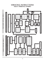
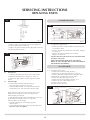
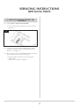
SERVICING INSTRUCTIONS 29
Fault Finding 29
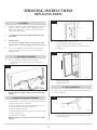
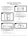
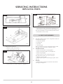
How to replace parts 31
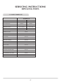
Basic spare parts list 37
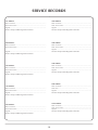
Service Records 38

3
FLUE CHECK PASS FAIL
1. Flue is correct for appliance
2. Flue flow test N/A
3. Spillage test N/A
GAS CHECK
1. Gas soundness & let by test
2. Standing pressure test mb
3. Appliance working pressure (on High Setting) mb
NB All other gas appliances must be operating on full
4. Gas rate m
3
/h
5. Does ventilation meet appliance requirements N/A
APPLIANCE COMMISSIONING CHECKLIST
Dealer .....................................................................
...............................................................................
...............................................................................
Contact No. ..............................................................
Date of Purchase .......................................................
Model No. ................................................................
Serial No. .................................................................
Gas Type ..................................................................
Installation Company ................................................
. . . . . . . . . . . . . . . . . . . . . . . . . . . . . . . . . . . . . . . . . . . . . . . . . . . . . . . . . . . . . . . . . . . . . . . . . . . . . . . .
. . . . . . . . . . . . . . . . . . . . . . . . . . . . . . . . . . . . . . . . . . . . . . . . . . . . . . . . . . . . . . . . . . . . . . . . . . . . . . . .
Engineer ...................................................................
Contact No. ...............................................................
Corgi Reg No. ............................................................
Date of Installation ....................................................
IMPORTANT NOTICE
Explain the operation of the appliance to the end user, hand the completed instructions to them for safe keeping,
as the information will be required when making any guaranteed claims.
DEALER AND INSTALLER INFORMATION
This product is guaranteed for 2 years from the date of installation, as set out in the terms and conditions of sale between Gazco and your
local Gazco dealer. This guarantee will be invalid, to the extent permitted by law, if the above Appliance Commissioning Checklist is not
fully completed by the installer and available for inspection by a Gazco engineer. The guarantee will only be valid during the second year,
to the extent permitted by law, if the annual service recommended in the Instructions for Use has been completed by a Corgi registered
engineer, and a copy of the service visit report is available for inspection by a Gazco engineer.

4
USER INSTRUCTIONS
1. GENERAL
1.1 A competent person must carry out installation and
servicing.
1.2 In all correspondence, please quote the appliance type and
serial number, which can be found on the data badge
located on a plate under the access panel, see Diagram 2,
Installation.
1.3 Do not place curtains above the fire:
You must have 300mm (1’) clearance between the fire and
any curtains at either side.
1.4 If any cracks appear in the glass panel do not use the
appliance until the panel has been replaced.
1.5 In the unlikely event the appliance is receiving interference
from other electronic devices, the handset/Control box can
be reprogrammed. Please consult your dealer if you think
this may be the case.
1.6 If, for any reason, the flue has to be removed from the
appliance, the seals must be replaced in the inner spigot.
1.7 Do not obstruct the flue terminal in any way, i.e. by
planting flowers, trees shrubs etc in the near vicinity, or by
leaning objects up against the terminal guard.
1.8 Do not use a garden sprinkler or hose near the terminal.
1.9 This product is guaranteed for 2 years from the date of
installation, as set out in the terms and conditions of sale
between Gazco and your local Gazco dealer. Please consult
with your local Gazco dealer if you have any questions. In
all correspondence always quote the Model Number and
Serial Number.
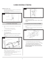
2. LIGHTING THE STUDIO
There are two ways of lighting the Studio:
• bythermostaticremotecontrol,see2A
•usingthefire’stouchpad,see2B
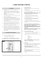
2A - THERMOSTATIC and TIMER REMOTE CONTROL
1
AR1883
Turning the Studio On
Your remote can control the gas fire from pilot ignition
through to shut down.
To turn the fire on:
• PresstheOFFbuttonandtheUPbuttonsimultaneously.
You hear several short signals.
The pilot and main burner ignite and the remote is now
in Manual Mode. In 'MANUAL MODE' you can:
• turnonthemainburner
• regulatetheflamefromhightolowandback
• turnofftheburnerleavingjustthepilotburning
In‘TEMPMODE’youcan:
• settheroomtemperaturesothethermostatinthe
remote automatically maintains that temperature
In‘TIMERMODE’thefire:
• turnsonandoffaccordingtothesettimeperiods
• automaticallyregulatestheroomtemperatureduringthe
set periods
NOTE: WHEN OPERATING THE FIRE IN TEMP OR
TIMER MODE, THE PILOT REMAINS LIT AND THE FIRE
THEN AUTOMATICALLY SWITCHES ON AT
PROGRAMMED TIMES TO BRING THE ROOM TO THE
SET TEMPERATURE WHETHER OR NOT YOU ARE IN
THE ROOM.
NEVER LEAVE ANY COMBUSTIBLE MATERIALS WITHIN 1
METRE OF THE FRONT OF THE APPLIANCE.
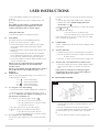
2.1 SWITCHING BETWEEN MODES
• PresstheSETbuttontochangetoManualOperation
• PressagaintochangetoTemperatureMode
• Keeppressingtorunthroughalloperatingmodes.These
are:
• MAN
• DAY
TEMP
• NIGHTTEMP
• TIMER
and back to MAN
NOTE: MAN mode can also be reached by pressing
either the UP or DOWN button
2.2 MAN MODE
•PressboththeUParrowandimmediatelypresstheOFF
button to light the appliance. You hear a click as the fire
begins the ignition process, (up to 30 seconds)
• PresstheOFFbuttontoturntheapplianceoff
INCREASING TEMPERATURE
• PresstheUParrowoncetoincreaseflameheightone
stage
• PressandholdtheUParrowtoincreasetomaximum
DECREASING TEMPERATURE
• PresstheDOWNarrowoncetodecreaseflameheight
one stage

5
USER INSTRUCTIONS
• PressandholdtheDOWNarrowtodecreaseto
minimum
At the lowest point the fire goes to 'standby mode' (only
pilot lit)
Note: While pressing a button, a symbol indicating
transmission appears on the display. The receiver
confirms transmission with an acoustic signal.
Turning the Studio Off
• PresstheOFFbuttontoextinguishthepilot
2.3 TEMP MODE
The display shows the current room temperature.
To increase or decrease the fire’s output:
• PresstheSETbuttontoselecteithertheDAYTEMP
or the NIGHT TEMP mode by briefly pressing the
SET button
• HoldtheSETbuttonuntiltheTEMPdisplayflashesand
then let go
• SetthedesiredtemperaturewiththeUPandDOWN
arrows. (Minimum temperature 5C, maximum 30C or
41F to 86F when fahrenheit is the preferred option)
• PresstheOFFbuttontostopthedisplayflashingorwait
to return to TEMP mode.
NOTE: If you set a temperature that is beneath the
current room temperature, the fire automatically
switches to OFF.
NOTE: If you would like the Night temperature control to
turn off then decrease the temperature until [---] is
displayed.
2.4 TIMER MODE
There are two programmable settings you can make over a
24 hour period, P1 and P2.
P1 +
= Start Timed Setting 1
P1 +
= End of Timed Setting 1
P2 +
= Start Timed Setting 2
P2 +
= End of Timed Setting 2
2.4.1 P1 - Program 1 for a Timed Setting
• PresstheSETbuttonuntiltheTIMERmodeisdisplayed
• HoldtheSETbutton.Thedisplaysflashesthecurrent
time for P1. While the time displayed is flashing you can
alter the hours and minutes set.
To set the time your fire first lights, change P1
•PresstheUParrowtoalterthehour
•PresstheDOWNarrowtoaltertheminutes
in 10 minute increments
•PressSETagaintomovetotheendsettingfor
P1
This is the time your Studio first shuts down:
•PresstheUParrowtoalterthehour
•PresstheDOWNarrowtoaltertheminutes
2.4.2 P2 - Program 2 for a Timed Setting
Use the same steps outlined in 2.4.1 to change the setting
for P2.
If you have already set P1 and want to alter the setting for
P2 only:
• PresstheSETbuttonuntilTIMERmodeisdisplayed
•HoldtheSETbuttonuntil the display flashes the
current time for P1
•PresstheSETbuttononceagaintoscrollpastthesettings
for P1
and P1
Withthetimestillflashing:
•PresstheUParrowtoalterthehour
•PresstheDOWNarrowtoaltertheminutes
OnceallfourtimesaresetpresstheOFFbuttonorsimply
wait to complete programming.
2.5 LOW BATTERY
“BATT” is displayed on the remote when its batteries need
replacement.
2.6 SETTING THE TIME
• SimultaneouslypresstheUPandDOWNarrowbuttons
• Presstheupbuttontosetthehourandthedownbutton
to set the minutes
• PressOFFtoreturntothemanualmodeorsimplywait
2.7 SETTING THE °C/24 HOUR OR °F/12 HOUR CLOCK
• PressOFFandthedownarrowuntilthedisplaychanges
from °C/24 hour clock to °F/12 hour clock and vice
versa.
If the remote is removed, lost or damaged, signals
transmitted to the receiver cease. Your fire will go to
standby (pilot) mode after 6 hours.
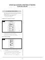
2B - TOUCH PAD CONTROL
2
AR1887
• PresstheON-OFFbuttontolighttheappliance,(upto
30 seconds)
• PresstheUPbuttontoincreasetheflameheight
• PresstheDOWNbuttontodecreasetheflameheight.At
the lowest point it goes to ‘standby mode’, (only pilot
lit)
• PresstheON-OFFbuttontoturntheapplianceoff

6
USER INSTRUCTIONS
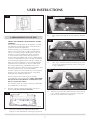
EMERGENCY SHUT OFF
If the batteries fail during use of the fire, move the switch to
theOFF(O)position,Diagram3
(ThisswitchissettobeONduringnormaloperationand
mustremainON)
3
AR1933
3. CLEANING THE STUDIO
3.1 Make sure the fire and surrounds are cool before cleaning.
Use:
• Adampclothforthepaintedframe
• Usesoapandwatertocleantheglass
3.2 Opening the Glass Door
3.2.1 Steel Frame only
[If fitted with a Steel Frame, this needs to be removed
first:
• Lifttheframeupwardsoffitsfoursupportbrackets,
Diagram 4
4
AR2136
3.3 All models
Using the allen key provided to release the upper and lower
catches on the right side of the door:
• Slidetheallenkeyintothegapbetweenthedoorand
frame and locate the catch of the upper lock
• PushtheallenkeyDOWN
• Slidetheallenkeyintothegapandlocatethelowerlock
• PushtheallenkeyUP
5
AR2119
AR2119
• Openthedooroutwards
When closing the door ensure the door catches are fully
engaged.
4. CHANGING THE STUDIO BATTERIES
The appliance batteries are located behind the wall switch
plate.
• Undothetwoscrewssecuringthewallswitchandplate
and remove, Diagram 6
6
AR1887
• CorrectlypositionthefournewAAsizebatteries
• Re-assemblethebatteryholderasshowninDiagram7
• Ensurethetouchpadcableistuckedtotheleftonfitting
the wall plate back onto the wall, Diagram 7
PLEASE ENSURE NO WIRES ARE TRAPPED BEFORE
REPLACING THE WALL PLATE. THE TOUCH PAD LEAD
IS EASILY DAMAGED.

7
USER INSTRUCTIONS
7
AR1932
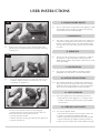
5. ARRANGEMENT OF FUEL BED
ADVICE ON HANDLING AND DISPOSAL OF FIRE
CERAMICS
The fuel effect and side panels in this appliance are made
from Refractory Ceramic Fibre (RCF), a material which is
commonly used for this application.
Protective clothing is not required when handling these
articles, but we recommend you follow normal hygiene
rules of not smoking, eating or drinking in the work area
and always wash your hands before eating or drinking.
To ensure that the release of RCF fibres are kept to a
minimum, during installation and servicing a HEPA filtered
vacuum is recommended to remove any dust accumulated
in and around the appliance before and after working on it.
Whenservicingtheapplianceitisrecommendedthatthe
replaced items are not broken up, but are sealed within
heavy duty polythene bags and labelled as RCF waste.
RCFwasteisclassedasstable,non-reactivehazardouswaste
and may be disposed of at a licensed landfill site.
Excessive exposure to these materials may cause temporary
irritation to eyes, skin and respiratory tract; wash hands
thoroughly after handling the material.
After cleaning the fire or replacing parts, carefully
re-assembletheceramiccomponents.WHEN THE EMBERS
ARE PLACED ON THE BURNER IT IS IMPORTANT THEY
DO NOT COVER ANY PORTS!
The fuel bed is made up of embers and 6 logs, identifiable
by moulded letters on their base:
5.1 Place the embers around the burner holes as shown in
Diagram 8. Do not cover any of the holes.
8
AR2120
5.2 PlaceLogAontothetwostudsontheburnerskin,
Diagram 9, with charred effect of the log facing forward.
9
AR2121
A
5.3 PlaceLogBontheledgeattherearofthefire,Diagram
10.
10
AR2122
A
B
5.4 PlaceLogCsothatthebackendsitsinthegrooveinthe
rearofLogBandthefrontleftrestsinthecut-outgroove
inLogA,Diagram11.
11
AR2123
A
B
C
5.5 PositionLogDsothattheunderneathrestsinthegrooveof
LogA,andthetriangulargrooveinthebaseofLogDfits
into the corner of the burner, Diagram 12.

8
6. FLAME FAILURE DEVICE
6.1 This is a safety feature incorporated on this appliance which
automatically switches off the gas supply if the pilot goes
out and fails to heat the thermocouple.
7. RUNNING IN
7.1 ThesurfacecoatingonthemetalusedinyourGAZCOfire
will "burn off" during the first few hours of use producing a
harmless and temporary odour. This will disappear after a
short period of use. If the odour persists, ask your installer
for advice.
8. SERVICING
8.1 The fire must be serviced every 12 months by a qualified
Gas Engineer. In all correspondence always quote the
Model number and the Serial number which may be found
on the data badge.
9. VENTILATION
9.1 Any purpose provided ventilation should be checked
periodically to ensure that it is free from obstruction.
10. INSTALLATION DETAILS
10.1 Your installer should have completed the commissioning
sheet at the front of this book. This records the essential
installation details of the appliance. In all correspondence
always quote the Model number and Serial number.
11. HOT SURFACES
11.1 Parts of this appliance become hot during normal use.
• Regardallpartsoftheapplianceasa‘workingsurface’
• Provideasuitablefireguardtoprotectyoungchildren
and the infirm
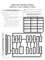
12. FIRE WILL NOT LIGHT
12.1 If you cannot light the Studio:
• CheckthattheemergencyshutoffswitchisintheON
(1) position, see Section 2, Emergency Shut Off
•Checkandchangethebatteriesintheremotehandset
• Checkandchangetheappliancebatteries,Section 4.
Consult your Gazco dealer if the Studio still does not light.
12
AR2124
A
D
5.6 PutthegrooveinthebaseofLogEintotheindentonthe
rightofLogA.TheleftbranchrestsontheupperendofLog
C, Diagram 13.
13
AR2125
A
E
5.7 LogFrestsagainstLogBatitsfarrightend,betweenLog
Bandthesidepanel.ThefrontendofLogFsitsonthe
front panel, see Diagram 14
14
AR2126
B
F
You must ensure the door catches are fully engaged:
• Slidetheallenkeyintothegapbetweenthedoorand
frame and locate the catch of the lower lock
• PushtheallenkeyDOWN
• Slidetheallenkeyintothegapandlocatetheupperlock
• PushtheallenkeyUP
USER INSTRUCTIONS

9
INSTALLATION INSTRUCTIONS
TECHNICAL SPECIFICATION
COVERING THE FOLLOWING MODELS:
STUDIO 22 BF: 8704BFLEC P8704BFLEC
Model Gas
CAT.
Gas Type Working
Pressure
Nox
Class
Aeration Injector Gas Rate
m
3
/h
Input kW (Gross) Country
High Low
8704BFLEC
I
2H
Natural Gas (G20) 20 mbar 4 5 x 16 mm 530 0.715 7.5 3.75 GB, IE
P8704BFLEC
I
3P
Propane (G31) 37 mbar
16 x 24 (1)
6 x 15 (1)
200 0.254 7 3.6 GB, IE
REAR EXIT WALL THICKNESS
Min 200 mm - Max 550 mm
EfciencyClassII
Flue Outlet Size Ø 150mm
Flue Inlet Size Ø 100mm
Gas Inlet Connection Size Ø 8mm
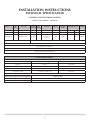
RESTRICTOR REQUIREMENT
VERTICAL & HORIZONTAL FLUE SPECIFICATIONS
Vertical Flue Height from Top of Appliance Horizontal Length Restrictor Size
200 mm 500 mm No restrictor
500 mm 1000 mm No restrictor
1000 mm to 1500 mm 250 mm to 5000 mm Ø 70 mm
1510 mm to 3000 250 mm to 5000 mm Ø 60 mm
TOP EXIT - VERTICAL INCLUDING OFFSET
Vertical Flue Height from Top of Appliance Restrictor Size
3000 mm up to 4990 mm Ø 52 mm
5000 mm up to 10,000 mm Ø 47 mm

10
INSTALLATION INSTRUCTIONS
TECHNICAL SPECIFICATION
This appliance has been certified for use in countries other than
those stated. To install this appliance in these countries, it is
essential to obtain the translated instructions and in some cases
the appliance will require modification. Contact Gazco for further
information.
PACKING CHECKLIST
Qty Description Fixing Kit containing:-
1LogSet 1 x Instruction Manual
4xWoodScrews
4 x Rawl Plugs
1 x Handset
4 x AA cell batteries
1 x 9V cell batteries
1xWallbox
1 x Touch pad/wall plate
1 x Battery holder
1 x Foam seal
AR2114

11
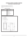
INSTALLATION INSTRUCTIONS
TECHNICAL SPECIFICATION
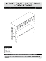
Steel Frame Dimensions
Dimension: Size (mm)
A
1350
B 675
C 846
D 320
E 177
F 237
G 25
ProlFrameDimensions
Dimension: Size (mm)
A
1036
B 510
C 940
D 414
E 48
F 48
G 12.5
Bauhaus Frame Dimensions
Dimension: Size (mm)
A
1050
B 524
C 940
D 414
E 55
F 55
G 28
2
Steel
Profil
Bauhaus
AR1550
E D
F
C
A
B
G
E
D
F
C
A
B
E
D
F
C
A
B
G

12
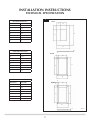
INSTALLATION INSTRUCTIONS
SITE REQUIREMENTS
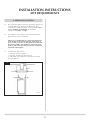
Note: This appliance must only be installed with the flue
supplied.
You must adhere to the following:
1.1 The flue must be sited in accordance with BS5440: Part 1
(latest edition). See Diagram 1.
1.2 Fit a guard to protect people from any terminal less than 2
metres above any access such as level ground, a balcony or
above a flat roof.
1.3 All vertical and horizontal flues must be securely fixed and
fire precautions followed in accordance with local and
national codes of practice.
1.4 A restrictor may be required. Refer to Technical
Specifications on page 9.
1.5 Three types of flue termination are possible, rear, top exit
horizontal and top exit vertical. To measure for a top exit
horizontal terminal:
• Decideontheterminalposition
• Measuretheheightfromthetopoftheappliancetothe
centre of the required outlet.
For minimum and maximum flue dimensions see Section 2,
Flue Options.
• Allowenoughroomeitheraboveortothesideofthe
appliance to assemble the flue on top
• Assembleahorizontalflueinthefollowingorder:
-Verticalsection
-90°elbow
-Horizontalplusterminal
• Supporttheopeningofamasonryinstallationwitha
lintel.
1.7 Onlythehorizontalterminalsectioncanbereducedinsize.
1. FLUE AND CHIMNEY REQUIREMENTS
1
UK Dimensions

13
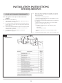
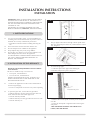
2. FLUE OPTIONS
REAR EXIT (8708)
• Cuttolengthasrequiredonsite
1
AR0630
200 mm min
500 mm max
Guard Supplied.
TOP EXITS
2.1 TOP FLUE UP & OUT KIT (8534)
This flue is vertical from the top of the appliance then
horizontally out. (See Diagram 2). The basic kit comprises:
1 x 200mm vertical length
1 x 500mm terminal length (cut to length on site)
1 x 90° elbow
1 x wall plate
1 x 70mm restrictor
1 x 60mm restrictor
2
AR1671
NOTE:
The start of the bend to the centre line of horizontal flue
is 170mm.
The centre line of vertical flue to end of bend is 220mm.
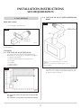
INSTALLATION INSTRUCTIONS
SITE REQUIREMENTS
2.2 TOP FLUE UP & OUT WITH ADDITIONAL
BEND
3
AR1672
WhenA=1.0to1.499metesB&C=1.0metres
maximum
WhenA=1.499metresto3.0metresB&C=4.0
metres maximum
Any additional bend may be used on the horizontal section
(either 45° or 90°), but the overall horizontal flue run will
be reduced. Refer to Diagram 3.

14
INSTALLATION INSTRUCTIONS
SITE REQUIREMENTS
2.3 TOP FLUE VERTICAL KIT (8524/8524AN)
Vertical from the top of the appliance (See Diagram 4).
4
AR1673
A minimum vertical rise 3m (9’10") to a maximum 10m
(32’10"). The basic kit comprises:
2 x 1m lengths
1 x 1m terminal length
1 x 52mm restrictor
1 x 47mm restrictor
1 x 60mm restrictor
Extra lengths may be added from the list below.
2.4 TOP FLUE VERTICAL OFFSET KIT
(8530/8530AN)
Used with kit 8524. A minimum rise of 500mm (19
1
/
2
) is
required to the first bend. See Diagram 1C.
2.5 EXTRA FLUE LENGTHS
All flue components are 150mm diameter (6")
NOMINAL ACTUAL STAINLESS ANTHRACITE
LENGTH LENGTH FINISH FINISH
200mm 140mm 8527 8527AN
500mm 440mm 8528 8528AN
1000mm 940mm 8529 8529AN
40° Bend N/A 8507 8507AN
90° Bend N/A 8508 8508AN
NOTE: Carefully consider:
a) Terminal positions
b) Flue supports
c) Weatherproofing
d) Fire precautions
For all the above options, you must conform to local and
national codes of practice .
3. GAS SUPPLY
THIS APPLIANCE IS INTENDED FOR USE ON A GAS
INSTALLATION WITH A GOVERNED METER.
3.1 Before installation, ensure that the local distribution
conditions (identification of the type of gas and pressure)
and the adjustment of the appliance are compatible.
3.2 Ensure the gas supply delivers the required amount of gas
and is in accordance with the rules in force.
3.3 You can use soft copper tubing on the installation and soft
soldered joints outside the appliance and below the fire.
3.4 A factory fitted isolation device is part of the inlet
connection; no further isolation device is required.
3.5 All supply gas pipes must be purged of any debris that may
have entered prior to connection to the appliance.
3.6 The gas supply enters through the silicone panel located on
the bottom or rear of the outer box:
• Slitwithasharpknifepriortopassingthesupplypipe
through.
3.7 The gas supply must be installed in a way that does not
restrict the removal of the appliance for servicing and
inspection.
4. VENTILATION
4.1 This appliance requires no additional ventilation.

15
INSTALLATION INSTRUCTIONS
SITE REQUIREMENTS
5. APPLIANCE LOCATION
5.1 Please note this appliance has been specifically designed for
studwork applications although installation into other
constructions, including masonry, is entirely feasible. There
are two methods of installation, see Installation
Instructions 3.2 Frame, 3.3 Edge
5.2 Thisappliancemuststandonanon-combustiblehearth/
platform that is at least 12mm thick.
NOTE: It is recommended you construct the back panel
of the fireplace from natural materials cut into three or
more sections to prevent cracking. Resin-based materials
may not be suitable. This appliance is an effective heat
producer and attention must be paid to the construction
and finish of the fireplace.
5.3 A combustible shelf must be:
• maximum150mmindepth
• minimum,400mmhighabovethefire
A combustible side wall must be a minimum of 150mm
from the appliance.
5
AR2077

16
INSTALLATION INSTRUCTIONS
INSTALLATION
IMPORTANT: REFERTODATABADGEANDTECHNICAL
SPECIFICATIONATTHEFRONTOFTHEMANUALTO
ENSURETHEAPPLIANCEISCORRECTLYADJUSTEDFOR
THEGASTYPEANDCATEGORYAPPLICABLEINTHE
COUNTRYOFUSE.
FORDETAILSOFCHANGINGBETWEENGASTYPES
REFERTOSECTION 10, SERVICING,‘REPLACINGPARTS’.
1. SAFETY PRECAUTIONS
1.1 For your own and other’s safety, you must install this fire
according to local and national codes of practice. Failure to
install the fire correctly could lead to prosecution:
• Readtheseinstructionsbeforeinstallingandusingthis
fire.
1.2 These instructions must be left intact with the user.
1.3 Do not attempt to burn rubbish on this appliance.
1.4 Keepallplasticbagsawayfromyoungchildren.
1.5 Do not place any object on or near to the appliance and
allow adequate clearance above the appliance.
IFTHEAPPLIANCEISEXTINGUISHEDORGOESOUTIN
USE,WAIT3MINUTESBEFOREATTEMPTINGTO
RELIGHTTHEAPPLIANCE.
2. INSTALLATION OF THE APPLIANCE
REFER TO THE SITE REQUIREMENTS SECTION FOR ALL
FLUE OPTIONS.
This stove is suitable for top or rear flue exit.
• Fortopexit,readSection 8.2
• Forrearflueexit,readSection 8.1
THEREISANOPTIONALDUCTKIT,CODENo.8572
WHICHCANBEFITTEDATTHESAMETIMEASTHE
APPLIANCEINSTALLATION.
2.1 • Removetheappliancefromthecartonanddiscardall
unnecessary packaging
• Ensurenocomponentsarethrownawaywhenunpacking
2.2 To open the glass door, use the allen key provided:
• Slidetheallenkeyintothegapbetweenthedoorand
frame and locate the catch of the upper lock
• PushtheallenkeyDOWN
• Slidetheallenkeyintothegapandlocatethelowerlock
• PushtheallenkeyUP
1
AR2119
AR2119
• Openthedooroutwards
2.3 The gas supply enters the fire through a silicon panel on the
floor or in the back panel of the fire, underneath the control
unit, Diagram 2
2
AR2130
AR2130
2.4 To access the gas pipe:
• Undotheclipsontheupperinsideholdingthe
vermiculite side panels in place, Diagram 3
3
AR2127
Vermiculite side panel
• Removethetwosidepanelsandbackpanelandputto
one side
• Ensurethebackpanelissupportedwhenremovingthe
side panels
TAKE CARE WHEN HANDLING THE VERMICULITE
PANELS, THEY ARE FRAGILE.

17
INSTALLATION INSTRUCTIONS
INSTALLATION
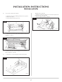
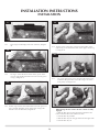
2.5 You can now remove the burner:
• Undothefourscrewsholdingtheburnertrayinplace
• Removetheburner
• Lifttheleft-handsideupandout
4
AR2117
2.6 • Undothetwoscrewsintherearairbaffletoremoveit,
Diagram 5, arrow A
5
AR2116
A
A
B
• Removethetwoscrewsholdingtheaccesspanelin
place, Diagram 5, arrow B
2.7 • Undothe13screwsfixingthecontrolunitinplace
6
AR2135
Withallscrewsremoved:
• Slidethecontrolunittothelefttocleartheinjectorand
pilot pipework at the right side
• Lifttheright-handsideupandout
7
AR2128

18
INSTALLATION INSTRUCTIONS
INSTALLATION
3. STUD WORK INSTALLATION
THERE ARE THREE TYPES OF INSTALLATION INTO
STUDWORK DESCRIBED IN THE FOLLOWING PAGES:
1) FOR STUDIO 22 WITH EITHER THE STEEL, PROFIL
OR BAUHAUS FRAME, SEE SECTION 4
2) FOR AN INSTALLATION WHERE THE STUDIO 22 SITS
FLUSH TO THE FINISHED 'EDGE' OF THE WALL, SEE
SECTION 5
3) FOR A FURTHER 'EDGE' INSTALLATION PROVIDING
A COOL WALL ABOVE THE APPLIANCE TO ALLOW
CUSTOMERS TO HANG PICTURES ETC., SEE SECTION
6
3.1
DISTANCE TO COMBUSTIBLE MATERIAL
COMBUSTIBLE PARTS OF THE STUDWORK MUST BE
KEPT BEYOND THE MINIMUM DIMENSIONS SHOWN
IN DIAGRAM 8. EVEN IF THE FRAMEWORK IS
PROTECTED BY NON-COMBUSTIBLE MATERIAL, YOU
MUST MAINTAIN THESE DIMENSIONS.
8
AR2077
3.2 DO NOT PACK THE VOID AROUND OR ABOVE THE
APPLIANCE WITH INSULATION MATERIALS SUCH AS
MINERAL WOOL.
3.3 THE VOID BUILT FOR THE APPLIANCE MUST BE
VENTILATED TO PREVENT A BUILD-UP OF HEAT. IF THE
VOID IS SEALED, THEN YOU MUST FIT VENTS AT BOTH
LOW AND HIGH LEVELS OF APPROXIMATELY 50CM
2
EACH. THESE VENTS MUST TAKE COLD AIR FROM THE
ROOM AND RETURN WARM AIR BACK INTO THE
ROOM
3.4 AN ACCESS HATCH MUST BE LEFT IN THE SIDE OF THE
CHIMNEY BREAST FOR FUTURE SERVICING AND
INSPECTION OF THE FLUE AND APPLIANCE.
4. STUDWORK INSTALLATION FOR
STUDIO WITH FRAMES
• Buildthestudworkchimneybreastandenclosuresto
the desired size to include the protected platform at the
required height.
•Linetheaperturefortheappliancewith12mmthicknon-
combustible material as shown, Diagram 9
9
AR1902
• Ensuretheclearancesaremaintained,seeDiagram8
• Sitetheapplianceanddecideonfluerequirements
• Cutaholefortheflueexit-seeInstallation
Instructions, Flue Assembly
• Providegasservicesintotheappliancevoidontheleft-
hand side
Because no combustible material can be used above the
fire, we provide a support bar:
• Markoutthepositiontofitthesuppliedtopsupportbar
into the studwork at the correct height. This bar needs to be
recessed into the studwork, Diagram 10
10
AR1903
Detail A

19
INSTALLATION INSTRUCTIONS
INSTALLATION
• Fitthesupportbarintothestudworkatthecorrect
height, Diagram 11.
11
AR1904
• Attachthe4framefixingbracketstothefirebyplacing
the top part of the bracket through the slots
• Pushthebracketflatagainstthepanel,thenslidedown
to the stop, see Diagram 12
12
AR1913
• Fixfoamsealtotheouterflangeofthefire,Diagram13
13
AR1913b
• Positionthefire
• Fitnon-combustibleboardtothestudworkaroundthe
fire. This should extend a minimum of 400mm above the
appliance and at least 50mm to the sides of the appliance
(from the outer box, not the flanges).
• Applyplasterboardtotheremainderofthestudwork
• Securethefirebacktothestudworkusingfourscrews
through flange, bracket, support bar
• Applyaplasterfinishtothefrontofthechimneybreast
Slips
Because of the high temperatures this fire achieves, it is advisable
to use marble slips or similar material between the appliance and
the plasterboard.
Never use a one-piece slip because expansion (even cracking)
can occur.
Note: If a slip is used, longer screws are needed to secure the
appliance.
To finish the installation:
• Connectthewallboxandbatteriesfollowinginstruction
in Section 7 below
• Connect:
- thefluesystem(seeInstallation, Flue Assembly)
-andgasservices(seeInstallation Section 9) using the
opening in the side of the chimney breast for access.
After commissioning:
• Finishthesidesofthechimneybreast,Diagram14
14
AR1905
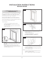
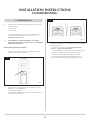
5. STUDWORK FOR STUDIO EDGE
INSTALLATION KIT
ThereisanoptionalStudio22EdgeInstallationKitavailablefor
installing the fire without a frame: Studio 22 BF Code No.
8727BFEK22.Thisconsistsoffourmetalbracketssothatyoucan
create a flush finish to the "edge" of the appliance.
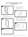
Using the installation kit:
• Fitthefourmetalbracketsofthekittothefire:
•Fitthesidestotheapplianceandsecureusingnutsand
washers provided
•Attachthetopandbottommetalbracketstothetop
and bottom flanges of the appliance using nuts
and washers provided, see Diagram 15

20
INSTALLATION INSTRUCTIONS
INSTALLATION
15
AR2134
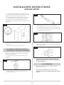
• Putverticalstudworkatminimumclearancetothesideof
the fire (50mm)
•Securetotheverticalstudworkthroughtheholesinthe
metal brackets fitted to the fire, Diagram 16
Thekithasbeendesignedsothatnon-combustibleboard
can be taken right up to the edge of the four brackets,
Diagram 17
16
AR2133
17
AR2085
Build the studwork chimney breast to the desired size:
• Ensureallclearancestocombustiblematerialare
maintained, Section 3, 3.1 above
• Decideonfluerequirements
• Cutaholefortheflueexit-seeInstallation
Instructions, Flue Assembly
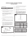
18
AR1902
• Fitnon-combustibleboardtothestudworkaboveandto
the sides of the fire. This should extend a minimum of
400mm above the appliance and a minimum of 50 mm to
each side
• Fitplasterboardtotheremainingchimneybreastfront
• Connectthefluesystemandgasservicesusingthe
opening in the side of the chimney breast for access
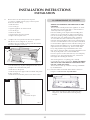
After commissioning, finish the sides of the chimney breast,
Diagram 19
19
AR1911
Detail A
A
•Applyaplasterfinishtothechimneybreast
Page is loading ...
Page is loading ...
Page is loading ...
Page is loading ...
Page is loading ...
Page is loading ...
Page is loading ...
Page is loading ...
Page is loading ...
Page is loading ...
Page is loading ...
Page is loading ...
Page is loading ...
Page is loading ...
Page is loading ...
Page is loading ...
Page is loading ...
Page is loading ...
Page is loading ...
-
 1
1
-
 2
2
-
 3
3
-
 4
4
-
 5
5
-
 6
6
-
 7
7
-
 8
8
-
 9
9
-
 10
10
-
 11
11
-
 12
12
-
 13
13
-
 14
14
-
 15
15
-
 16
16
-
 17
17
-
 18
18
-
 19
19
-
 20
20
-
 21
21
-
 22
22
-
 23
23
-
 24
24
-
 25
25
-
 26
26
-
 27
27
-
 28
28
-
 29
29
-
 30
30
-
 31
31
-
 32
32
-
 33
33
-
 34
34
-
 35
35
-
 36
36
-
 37
37
-
 38
38
-
 39
39


Ask a question and I''ll find the answer in the document
Finding information in a document is now easier with AI
Related papers
-
Stovax PR0919 User manual
-
-
-
-
-
-
-
-
-
Other documents
-
 crystal fires Chicago Installation & Servicing Book
-
ARMAC MARTIN LM5103 Operating instructions
-
 Vision Fires Vision E-Line Electric Fires User manual
-
AGA Classic Range Gas Owner's manual
-
 Yeoman PR1145 User manual
-
 Yeoman 8455 User manual
-
Valor GV60 Owner's manual
-
Pyle PSIP24 User manual
-
Paragon P10 Instruction For User, Installation & Servicing
-
 Argos 239/2352 Assembly Instructions Manual


