
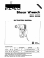
Shear Wrench
Dimensions
(L
x
W
x
H)
241
mm
x
84
mm
x
246
mm
(9-112''
x
3-5/16"
x
9-11/16")
249
mm
x
84
mm
x
252 mm
19-13/16"
x
3-5/16"
x
9-15/16")
Bolt size
Max.
torque
No
load
speed
IRPMI
26
Model
6920NB
5/8".
314"
60
kg.m
6922N8
5/13",
34".
7/8"
82
kg,m
(A4901 (434 Ibs,ftl
18
(A4901
1593
Ibs,ft)
MODEL
6920NB
MODEL
6922NB
Net
weight
4.3 kg
(9.5
lbsl
4.8 kg
(10.6
Ibsl
INSTRUCTION MANUAL
DOUBLE
lNSULATlON

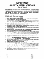
IMPORTANT
SAFETY
INSTRUCTIONS
(For
All
Tools)
WARNING:
WHEN USING ELECTRIC TOOLS, BASIC SAFETY
PRECAUTIONS SHOULD ALWAYS BE FOLLOWED TO REDUCE
THE
RISK
OF
FIRE,
ELECTRIC SHOCK, AND PERSONAL
INJURY,
INCLUDING THE FOLLOWING:
READ
ALL INSTRUCTIONS.
1.
KEEP WORK AREA CLEAN. Cluttered areas and benches invite injuries.
2. CONSIDER WORK AREA ENVIRONMENT. Don't use power tools
in
damp
or
wet locations. Keep work area well
lit.
Don't expose power tools to rain.
Don't use tool
in
presence of flammable liquids or gases.
3. KEEP CHILDREN AWAY. All visitors should be kept away from work area.
Don't let visitors contact tool or extension cord.
4.
STORE IDLE
TOOLS.
When not
in
use, tools should
be
stored
in
dry, and high
or locked-up place
-
out of reach of children.
5.
DON'T FORCE TOOL.
It
will do the
job
better and safer at the rate for which
it
was intended.
6.
USE RIGHT TOOL. Don't force small tool or attachment to do the
job
of a
heavy-duty tool. Don't use tool for purpose not intended.
7.
DRESS PROPERLY. Don't wear loose clothing or jewelry. They can be caught
in
moving parts. Rubber gloves and non-skid footwear are recommended
when working outdoors. Wear protective hair covering to contain long hair.
8.
USE SAFETY GLASSES.
Also
use face or dust mask if cutting operation is
dusty.
9.
DON'T ABUSE CORD. Never carry tool
by
cord or yank
it
to disconnect from
receptacle. Keep cord from heat, oil, and sharp edges.
10.
SECURE WORK. Use clamps or
a
vise to hold work. It's safer than using
your
hand and it frees both hands
to
operate tool.
11.
DON'T OVERREACH. Keep proper footing and balance at all times.
12.
MAINTAIN
TOOLS
WITH CARE. Keep tools sharp and clean for better and
safer perform.ance. Follow instructions for lubricating and changing acces-
sories. Inspect tool cords periodically and if damaged, have repaired
by
autho-
rized service facility. Inspect extension cords periodically and replace if
damaged. Keep handles dry, clean, and free from oil and grease.
13. DISCONNECT TOOLS. When not
in
use, before servicing, and when chang-
ing accessories, such as blades, bits, cutters.
2

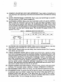
0-25
1
26
-
60
Ampere Rating
More
Not
More
Then Then
51
-
100
101
-
150
~
0-
6
6-
10
10
-
12
12
-
16
AWG
18 16
16
14
16
14
Not
Recommended
17.
OUTDOOR USE EXTENSION CORDS. When tool is used outdoors,
use
only
18.
STAY ALERT. Watch what you are doing, use common sense. Don't operate
19.
CHECK DAMAGED PARTS. Before further use of the tool, a guard
or
other
extension cords intended for use outdoors and
so
marked.
tool when you are tired.
20.
21.
22.
part that is damaged should be carefully checked to determine that
it
will
operate properly and perform its intended function. Check for alignment of
moving parts, binding of moving parts, breakage of parts, mounting, and
any other conditions that may affect its operation. A guard
or
other part
that is damaged should be properly repaired or replaced by an authorized
service center unless otherwise indicated elsewhere
in
this instruction
manual. Have defective switches replaced by authorized service center. Don't
use tool
if
switch does not turn
it
on and off.
GUARD AGAINST ELECTRIC SHOCK. Prevent body contact
with
grounded
surfaces. For example; pipes, radiators, ranges, refrigerator enclosures.
REPLACEMENT PARTS. When servicing, use only identical replacement parts.
POLARIZED PLUGS. To reduce the risk of electric shock, this equipment has
a polarized
plug
[one blade is wider than the other). This plug
will
fit
in
a
polarized outlet only one way. If the
plug
does not fit fully
in
the outlet,
reverse the
plug.
If
it
still does not fit, contact a qualified electrician to install
the proper outlet. Do not change the plug
in
any way.
3

VOLTAGE WARNING: Before connecting the tool to a power source (receptacle,
outlet, etc.) be sure the voltage supplied is the same as that specified on the
nameplate of the tool.
A
power source with voltage greater than that specified
for the tool can result
in
SERIOUS INJURY to the user
-
as
well as damage to
the tool. If
in
doubt,
DO
NOT PLUG IN THE
TOOL.
Using a power source with
voltage less than the nameplate rating is harmful to the motor.
,
ADDITIONAL SAFETY RULES
1.
Always be sure you maintain good balance and firm footing.
2.
Use care and common sense when disposing of sheared bolt tips.
Be sure no one is below when using the tool in high or elevated locations.
Falling tips from high locations or scattered tips can cause severe injury.
SAVE THESE INSTRUCTIONS.
4

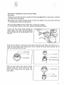
Removing
or
installing
the
outer and inner
sleeves
CAUTION
:
*Always be sure that the tool
is
switched off and unplugged before removing or installing
Be
careful not to allow foreign matter
to
enter the insides of the tool when removing
the outer and inner
sleeves.
or installing the outer and inner
sleeves.
The outer
sleeve
M20
and
inner
sleeve
3/4"
are factory-installed.
If you need other
sizes
for your work, replace the
sleeves
as
follows.
Inner sleeve spring
Loosen the
two
screws while holding the
outer
sleeve.
The outer and inner
sleeves
will
be pushed up by the springs built into
the tool.
I
=-
\\
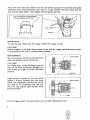
Press the pin down to remove the inner
sleeve
from the outer
sleeve.
Be
careful not to
drop the inner
sleeve
when removing
it.
Do
not remove the inner
sleeve
spring, tip rod
and tip rod spring from the tool.
1-
Inner sleeve
Hold the inner
sleeve
with the pin facing
upward.
Place
the outer
sleeve
over the
inner
sleeve.
Press the pin to secure
the
inner
sleeve.
Outer
sleeve
in
sleeve
5

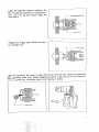
Insert the outer and inner
sleeves
into the tool while rotating the inner
sleeve
alternately
clockwise and counterclockwise until there
is
no gap between the outer
sleeve
and the
tool.
See the figure below. Then tighten the
two
screws securely.
Switch action
To start
the
tool, simply pull the trigger. Release the trigger to stop.
CAUTION
:
Before plugging in
the
tool, always check
to
see
that the trigger switch actuates proper-
ly and returns to the
“OFF”
position when released.
Bolt
installation
Slip the tool onto
the
bolt
so
that the inner
sleeve
completely covers
the
bolt
tip.
CAUTION
:
Be
careful when fitting the
sleeve
onto the
bolt tip.
Striking the tip can damage it
so
that it will no longer fit inside the
sleeve
properly.
Keep forward pressure on the tool while
sliding
it
further forward until the outer
sleeve
fits completely over the nut. If
the
tool
fails to fit completely over the nut,
twist the tool slightly right and left while
pushing forward.
sleeve
Pull the trigger switch. The outer
sleeve
turns to begin tightening the nut.
6

When
the
specified torque
is
attained, the
Il
'
bolt tip will be sheared at its notched por-
tion. The bolt tip will remain inside the
inner
sleeve.
tion
-
-
Release
the trigger and withdraw the tool
in
a
straight line.
__Outer sleeve
Press the tip ejector (tip lever) to eject the bolt tip from the tool. Catch the sheared bolt
tips to prevent them from falling dangerously below. Keep the tips
off
of the ground,
floor, walkways, etc. to prevent injury from tripping or falling.
Bolt
tip
7
,
,
.
.
.
.
.
. .
.
.
.
..
,
.
.
.I
I
..
..:..

.. ..
..
....
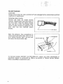
Replacing carbon brushes
Remove and check the carbon brushes
regularly. Replace when they wear down to
the limit mark. Keep the carbon brushes
clean and free to slip in
the
holders. Both
carbon brushes should be replaced
at
the
same time. Use only identical carbon
brushes.
MAINTENANCE
CAUTION
:
Always be sure that the tool
is
switched off and unplugged before attempting to perform
inspection or maintenance.
-
Open the protector. Use
a
screwdriver to
remove the brush holder caps. Take out the
worn carbon brushes, insert the new ones
and secure the brush holder caps.
Brush
holder
c
To
maintain product SAFETY and RELIABILITY, repairs, any other maintenance or
adjustment should be performed by Makita Authorized or Factory Service Centers,
always using Makita replacement parts.
8

Fob
-
10-'94 US
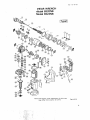
SHEAR WRENCH
Model
6920NB
Model
6922NB
Note: The switch, noise suppressor and other part configuratlons
may differ from country
10
country
9

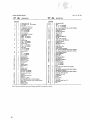
MODEL
6920N8. 6922118
ILLM
,&
DESCRIPTION
..
F.b-10--'84
US
$.&
DESCRlPTlDN
MA
I
2
3
4
5
6
7
8
9
IO
I1
I2
13
14
15
16
17
I0
19
20
21
22
23
24
25
26
21
28
29
30
31
32
33
34
35
36
31
-
"rE
I
1
I
I
I
I
I
1
I
1
4
4
4
I
4
2
4
4
4
4
1
4
I
I
4
I
I
I
I
I
I
I
2
4
I
I
I
-
38
39
40
41
42
43
44
45
46
41
48
49
50
51
52
53
54
55
56
51
58
59
60
61
62
63
G4
65
66
61
68
69
10
11
12
13
14
76
11
70
79
80
81
02
83
-
1
I
4
I
I
I
I
I
I
I
I
I
I
I
I
I
2
1
I
4
4
I
I
1
I
I
1
I
I
I
I
I
I
1
2
2
1
2
I
1
1
1
I
1
I
-
10


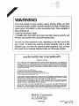
WARNING
Some dust created by power sanding, sawing, grinding, drilling, and other
construction activities contains chemicals known [to the State of Califomia] to
cause cancer, birth defects
or
other reproductive harm. Some examples
of
these chemicals are:
0
Lead from lead-based paints,
0
Crystalline silica from bricks and cement and other masonry products, and
Arsenic and chromium from chemically-treated lumber.
Your risk from these exposures varies, depending on how often you do this
type
of
work.
To
reduce your exposure to these chemicals:
work
in a well
ventilated area, and work with approved safety equipment, such as those
dust masks that are specially designed to filter out microscopic particles.
MAKITA
LIMITED
ONE
YEAR
WARRANTY
Warranty
Policy
original purcliase. Should any trouble develop during this one.ycar period return the COMPLETE
tool,
ireiglit
prepaid,
to
one
of
Makita’s Factory
or
Authorized Service Ceniers.
If
inspection
shows
the trouble is caused by defeftivc workmanship
01
material, Makita
will
rcplir
(or
at
our Option.
replace) without charge.
This Warranty
does
not apply where:
repairs have
been
made
or
lllcnIDled
by
others:
repairs
are
required
kcaux
of
normal wear and
tear:
The
tool
has
been
abusedd,
misused
or
impioperly maintained;
alterations have been made
lo
the tool.
IN NO EVENT SllALL MAKITA BE LIABLE FOR ANY INDIRECT. INClDENTAL
OR
CON-
SEQUEKTIAL DAMAGES FROM TllE SALE
OR
USE OFTHE PRODUCT. THIS DISCLAIMER
APPLIES BOT11
DlJRlNC
AND AFTER THETERM
OF
THIS WARRANTY.
MAKITA DISCLAIMS LIABILITY FOR ANY IMPLIED WARRANTIES. INCLUDING IMPLIED
WARRANTIES OF “MERCHANTABILITY” AND ”FITNESS
FOR
A SPECIFIC PURPOSE.”
AkTER TllE ONLYEAR TERM
OF
THIS
WARRANTY.
This Warranty
gives
you
specific
lcpl
rights, and you may
also
have other rights which vary
from
state
to
state. Some
states
do not allow the exclusion
or
limitation olincidcntal
or
consequential
damages.
so
the
above
Iunitation
or
exclusicn may
not
apply
to
you.
Some
slates
do not allow
liniitnlion on
how
long an implied warrmty
luls.
so
the above limitation may not apply
to
you.
Makita Corporation
3-11
-8,
Sumiyoshi-cho,
Anjo,
Aichi
446
Japan
883878A066
PRINTED
IN
JAPAN
1994-3-N
-
 1
1
-
 2
2
-
 3
3
-
 4
4
-
 5
5
-
 6
6
-
 7
7
-
 8
8
-
 9
9
-
 10
10
-
 11
11
-
 12
12


Makita 6920NB User manual
- Category
- Power tools
- Type
- User manual
Ask a question and I''ll find the answer in the document
Finding information in a document is now easier with AI
