
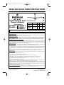
SPECIFICATIONS
Model No. Power Amps Watts RPM
HF948BS 1
HF948W 1
120V/60Hz 0.62 72 300
HF956BK 1
HF956BS 1 120V/60Hz 0.82 98 280
HF956W 1
LIMITED WARRANTY
What The Warranty Covers:
This warranty covers the motor and the other components and accessories of your Emerson ceiling fan against all defects in workmanship and
materials. You must be the original purchaser or user of the product to be covered.
What The Period Of Coverage Is:
As it applies to the motor, this warranty will last for two years from the date you purchased your ceiling fan. All other components and accessories
are covered by this warranty for one year from the date you purchased your ceiling fan. ANY IMPLIED WARRANTY OF MERCHANTABILITY OR
FITNESS FOR A PARTICULAR PURPOSE, MADE WITH RESPECT TO COMPONENTS AND ACCESSORIES IS ALSO LIMITED TO ONE YEAR.
What W
ill Emerson Electric Co. Do To Correct Problems:
Emerson Electric Co. will replace a defective Emerson Air Comfort Ceiling Fan motor, blade, component or other accessory at no charge to you. If
repair of the motor or blades is not practical or possible within a reasonable time and no replacement can be provided, Emerson Electric Co. will
refund the actual purchase price of your fan. We will ship the repaired product or replacement to you at no charge, but you are responsible for all
costs or removal, reinstallation and shipping of the product to Emerson Electric Co.
How Can Y
ou Get Service:
YOU MUST HAVE PROOF OF YOUR PURCHASE OF THE CEILING FAN TO OBTAIN LIMITED WARRANTY SERVICE. KEEP YOUR RECEIPT OR
OTHER PROOF OF PURCHASE. You can return the product to our factory or to your nearest authorized service center.
• To return the product to the factory, obtain a return authorization and service identification tag by writing to Air Comfort Products, Division
of Emerson Electric Co., 8100 W. Florissant Ave., St. Louis, MO 63136. Include all model numbers shown on the product with your request.
• To return the product to an authorized service center, call 1-800-654-3545 for the address of the nearest authorized service center.
You will be responsible for all insurance, freight or other transportation charges to our factory or authorized service center. Your Emerson Air
Comfort Ceiling Fan should be properly packed to avoid damage in transit since we will not be responsible for any such damage.
What Is Not Cover
ed:
The glass globes and light bulbs of your ceiling fan are not covered by this warranty. This warranty also does not cover any defects, malfunctions
or failures caused by:
• Repairs by persons not authorized by Emerson Electric Co.,
• Use of parts or accessories not authorized by Emerson Electric Co.,
• Mishandling, improper installation, modifications or damage to your ceiling fan while in your possession, or
• Unreasonable use, misuse, abuse, including failing to do reasonable and necessary maintenance, and normal wear and tear.
Additionally, this warranty and any implied warranty of merchantability or fitness for a particular purpose are voided when:
• The original purchaser or user ceases to own the product, or
• The fan is moved from its original point of installation.
This warranty is only valid within the 50 states of the United States and the District of Columbia. No other written or oral warranties apply, and
no employee, agent, dealer or other person is authorized to give any warranties on behalf of Emerson Electric Co.
REPAIR, REPLACEMENT OR A REFUND ARE THE EXCLUSIVE REMEDIES AVAILABLE UNDER THIS WARRANTY AND EMERSON IS NOT
RESPONSIBLE FOR DAMAGES OF ANY KIND, INCLUDING INCIDENTAL AND CONSEQUENTIAL DAMAGES. Incidental damages include but are
not limited to such damages as loss of time and loss of use. Consequential damages include but are not limited to the cost of repairing or
replacing other property which was damaged if this product does not work properly.
How State Law Relates T
o The Warranty:
Some states do not allow the exclusion or limitation of incidental or consequential damages so the above exclusion or limitation may not apply
to you. This warranty gives you specific legal rights, and you may also have other rights which vary from state to state.
Part No. F40BP73110001 Form No. BP7311-1
U.L. Model No.: HF948, HF956
READ AND SAVE THESE INSTRUCTIONS
48” & 56”
Industrial Heat Fans
Owner's Manual
10' MIN.
TO FLOOR
HF956 Net Weight: 22.2 Lbs.
HF948 Net Weight: 18.7 Lbs.
Model Numbers
HF948BS 1 HF956BK 1
HF948W 1 HF956BS 1
HF956W 1
BP7311 48 56" Heat Fans 1/16/08 10:52 AM Page 1

2
To avoid fire, shock, and serious personal injury, follow these
instructions.
Safety Instructions
1. Read your owner’s manual carefully and keep it for future reference.
2. Before servicing or cleaning unit, switch power off at service panel and lock service
panel disconnecting means to prevent power from being switched on accidentally.
When the service disconnecting means cannot be locked, securely fasten a
warning device, such as a tag, to the service panel.
3. Be careful of the fan and blades when cleaning, painting, or working near the fan.
Always turn off the power to the ceiling fan before servicing.
4. Suitable for use with solid-state speed controls.
5. Do not bend the blade flanges when installing the blades, balancing the blades, or
cleaning the fan. Do not insert foreign objects in between the rotating blades.
Additional Safety Instructions for Installation
1. To avoid possible shock, be sure electricity is turned off at the fuse box before
wiring, and do not operate fan without blades.
2. All wiring must satisfy National and Local Electrical Codes. Use the National
Electrical Code if Local Codes do not exist. The ceiling fan must be grounded as a
precaution against possible electrical shock. Electrical installation should be made
or approved by a licensed electrician.
3. The outlet box and joist must be securely mounted and capable of reliably
supporting at least 50 pounds. Use only U.L. outlet boxes listed as “Acceptable for
Fan Support of 50 lbs or less”, and use the mounting screws provided with the
outlet box. Most outlet boxes commonly used for support of light fixtures are not
acceptable for fan support and may need to be replaced. Consult a qualified
electrician if in doubt.
4. The fan must be mounted with the fan blades at least 10 feet from the floor to
prevent accidental contact with the fan blades.
5. Suitable for use with solid-state speed controls.
6. Always properly connect the retention cable included with this fan (follow the
“Installation Instructions” section carefully).
7. The support beam or joist must be secure and capable of supporting at least 50
pounds.
8. Follow the recommended instructions for the proper method of wiring your ceiling
fan. If you do not know enough about electrical wiring, have your fan installed by a
licensed electrician.
WARNING: To avoid fire, shock or injury, do not use an Emerson or any other brand
of control not specifically approved for this fan.
WARNING: This product is designed to use only those parts supplied with this
product and/or any accessories designated specifically for use with this product by
Emerson Electric Co. Substitution of parts or accessories not designated for use with
this product by Emerson Electric Co. could result in personal injury or property
damage.
WARNING: To reduce the risk of personal injury, do not bend the blade flange when
installing the blade flanges, balancing the blades or cleaning the fan. Do not insert
foreign objects in between rotating fan blades.
WARNING:To reduce the risk of electric shock, this fan must be installed with an
isolating wall control/switch.
WARNING
DATE CODE:
The date code of this fan may be found on the box, stamped in ink on a white label.
You should record this data above and keep it in a safe place for future use.
U.L. Model No.: HF948, HF956
BP7311 48 56" Heat Fans 1/16/08 10:52 AM Page 2

3
Do not install or use fan if any part is
damaged or missing. Call Toll-Free:
1-800-654-3545
WARNING
This product is designed to use only
those parts supplied with this product
and/or any accessories designated
specifically for use with this product by
Emerson Electric Co. Substitution of
parts or accessories not designated for
use with this product by Emerson Electric
Co. could result in personal injury or
property damage.
WARNING
Checking Contents of
Package
Electrical Requirements
1. Unpack the items carefully to avoid
damage to any of the components.
2. Make certain you receive the following
parts:
a. Motor subassembly
b. Blades (3 each)
c. Upper canopy
d. Lower canopy
e. J-hook bag assembly containing:
1. J-hook (2 each)
2. Flat washers (2 each)
3. Lock washers (2 each)
4. Hex nuts (2 each)
f. 24" Hanger pipe assembly
g. 8” Hanger pipe(HF948 Only)
h. Bag of parts containing:
1. Wire connectors (3 each)
2. Cable clamps (2 each)
3. M6 x 1/2" Hex head screws
(6 each)
4. M6 Spring washers (6 each)
5. Blade gaskets (3 each)
6. Clevis pin
7. Hairpin clip
8. 5/16-18 x 1/4” Setscrews (2 each)
9. Allen wrench
NOTE: Intermixing blades between
fans can cause excessive wobble.
Keep blades in original sets of three.
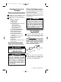
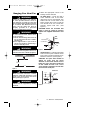
Fan Assembly
Instructions
1. Put the upper canopy and lower
canopy on the hanger pipe assembly,
facing in the proper direction. (See
Figure 1.)
NOTE: For HF948 Only
. If you are going
to use the 8” pipe, first remove the
hanger assembly from the 22” pipe and
install it on the 8” pipe. Be sure that the
nut is securely tightened and the
hairpin clip properly installed.
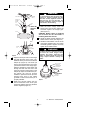
2. Pass the motor wires and retention
cable through the hanger pipe
assembly and seat the hanger pipe in
the motor yoke. (See Figure 2.)
HANGER PIPE
ASSEMBLY
LOWER
CANOPY
UPPER
CANOPY
HANGER
ASSEMBLY
Figure 1
Before discarding packaging material,
be certain all parts have been removed.
Your new ceiling fan will require a
grounded electrical supply line of 120 volts
AC, 60 Hz, 15 amp circuit.
The outlet box must be securely anchored
and capable of withstanding a load of at
least 50 pounds.
Turning off wall switch is not sufficient.
To avoid possible electrical shock, be
sure electricity is turned off at the main
fuse box before wiring. All wiring must be
in accordance with National and Local
codes and the ceiling fan must be
properly grounded as a precaution
against possible electrical shock.
WARNING
U.L. Model No.: HF948, HF956
BP7311 48 56" Heat Fans 1/16/08 10:52 AM Page 3

RUBBER
GROMMET
CLEVIS
PIN
HAIRPIN
CLIP
MOTOR
YOKE
HANGER PIPE
ASSEMBLY
MOTOR WIRE (3)
RETENTION
CABLE (1)
MOTOR
HAIRPIN
CLIP
CLEVIS
PIN
5/16-18
SETSCREW (2)
Figure 2
CANOPIES NOT
SHOWN FOR
CLARITY
4
5. Slide the lower canopy down the
hanger pipe and securely tighten the
set-screw against the hanger pipe.
(See Figure 3.)
CAUTION: Blades come in balanced
sets of three. Do not mix blades if
installing more than one fan.
6. Install the blade gaskets between the
blades and the motor. (See Figure 3.)
7. Install the three blades onto the motor
using spring washers, M6 x 1/2" screws
and blade gaskets supplied. Securely
tighten the six blade screws.
It is critical that the clevis pin in the motor
coupling is properly installed and the
setscrews securely tightened. Failure to
verify that the pin and setscrews are
properly installed (as shown in Figure 3)
could result in the fan falling.
WARNING
To reduce the risk of personal injury, do
not bend the blade flanges when
installing the blades, balancing the
blades, or cleaning the fan. Do not insert
foreign objects between rotating fan
blades.
WARNING
BLADE
BLADE GASKET
SPRING WASHER
(2 PER BLADE)
M6 x 1/2" SCREW
(2 PER BLADE)
Figure 3
3. Align the clevis pin holes in the hanger
pipe with the holes in the motor yoke.
Install the clevis pin and secure with the
hairpin clip (Figure 2). The clevis pin
must go through the holes in the motor
yoke and the holes in the hanger pipe.
Push the straight leg of the hairpin clip
through the hole near the end of the
clevis pin until the curved portion of the
hairpin clip snaps around the clevis pin.
The hairpin clip must be properly
installed to prevent the clevis pin from
working loose. Pull on the rubber
grommet to make sure the clevis pin is
properly installed.
4. Install and securely tighten the two
5/16-18 setscrews in the motor yoke
against the hanger pipe using the allen
wrench supplied. (Figure 2.)
U.L. Model No.: HF948, HF956
BP7311 48 56" Heat Fans 1/16/08 10:52 AM Page 4

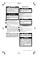
1. Attach the appropriate J-hook to the
building structure member.
On Steel Beam - Locate and drill a
13/32” diameter hole in the beam.
(See Figure 5.) Use a flat washer, lock
washer and nut on both sides of the
beam. Position the J-hook so that the
hook extends 2-1/2” out of outlet box.
Securely tighten both nuts. (See
Figure 5.)
CAUTION: When the threaded bolt
hook is used, be careful to securely
tighten with supplied lockwashers and
nuts.
On Wood Joist - Locate and drill a pilot
hole in the wood joist. Install the screw
type J-hook so that hook extends 2-1/2”
below the outlet box. (See Figure 6.)
CAUTION: The pilot hole should be
drilled no larger than the minor
diameter of the screw threads on the
hook (1/4” max.). Do not put a lubricant
on the J-hook. At least 1-1/2” of the
screw threads should be secured into
the structural wood joist.
Hanging Your Heat Fan
5
Turning off wall switch is not sufficient.
To avoid possible electrical shock, be
sure electricity is turned off at the main
fuse box before wiring. All wiring must be
in accordance with National and Local
codes and the ceiling fan must be
properly grounded as a precaution
against possible electrical shock.
WARNING
To reduce the risk of fire, electric shock,
or personal injury:
a. The fan must be hung with at least 10
foot of clearance from floor to blades.
(See Figure 4).
b. Your support beam or joist must be
secure and capable of withstanding a
load of at least 50 pounds.
WARNING
The fan must be hung with at least 10' of
clearance from floor to blades (Figure 4).
WARNING
CEILING
FLOOR
10 FOOT
MINIMUM
Figure 4
NUT
LOCK WASHER
FLAT WASHER
OUTLET
BOX
2-1/2"
Figure 5
2-1/2"
1-1/2"
OUTLET
BOX
Figure 6
STEEL
BEAM
WOOD JOIST
Read and follow instructions carefully.
Failure to comply with instructions could
result in risk of fire, electric shock, fan
falling and injury to persons.
WARNING
J-Hook must be supported by building
structure.
WARNING
U.L. Model No.: HF948, HF956
BP7311 48 56" Heat Fans 1/16/08 10:52 AM Page 5

6
Wiring Your Heat Fan
NOTE: If you feel that you do not have
enough electrical wiring knowledge or
experience, have your fan installed by a
licensed electrician.
1. Connect the green grounding wire from
the fan motor to the green grounding
wire from the supply source. Securely
connect wires with wire connectors
supplied. (See Figure 9.)
CAUTION: Use larger U.L. listed wire
connectors if supply source wires are
larger than #12 AWG.
2. Securely connect the fan motor white
wire to the supply white (neutral) wire
using a wire connector supplied (Figure
9). Securely connect the fan motor
black wire to the supply black (hot) wire
using wire connector supplied. After
connections have been made, turn
leads upward and carefully push leads
into the outlet box, with the white and
green leads on one side of the outlet
box and the black leads on the other
side of the outlet box.
To avoid possible fire or electrical shock,
do not pinch wires between the hanger
ball/downrod assembly and hanger
bracket.
WARNING
To avoid possible electrical shock, be
sure electricity is turned off at the main
fuse box before wiring.
NOTE: If you are not sure if the outlet box
is grounded, contact a licensed
electrician for advice, as it must be
grounded for safe operation.
WARNING
GROUND WIRE
BLACK SUPPLY
(HOT)
BLACK FAN WIRE
GREEN WIRE (GROUND)
FROM FAN
WIRE CONNECTORS (3)
WHITE SUPPLY
(NEUTRAL)
WHITE FAN WIRE
Figure 9
2. Lift the fan onto the J-hook and position
as shown in Figure 7. Make sure the
motor wires and retention cable at the
top of the hanger pipe are positioned
behind J-hook as illustrated in Figure 7.
CAUTION: The electrical wires and
retention cable must not be placed
between the rubber roller and the hook,
but rather as illustrated in Figure 7.
3. This fan is equipped with the required
retention cable. This cable must be
affixed to the building structure and
securely clamped in such a manner to
support the weight of the fan in the
event the mounting hook or other parts
fail. After wrapping cable around or to a
structural member that will support 50
pounds, secure cable with supplied
cable clamps as illustrated in Figure 8.
NOTE: Leave approximately 3" but no
more than 5" of slack on this safety
cable to allow for possible fan
movement. Do not exceed more than 5"
total slack.
CAUTION: It is important to note the
proper installation position of the cable
clamps as illustrated in Figure 8. To
obtain maximum holding power, install
U-bolt section of clip on dead or short
end of cable and saddle on long end of
cable. Improper installation reduces
the efficiency of the connection by as
much as 40 percent.
CABLE
CLAMPS
RETENTION
CABLE
Figure 7
TO SUPPORT
STRUCTURE
TO
FAN
CABLE
CLAMPS
Figure 8
U.L. Model No.: HF948, HF956
BP7311 48 56" Heat Fans 1/16/08 10:52 AM Page 6

Maintenance
LUBRICATION - All bearings are
permanently lubricated and do not require
further lubrication.
CLEANING - This fan may be wiped off
with a damp cloth. Do not allow the motor
to get wet. Do not use solvents or harsh
detergents.
7
Check to see that all connections are
tight, including ground, and that no bare
wire is visible at the wire connectors,
except for the ground wire.
CAUTION:Do not operate fan until blades
are in place. Noise and fan damage could
result.
WARNING
To avoid possible fire or shock, make
sure that the electrical wires are
completely inside the outlet box and not
pinched between the ceiling cover and
the ceiling.
WARNING
3. Slide the upper canopy up the rod
within 1/4" of the ceiling or beam and
securely tighten the setscrew.
4. If a remote speed control is to be used
refer to the instructions included with
that control for proper installation and
wiring.
5. Restore power.
6. After completing installation, test run
fan in normal operation manner.
Inspect for any possible shake or
wobble which may be caused by
binding as a result of "tight cable". if this
should happen, shut off power supply
and re-check instructions to correct
problem.
NOTE: When any solid state motor
speed control is used, a humming
noise may be present in the fan on low
speed. This hum in no way affects the
operation of the fan and is acceptable
in most industrial installations.
To avoid possible electrical shock, be
sure electricity is turned off at the main
service box before servicing.
WARNING
Do not use water when cleaning your
ceiling fan. It could damage the motor or
the blades and create the possibility of an
electrical shock.
WARNING
The use of any other control not
specifically approved for this fan could
result in fire, shock and personal injury.
WARNING
This product is designed to use only
those parts supplied with this product
and/or any accessories designated
specifically for use with this product by
Emerson Electric Co. Substitution of
parts or accessories not designated for
use with this product by Emerson Electric
Co. could result in personal injury or
property damage.
WARNING
Accessories
1. Downrod Extension Kits (see store or
catalog).
2. Ceiling Fan/Light Controls (see store or
catalog).
3. Suitable for use with Emerson Solid-
State Speed Control.
U.L. Model No.: HF948, HF956
BP7311 48 56" Heat Fans 1/16/08 10:52 AM Page 7

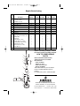
Part Numbers
Key Model No. Model No. Model No. Model No. Model No.
No. Description HF948BS 1 HF948W 1 HF956BK 1 HF956BS 1 HF956W 1
1 J-Hook Bag Assembly: 761385 761385 761385 761385 761385
J-Hooks (2 each) — — — — —
Hardware (2 each) — — — — —
2 Hanger Assembly 761339 761339 761339 761339 761339
3 Pipe Nipple (8”) 761387-5 761387-2 — —
4 Pipe Nipple (22”) 761387-6 761387 761387-4 761387-7 761387
5 Upper Canopy 761335-BS 761335 761335-2 761335-BS 761335
6 Lower Canopy 761336-BS 761336 761336-2 761336-BS 761336
7 Blades (Set of 3) 763095-BS 763095 763094-1 763094-BS 763094
8 Capacitor — — — — —
* Parts Bag, Containing: 761384 761384 761384 761384 761384
9 5/16-18 x 1/4” Setscrews (2 ea.) — — — — —
10 Hairpin Clip — — — — —
11 Clevis Pin — — — — —
12 Cable Clamp (2 each) — — — — —
13 Screw, M6 x 1/2” (6 each) — — — — —
14 Spring Washer, M6 (6 each) — — — — —
15 Blade Gasket (3 each) — — — — —
16 Wire Connector (3 each) — — — — —
17 Allen Wrench — — — — —
— Owner's Manual BP7311-1 BP7311-1 BP7311-1 BP7311-1 BP7311-1
Repair Parts Listing
1
2
4
5
6
10
11
17
13
12
16
14
7
15
8
9
3
Before discarding packaging material,
be certain all parts have been removed.
HOW TO ORDER REPAIR
PARTS
WHEN ORDERING REPAIR PARTS,
ALWAYS GIVE THE FOLLOWING
INFORMATION:
• PART NUMBER
• NAME OF ITEM
• PART DESCRIPTION
• MODEL NUMBER
The model number of your Fan will be
found on a label attached to the top
housing.
For repair parts, phone 1-800-654-3545.
Part No. F40BP73110001 Printed in China 01/08
Form No. BP7311-1
Air Comfort Products
DIVISION OF EMERSON ELECTRIC CO.
8100 W. Florissant • St. Louis, MO 63136
U.L. Model No.: HF948, HF956
BP7311 48 56" Heat Fans 1/16/08 10:52 AM Page 8
-
 1
1
-
 2
2
-
 3
3
-
 4
4
-
 5
5
-
 6
6
-
 7
7
-
 8
8


Emerson HF948W User manual
- Category
- Household fans
- Type
- User manual
Ask a question and I''ll find the answer in the document
Finding information in a document is now easier with AI
Related papers
-
Emerson CF755AGW05 User manual
-
-
-
-
-
-
-
-
-
Other documents
-
Delta RS1000W User manual
-
Illumine CLI-EMM006067 Installation guide
-
Hunter Fan CF652WW01 User manual
-
-
-
-
-
Electrolux CF921BS00 User manual
-
-