Harbor Freight Tools 94280 User manual
- Category
- Power tools
- Type
- User manual

MULTI-PURPOSE FLOOR MACHINE
Model 94280
ASSEMBLY AND OPERATING INSTRUCTIONS
3491 Mission Oaks Blvd., Camarillo, CA 93011
Visit our Web site at: http://www.harborfreight.com
Copyright © 2006 by Harbor Freight Tools
®
. All rights reserved. No portion of this
manual or any artwork contained herein may be reproduced in any shape or form
without the express written consent of Harbor Freight Tools.
For technical questions, please call 1-800-444-3353.
®
TO PREVENT SERIOUS INJURY,
READ AND UNDERSTAND ALL WARNINGS
AND INSTRUCTIONS BEFORE USE.
Due to continuing improvements, actual product may differ slightly from the product described herein.

Page 2SKU 94280
For technical questions, please call 1-800-444-3353.
PRODUCT SPECIFICATIONS
Electrical Requirements 115 V~ / 60 Hz / 250 W
Motor Single Speed / 0.3 HP / 150 RPM
Power Plug/Cord 3-Prong with Ground
18 AWG x 3 C SJTX x 19 Ft.
Dimensions 10” Outside Diameter Base (11” O.D. w/Brush Attached)
8-1/2” Wide at Wheels (9” Wide at Axle)
35” Long Tube Handle w/Yoke
12-1/2” Wide “T” Handle
48-3/4” High (From Floor to Handle)
Accessories 11” Diameter Carpet Brush (Black w/Slip Fit)
11” Diameter Floor Brush (Green/White w/Slip Fit)
12” Diameter Foam Pad (White w/Hook & Loop)
Weight 41 Pounds
SAVE THIS MANUAL
You will need this manual for the safety warnings and precautions, assembly, oper-
ating, inspection, maintenance and cleaning procedures, parts list and assembly diagram.
Keep your invoice with this manual. Write the invoice number on the inside of the front
cover. Keep this manual and invoice in a safe and dry place for future reference.
GENERAL SAFETY RULES
WARNING!
READ AND UNDERSTAND ALL INSTRUCTIONS
Failure to follow all instructions listed below may result in
electric shock, fire, and/or serious injury.
SAVE THESE INSTRUCTIONS
WORK AREA
Keep your work area clean and well lit. Cluttered benches and dark areas invite
accidents.
Do not operate power tools in explosive atmospheres, such as in the pres-
ence of flammable liquids, gases, or dust. Power tools create sparks which may
ignite the dust or fumes.
Keep bystanders, children, and visitors away while operating a power tool.
Distractions can cause you to lose control. Provide barriers or shields as needed.
1.
2.
3.

Page 3SKU 94280
For technical questions, please call 1-800-444-3353.
ELECTRICAL SAFETY
Grounded tools must be plugged into an outlet properly installed and grounded
in accordance with all codes and ordinances. Never remove the grounding
prong or modify the plug in any way. Do not use any adapter plugs. Check with
a qualified electrician if you are in doubt as to whether the outlet is properly
grounded. If the tools should electrically malfunction or break down, grounding
provides a low resistance path to carry electricity away from the user.
Double insulated tools are equipped with a polarized plug (one blade is wider
than the other). This plug will fit in a polarized outlet only one way. If the plug
does not fit fully in the outlet, reverse the plug. If it still does not fit, contact
a qualified electrician to install a polarized outlet. Do not change the plug
in any way. Double insulation eliminates the need for the three wire grounded
power cord and grounded power supply system.
Avoid body contact with grounded surfaces such as pipes, radiators, ranges,
and refrigerators. There is an increased risk of electric shock if your body is
grounded.
Do not expose power tools to rain or wet conditions. Water entering a power
tool will increase the risk of electric shock.
Do not abuse the Power Cord. Never use the Power Cord to carry the tools or
pull the Plug from an outlet. Keep the Power Cord away from heat, oil, sharp
edges, or moving parts. Replace damaged Power Cords immediately. Dam-
aged Power Cords increase the risk of electric shock.
When operating a power tool outside, use an outdoor extension cord marked
“W-A” or “W”. These extension cords are rated for outdoor use, and reduce the
risk of electric shock.
PERSONAL SAFETY
Stay alert. Watch what you are doing, and use common sense when operating
this product. Do not use the Floor Machine while tired or under the influence
of drugs, alcohol, or medication. A moment of inattention while operating this
product may result in serious personal injury.
Dress properly. Do not wear loose clothing or jewelry. Contain long hair.
Keep your hair, clothing, and gloves away from moving parts. Loose clothes,
jewelry, or long hair can be caught in moving parts.
Avoid accidental starting. Make sure the Power Cord remains unplugged from its
electrical outlet until this product is completely assembled and ready to use.
Do not overreach. Keep proper footing and balance at all times. Proper footing
and balance enables better control of this product in unexpected situations.
1.
2.
3.
4.
5.
6.
1.
2.
3.
4.

Page 4SKU 94280
For technical questions, please call 1-800-444-3353.
Use safety equipment. Wear eye protection when assembling this product.
Non-skid safety shoes must be used for appropriate conditions.
TOOL USE AND CARE
Disconnect the Power Cord Plug from the power source before making any
adjustments, changing accessories, or storing the Floor Machine. Such pre-
ventive safety measures reduce the risk of starting the unit accidentally.
Store idle equipment out of reach of children and other untrained persons.
Electrically powered products are dangerous in the hands of untrained users.
Check for misalignment or binding of moving parts, breakage of parts, and
any other condition that may affect this product’s operation. If damaged, have
the Floor Machine serviced before using. Many accidents are caused by poorly
maintained equipment.
SERVICE
Service must be performed only by qualified repair personnel. Service or
maintenance performed by unqualified personnel could result in a risk of injury.
When servicing this product, use only identical replacement parts. Follow
instructions in the “Inspection, Maintenance, And Cleaning” section of this
manual. Use of unauthorized parts or failure to follow maintenance instructions
may create a risk of electric shock or injury.
SPECIFIC SAFETY RULES
Maintain labels and nameplates on the Floor Machine. These carry important
information. If unreadable or missing, contact Harbor Freight Tools for a replace-
ment.
Wear ANSI-approved safety impact eye goggles and non-slip foot-
wear when using the Floor Machine. Using personal safety devices
reduce the risk for injury.
Maintain a safe environment. Keep the area well lit. Make sure there is adequate
surrounding space. Always keep the area free of obstructions, grease, oil, trash,
and other debris. Do not use an electrically powered product in areas near flam-
mable chemicals, dusts, and vapors.
Never leave the Floor Machine unattended when it is plugged into an electrical
outlet. Turn off the Floor Machine and unplug the tool before leaving.
Carefully inspect the condition of the Floor Machine before use, and check
the tool continually during use. If any damage is noted, stop immediately and
repair or replace the Floor Machine.
5.
1.
2.
3.
1.
2.
1.
2.
3.
4.
5.

Page 5SKU 94280
For technical questions, please call 1-800-444-3353.
Avoid electrical shock. Make sure the Floor Machine is unplugged
from its electrical outlet prior to performing any inspection, maintenance,
or cleaning procedures. Do not use the Floor Machine in the rain or in
wet conditions. Plug the Power Cord of this unit only into a 3-hole, 115
volt, Ground Fault Circuit Interrupter (GFCI), electrical outlet for addi-
tional protection from electric shock.
Use the right product for the job. There are certain applications for which this
product was designed. Do not use small tools, equipment, or accessories to do the
work of larger industrial tools, equipment, or accessories. Do not use this product
for a purpose for which it was not intended.
Do not allow children or other unauthorized people to handle or play with
this product.
Industrial applications must follow OSHA requirements.
To reduce the risk of fire, use only commercially available floor cleaners and
waxes.
WARNING! People with pacemakers should consult their physician(s) before
using this product. Electromagnetic fields in close proximity to a heart pacemaker
could cause interference to or failure of the pacemaker. In addition, people with
pacemakers should adhere to the following: Avoid operating power tools alone.
Don’t use a power tool with the Power Switch locked on. If powered via a Power
Cord be certain that the tool is properly grounded. A ground fault interrupt (GFCI)
system is also a good precaution. This inexpensive device is a good safety measure
because it prevents a sustained electrical shock. Properly maintain and inspect all
tools before use to avoid electrical shock.
WARNING! The warnings and cautions discussed in this manual cannot cover
all possible conditions and situations that may occur. It must be understood by the
operator that common sense and caution are factors which cannot be built into this
product, but must be supplied by the operator.
SAVE THESE INSTRUCTIONS
6.
7.
8.
9.
10.
11.
12.

Page 6SKU 94280
For technical questions, please call 1-800-444-3353.
GROUNDING
WARNING!
Improperly connecting the grounding wire can result in the risk of electric shock.
Check with a qualified electrician if you are in doubt as to whether the outlet is
properly grounded. Do not modify the power cord plug provided with the tool.
Never remove the grounding prong from the plug. Do not use the tool if the
power cord or plug is damaged. If damaged, have it repaired by a service facil-
ity before use. If the plug will not fit the outlet, have a proper outlet installed by
a qualified electrician.
GROUNDED TOOLS: TOOLS WITH THREE PRONG PLUGS
Tools marked with “Grounding Required” have a three wire cord and three prong
grounding plug. The plug must be connected to a properly grounded outlet. If the
tool should electrically malfunction or break down, grounding provides a low resis-
tance path to carry electricity away from the user, reducing the risk of electric shock.
(See 3-Prong Plug and Outlet.)
The grounding prong in the plug is connected through the green wire inside the
cord to the grounding system in the tool. The green wire in the cord must be the
only wire connected to the tool’s grounding system and must never be attached to
an electrically “live” terminal. (See 3-Prong Plug and Outlet.)
Your tool must be plugged into an appropriate outlet, properly installed and grounded
in accordance with all codes and ordinances. The plug and outlet should look like
those in the following illustration. (See 3-Prong Plug and Outlet.)
THIS PRODUCT
USES A
3-PRONG
ELECTRICAL
PLUG
3-Prong Plug and Outlet Outlets for 2-Prong Plug
DOUBLE INSULATED TOOLS: TOOLS WITH TWO PRONG PLUGS
Tools marked “Double Insulated” do not require grounding. They have a special
double insulation system which satisfies OSHA requirements and complies with
the applicable standards of Underwriters Laboratories, Inc., the Canadian Standard
Association, and the National Electrical Code. (See Outlets for 2-Prong Plug.)
1.
2.
3.
1.

Page 7SKU 94280
For technical questions, please call 1-800-444-3353.
Double insulated tools may be used in either of the 120 volt outlets shown in the
preceding illustration. (See Outlets for 2-Prong Plug.)
EXTENSION CORDS
Grounded tools require a three wire extension cord. Double Insulated tools can
use either a two or three wire extension cord.
As the distance from the supply outlet increases, you must use a heavier gauge
extension cord. Using extension cords with inadequately sized wire causes a seri-
ous drop in voltage, resulting in loss of power and possible tool damage.
(See Table A.)
The smaller the gauge number of the wire, the greater the capacity of the cord. For
example, a 14 gauge cord can carry a higher current than a 16 gauge cord.
(See Table A.)
When using more than one extension cord to make up the total length, make sure
each cord contains at least the minimum wire size required. (See Table A.)
If you are using one extension cord for more than one tool, add the nameplate am-
peres and use the sum to determine the required minimum cord size.
(See Table A.)
If you are using an extension cord outdoors, make sure it is marked with the suffix
“W-A” (“W” in Canada) to indicate it is acceptable for outdoor use.
Make sure your extension cord is properly wired and in good electrical condition.
Always replace a damaged extension cord or have it repaired by a qualified electri-
cian before using it.
Protect your extension cords from sharp objects, excessive heat, and damp or wet
areas.
2.
1.
2.
3.
4.
5.
6.
7.
8.

Page 8SKU 94280
For technical questions, please call 1-800-444-3353.
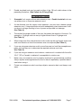
RECOMMENDED MINIMUM WIRE GAUGE FOR EXTENSION CORDS*
(120 OR 240 VOLT)
NAMEPLATE
AMPERES
(at full load)
EXTENSION CORD LENGTH
25 Feet 50 Feet 75 Feet 100 Feet 150 Feet
0 – 2.0 18 18 18 18 16
2.1 – 3.4 18 18 18 16 14
3.5 – 5.0 18 18 16 14 12
5.1 – 7.0 18 16 14 12 12
7.1 – 12.0 18 14 12 10 -
12.1 – 16.0 14 12 10 - -
16.1 – 20.0 12 10 - - -
TABLE A
* Based on limiting the line voltage drop to five volts at 150% of the rated amperes.
SYMBOLOGY
Double Insulated
Canadian Standards Association
Underwriters Laboratories, Inc.
V~
Volts Alternating Current
A
Amperes
n
0
xxxx/min.
No Load Revolutions per Minute (RPM)
UNPACKING
When unpacking, check to make sure all the parts shown on the Parts List at the
end of the manual are included. If any parts are missing or broken, please call Harbor
Freight Tools at the number shown on the cover of this manual as soon as possible.

Page 9SKU 94280
For technical questions, please call 1-800-444-3353.
ASSEMBLY
Note: For additional information regarding the parts listed in the following pages, refer to
the Assembly Diagram at the end of the manual.
CAUTION! Always make sure the Floor Machine is disconnected from its electrical
outlet prior to assembling the tool, changing accessories, or performing service to
the product.
Wear ANSI-approved safety impact eye goggles and non-slip foot-
wear when using the Floor Machine. Using personal safety devices
reduce the risk for injury.
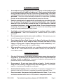
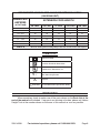
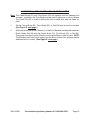
Install the Handle Tube And Locking Pin
Turn the Chassis (1) upside-down and gently press the tab on the Screw Box (10)
from underneath using a screwdriver, see lower left. Remove the Screw Box.
Tab
Handle
Screw
(11)
storage
hole
transport
hole
Align the mounting holes in the lower portion of the Handle Tube (21) with the front
two mounting holes in the bracket at the rear of the Floor Machine’s Chassis (1).
This is the location that the Handle Screw is shown to the top left. Then secure the
Handle Tube to the Chassis, using one Handle Screw (11), two Flat Washers (12),
and one Hex Lock Nut (13). Replace the Screw Box (10).
For storage, raise the Handle Tube (21) to its highest point. Then, insert the Locking
Pin (16) through the storage hole shown above.
For transport, raise the Handle Tube (21) to its highest point. Then, insert the Lock-
ing Pin (16) through the transport hole shown above.
1.
2.
1.
2.
3.
4.
REV 07e

Page 10SKU 94280
For technical questions, please call 1-800-444-3353.
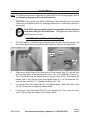
Install A Carpet Brush, Floor Brush, Or Foam Pad
Note: The Carpet Brush (51) and Floor Brush (52) are typically used for cleaning floor
surfaces. In addition, the Floor Brush may be used to apply wax to a floor surface.
The Foam Pad (54) is used for buffing the floor surface after wax has been ap-
plied.
Set the Carpet Brush (51), Floor Brush (52), or Pad (54) level on the floor surface.
(See Figure E, next page.)
With both hands pick up the Chassis (1) of the Floor Machine and align the machine’s
Brush Holder Pad (35) with the Carpet Brush (51), Floor Brush (52), or Pad (54).
Then push down firmly on the Chassis to secure the Brush or Pad in place. NOTE:
The Brushes and Foam Pad fit snugly onto the Brush Holder Pad, and may require
additional effort to install. (See Figure E, next page.)
1.
2.

Page 11SKU 94280
For technical questions, please call 1-800-444-3353.
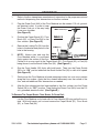
OPERATION
Refer to the floor cleaner/wax manufacturer’s instructions for the proper amount and
method of dispensing floor cleaner/wax on the floor surface.
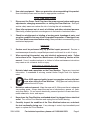
Plug the Power Cord (34A) of the Floor Machine into the nearest 115 volt, ground-
ed, electrical outlet. In order to keep
the Power Cord out of the way, hang
it over your shoulder.
(See Figure E.)
Position the Carpet Brush (51), Floor
Brush (52), or Foam Pad (54) on the
floor surface. (See Figure E.)
Remove the Locking Pin (16) from the
holes in the bracket and place it in the
hole in the housing.
NOTE: Always start and stop the
Floor Machine while it is positioned
firmly against the surface of the floor.
Failure to do so may result in the Carpet Brush (51), Floor Brush (52), or Pad (54)
being thrown from the Brush Holder Pad (35). (See Figure E.)
Grip the Front Handle (26) firmly with both hands. Then turn the Power Switch
(29) to its “ON” position and allow the Brush Holder Pad (35) to orbit at full speed.
(See Figure E.)
Slowly move the Floor Machine in broad sweeping strokes in a criss-cross pattern
along the floor surface. Apply the floor cleaner/wax evenly over the surface of the
floor, and add additional floor cleaner/wax as needed.
After the floor cleaner/wax has been applied to the floor surface, turn the Power
Switch (29) to its “OFF” position. Then unplug the Power Cord (34A) from the 115
volt, grounded, electrical outlet. (See Figure E.)
To Remove The Carpet Brush, Floor Brush, Or Foam Pad:
Lay the Floor Machine on its back with its Front Handle (26) lying on the floor sur-
face. With both hands, pull out and remove the Carpet Brush (51), Floor Brush
(52), or Foam Pad (54).
1.
2.
3.
4.
5.
6.
7.
8.
CARPET BRUSH (51)
FLOOR BRUSH (52)
PAD (54)
POWER
CORD
(34A)
FRONT HANDLE (26)
POWER SWITCH (29)
BRUSH
HOLDER
PAD (35)
CHASSIS (1)
FIGURE E
CARPET BRUSH (51)
FLOOR BRUSH (52)
PAD (54)
POWER
CORD
(34A)
FRONT HANDLE (26)
POWER SWITCH (29)
BRUSH
HOLDER
PAD (35)
CHASSIS (1)
FIGURE E

Page 12SKU 94280
For technical questions, please call 1-800-444-3353.
INSPECTION, MAINTENANCE, AND CLEANING
WARNING! Make sure the Floor Machine is disconnected from its electrical
outlet prior to performing any inspection, maintenance, or cleaning procedures.
Before each use, inspect the general condition of the Floor Machine. Check for
cracked or broken parts, damaged electrical wiring, and any other condition that
may affect safe operation. If abnormal noise or vibration occurs, have the problem
corrected before further use.
Do not use damaged equipment.
After each use, remove the Carpet Brush (51), Floor Brush (52), or Pad (54). This
will allow the Brushes and Pad to dry and retain their original shape. To prolong
the life and shape of the Brushes and Pad, store them face up.
To clean: Use a clean cloth and mild detergent to clean the exterior of the Floor
Machine. Do not immerse the Floor Machine in liquid.
When storing, make sure to store the Floor Machine in a clean, dry, safe location
out of reach of children and other unauthorized people.
CAUTION! All maintenance, service, or repairs not mentioned in this
manual must only be performed by a qualified service technician.
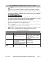
TROUBLESHOOTING
Problem Possible Cause Possible Solution
Machine will not run. Not firmly plugged into electrical
outlet.
Capacitor (47A) malfunction.
1.
2.
Make sure the power plug is plugged
into a working, 115 volt, grounded,
electrical outlet.
Have a qualified technician check
capacitor.
1.
2.
Machine bounces. Using carpet brush (51) on dry
surface without dry shampoo or
wet shampoo.
Carpet brush (51) or brush holder
pad (35) not properly in place.
1.
2.
Apply dry shampoo or wet shampoo
to floor surface.
Position carpet brush and/or brush
holder pad level.
1.
2.
Irregular noises when
running.
Handle Screw (11) is loose.
Pad Screws (25) are loose.
1.
2.
Retighten Handle Screw.
Retighten Pad Screws.
1.
2.
1.
2.
3.
4.
5.
6.

Page 13SKU 94280
For technical questions, please call 1-800-444-3353.
PLEASE READ THE FOLLOWING CAREFULLY
THE MANUFACTURER AND/OR DISTRIBUTOR HAS PROVIDED THE PARTS LIST AND ASSEM-
BLY DIAGRAM IN THIS MANUAL AS A REFERENCE TOOL ONLY. NEITHER THE MANUFACTURER
OR DISTRIBUTOR MAKES ANY REPRESENTATION OR WARRANTY OF ANY KIND TO THE BUYER
THAT HE OR SHE IS QUALIFIED TO MAKE ANY REPAIRS TO THE PRODUCT, OR THAT HE OR
SHE IS QUALIFIED TO REPLACE ANY PARTS OF THE PRODUCT. IN FACT, THE MANUFACTURER
AND/OR DISTRIBUTOR EXPRESSLY STATES THAT ALL REPAIRS AND PARTS REPLACEMENTS
SHOULD BE UNDERTAKEN BY CERTIFIED AND LICENSED TECHNICIANS, AND NOT BY THE
BUYER. THE BUYER ASSUMES ALL RISK AND LIABILITY ARISING OUT OF HIS OR HER REPAIRS
TO THE ORIGINAL PRODUCT OR REPLACEMENT PARTS THERETO, OR ARISING OUT OF HIS
OR HER INSTALLATION OF REPLACEMENT PARTS THERETO.
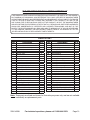
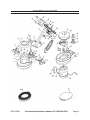
PARTS LIST
Part Description Q’ty
1 Chassis 1
2 Label 1
3A Motor (115 Volt / 60 Hz) 1
4 Circlip (#10) 2
5 Flat Washer (#10) 4
6 Spacer (#10) 2
7 Wheel 2
8 Motor Shield 1
9 Trademark 1
10 Screw Box 1
11 Handle Screw (M8 x 55) 1
12 Flat Washer (#8 x #16) 2
13 Hex Lock Nut (M8) 1
14 Screw (M5 x 18) 2
15 Plate 3
16 Locking Pin 1
17 Cord Clip 1
18 P-Clip 2
19 Cord Hook 2
20 Pop-Rivet Handle (#4) 4
21 Handle Tube 1
22 Grounding Warning Label 1
23 Screw (M5 x 40) 2
24 Trademark 1
25 Pad Screw (M4 x 12) 8
26 Front Handle 1
27 Screw (ST3.5 x 16) 2
Part Description Q’ty
28 Cord Clamp 1
29 Power Switch 1
30 Hex Nut (M4) 4
31 Warning Label 1
32 Hex Nut (M5) 4
33 Cord Protector 1
34A Power Cord 1
35 Brush Holder Pad 1
36 Bearing Core 1
37
Bearing (6006-2RS) 1
38 Spacer 2
39 Bearing Box 1
40 Plate w/Counterweights 1
41 Screw (M6 x 20) 2
42 Screw (M6 x 18) 4
43 Spacer (#6) 4
44 Flat Washer (#6) 4
45 Axle 1
46 Data Plate 1
47A
Capacitor 1
48 Capacitor Box 1
49 Screw (M4 x 6) 2
50 Sponge Pad 4
51 11” Dia. Carpet Brush (Black) 1
52 11” Dia. Floor Brush (Green/White) 1
54 12” Dia. Foam Pad (White) 1
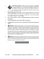
Note: Some parts are listed and shown for illustration purposes only, and are not available
individually as replacement parts.

Page 14SKU 94280
For technical questions, please call 1-800-444-3353.
47A
34A
3A
ASSEMBLY DIAGRAM

Page 15SKU 94280
For technical questions, please call 1-800-444-3353.
LIMITED 90 DAY WARRANTY
Harbor Freight Tools Co. makes every effort to assure that its products meet high
quality and durability standards, and warrants to the original purchaser that this product
is free from defects in materials and workmanship for the period of 90 days from the date
of purchase. This warranty does not apply to damage due directly or indirectly, to misuse,
abuse, negligence or accidents, repairs or alterations outside our facilities, criminal activity,
improper installation, normal wear and tear, or to lack of maintenance. We shall in no event
be liable for death, injuries to persons or property, or for incidental, contingent, special
or consequential damages arising from the use of our product. Some states do not allow
the exclusion or limitation of incidental or consequential damages, so the above limitation
of exclusion may not apply to you. THIS WARRANTY IS EXPRESSLY IN LIEU OF ALL
OTHER WARRANTIES, EXPRESS OR IMPLIED, INCLUDING THE WARRANTIES OF
MERCHANTABILITY AND FITNESS.
To take advantage of this warranty, the product or part must be returned to us with
transportation charges prepaid. Proof of purchase date and an explanation of the com-
plaint must accompany the merchandise. If our inspection verifies the defect, we will either
repair or replace the product at our election or we may elect to refund the purchase price
if we cannot readily and quickly provide you with a replacement. We will return repaired
products at our expense, but if we determine there is no defect, or that the defect resulted
from causes not within the scope of our warranty, then you must bear the cost of returning
the product.
This warranty gives you specific legal rights and you may also have other rights
which vary from state to state.
3491 Mission Oaks Blvd. • PO Box 6009 • Camarillo, CA 93011 • (800) 444-3353
-
 1
1
-
 2
2
-
 3
3
-
 4
4
-
 5
5
-
 6
6
-
 7
7
-
 8
8
-
 9
9
-
 10
10
-
 11
11
-
 12
12
-
 13
13
-
 14
14
-
 15
15


Harbor Freight Tools 94280 User manual
- Category
- Power tools
- Type
- User manual
Ask a question and I''ll find the answer in the document
Finding information in a document is now easier with AI
Related papers
-
 Finch & McLay 95378 Owner's manual
-
Harbor Freight Tools 66308 User manual
-
Chicago Electric 92156 User manual
-
Harbor Freight Tools 95288 User manual
-
Harbor Freight Tools 96811 Owner's manual
-
-
-
-
-

Other documents
-
Windsor Expert Safety Instructions
-
-
-
-
-
CHICAGO 93353 Assembly And Operating Instructions Manual
-
-
-
-