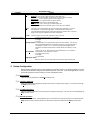
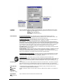
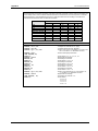
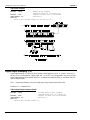
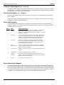
Omega OMB-NETSCAN 1500 User manual
- Category
- Measuring, testing & control
- Type
- User manual
This manual is also suitable for

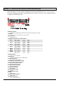
OMB-NETSCAN
Ethernet/Internet-Based
Data Logging & Control Instrument
User’s Guide
p/n
OMB-1035-0901
Rev
1.0

OMEGAnet
SM
On-Line Service
http://www.omega.com
Internet e-mail
Servicing North America:
USA:
One Omega Drive, Box 4047
Stamford, CT 06907-0047
Tel: (203) 359-1660
e-mail: [email protected]
FAX: (203) 359-7700
Canada:
976 Berger
Laval (Quebec) H7L 5A1
Tel: (514) 856-6928
e-mail: [email protected]
FAX: (514) 856-6886
For immediate technical or application assistance:
USA and Canada:
Sales Service: 1-800-826-6342 / 1-800-TC-OMEGA
SM
Customer Service: 1-800-622-2378 / 1-800-622-BEST
SM
Engineering Service: 1-800-872-9436 / 1-800-USA-WHEN
SM
TELEX: 996404 EASYLINK: 62968934 CABLE: OMEGA
Mexico and
Latin America:
Tel: (95) 800-TC-OMEGA
SM
En Espanol: (95) 203-359-7803
FAX: (95) 203-359-7807
e-mail: [email protected]
Servicing Europe:
Benelux:
Postbus 8034, 1180 LA Amstelveen, The Netherlands
Tel: (31) 20 6418405
Toll Free in Benelux: 06 0993344
e-mail: [email protected]
FAX: (31) 20 6434643
Czech Republic:
ul. Rude armady 1868
733 01 Karvina-Hranice
Tel: 420 (69) 6311899
e-mail:czech@omega.com
FAX: 420 (69) 6311114
France:
9, rue Denis Papin, 78190 Trappes
Tel: (33) 130-621-400
Toll Free in France: 0800-4-06342
e-mail: france@omega.com
FAX: (33) 130-699-120
Germany/Austria:
Daimlerstrasse 26, D-75392 Deckenpfronn, Germany
Tel: 49 (07056) 3017
Toll Free in Germany: 0130 11 21 66
e-mail: germany@omega.com
FAX: 49 (07056) 8540
United Kingdom:
25 Swannington Road,
Broughton Astley, Leicestershire,
LE9 6TU, England
Tel: 44 (1455) 285520
FAX: 44 (1455) 283912
P.O. Box 7, Omega Drive,
Irlam, Manchester,
M44 5EX, England
Tel: 44 (161) 777-6611
FAX: 44 (161) 777-6622
Toll Free in England: 0800-488-488
e-mail: uk@omega.com
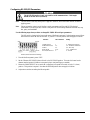
It is the policy of OMEGA to comply with all worldwide safety and EMC/EMI regulations that
apply. OMEGA is constantly pursuing certification of its products to the European New Approach
Directives. OMEGA will add the CE mark to every appropriate device upon certification.
The information contained in this document is believed to be correct but OMEGA Engineering, Inc. accepts
no liability for any errors it contains, and reserves the right to alter specifications without notice.
WARNING: These products are not designed for use in, and should not be used for, patient-connected applications.

© 1998 by IOtech, Inc. November 1998 Printed in the United States of America
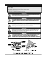
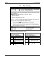
How To Use This Manual
Chapter 1: Configuring and Starting NetScan provides information to get your NetScan system up and running on
the ethernet. Includes software installation instructions.
Chapter 2: ChartViewNET Quick Start and Tutorial includes basic concepts regarding the ChartViewNET
software program, and a ChartView tutorial to quickly familiarize you with the application.
Chapter 3: General Information and Specifications gives a general description of NetScan and related hardware
including NetScan’s expansion chassis and available signal conditioning cards.
Chapter 4: ChartView Software Reference includes information regarding ChartView, ChartView Plus,
ChartViewNET, and ChartViewNET Plus. Topics include detailed explanations of the program’s pull-down
menus, toolbar icons, and keypad control options.
Chapter 5: PostView explains how to use this independent program to view charts recorded by the ChartView
programs.
Chapter 6: Calibration explains how to use ScanCal, a software-automated method of calibration, as well as how to
manually calibrate the master chassis and option cards.
Chapter 7: Hardware provides detailed information regarding NetScan hardware. The chapter includes information
regarding the front and rear panels, two-position voltage selector switch, memory addition, RS-232/422 serial
communication interfaces, digital I/O lines, external TTL connectors, signal conditioning modules, CSN/Exp
expansion chassis (option), and high current CSN/relay card (option).
Appendices
The Appendices provide programming-related information that is not necessary for users of ChartViewNET and
ChartViewNET Plus, but is useful to those wishing to write their own programs. The appendices are arranged as
follows:
Appendix A: API Commands describes the entire command set for NetScan. Syntax, parameters, interpretation, and
error codes are explained. Sections on the individual commands include their parameters, types, typical use,
related information, and a sample program excerpt.
Appendix B: Ethernet API provides information regarding ethernet-related commands.
Appendix C: Configuration Aspects for Programmers provides information on memory allocation, channel and
scan configuration, triggers, alarms, and digital I/O operation.
Appendix D: Registers, Data Formats, & Queries provides information regarding registers, data formats, status and
event reporting, and other operation-related factors.
Appendix E: NetScan Program Examples explains the program examples which are supplied on the release disk.
Typical tasks are covered including various kinds of data acquisition and alarm control.
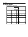
Appendix F: ASCII Code Summary summarizes ASCCII control codes and character codes.
Appendix G: NetScan Error Messages lists and describes error codes pertaining to NetScan.
Appendix H: Abbreviations
&$87,21
If equipment is used in any manner not specified in this manual, or if specification limits are
exceeded, the function of the equipment, as well as the protection provided by it, may be
impaired.

ii NetScan User’s Manual
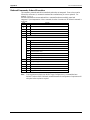
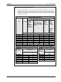
Table of Contents
1 Configuring and Starting NetScan
Overview……1-1
Inspect Your System ……1-1
Install Software ……1-2
Check and Install Hardware …… 1-2
Verify Voltage Setting ……1-2
Verify DIP Switch Setting ……1-2
Install Signal Conditioning Card(s) …..1-2
Connect Expansion Chassis (option)…..1-3
Setup for Ethernet Operation…… 1-4
Complete Hardware Setup for Ethernet
Operation…… 1-4
NetScan and TCP/IP Addressing …… 1-8
Protocol …… 1-8
IP Address …… 1-8
Sub-net Mask …… 1-8
Gateway Address …… 1-8
Configuration …… 1-9
Point-to Point Setup…… 1-9
Private LAN Setup …… 1-9
Private LAN Setup with Multiple Networks……
1-10
LAN Setup with Internet Access ……1-10
Connect Channel Signal Inputs……1-10
2 ChartViewNET QuickStart and Tutorial
Overview ……2-1
ChartViewNET, Basic Concepts ……2-1
Configuration Files ……2-1
Groups, Charts, & Channels ……2-2
Three Ways of Using
ChartViewNET
……2-3
ChartViewNET Tutorial ……2-6
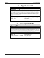
3 - General Information and Specifications
General Description…… 3-1
Operational Aspects…… 3-2
Data Handling and Triggering…… 3-2
Software and Hardware…… 3-3
NetScan Specifications…… 3-3
4 ChartView Software Reference
Overview ……4-1
Groups, Charts, & Channels ……4-2
Three Ways of Using
ChartView
……4-2
What ChartView and ChartView Plus Provide
……4-3
Main Window ……4-4
Channel Information Region ……4-6
Status Indicator Region ……4-7
Main Window Toolbar ……4-8
Group Select ……4-8
Start, Pause, and Stop Charts ……4-8
Scroll Faster & Scroll Slower ……4-8
Display Configuration ……4-9
Channel Configuration ……4-15
PostView post-acq data viewer ……4-15
Arm Acquisition ……4-15
Disarm ……4-15
Print Charts ……4-16
Main Window Pull-Down Menus ……4-16
Bar Graph, Analog, & Digital Meters …4-27
Overview ……4-27
Bar Graph Meters ……4-28
Analog Meters ……4-29
Digital Meters ……4-30
Meter Toolbars ……4-31
Meter Pull-Down Menus ……4-31
Meters Configuration Menu ……4-32
Setup Window ……4-33
Channel & Alarm Setup Dialog Box ……4-33
Acquisition Setup Dialog Box ……4-36
Channel Configuration Columns ……4-35
Alarm Configuration Columns ……4-36
Data Destination Dialog Box ……4-39
Data Destination ……4-39
Auto Re-arm (ChartView Plus only) ……4-39
Why use Auto Re-arm? ……4-40
Disabling Auto Re-arm ……4-40
Chart Setup Wizard ……4-41
Introduction ……4-41
Automatic Chart Setup with Wizard ……4-41
Bypassing Automatic Chart Setup ……4-41
5 PostView
Introduction ……5-2
Starting PostView ……5-3
Toolbar ……5-4
Channel Information Region ……5-5
Menu Items ……5-6
Understanding Groups, Charts, and
Channels ……5-7
Chart Setup Wizard ……5-7
Introduction ……5-7
Automatic Display Creation ……5-8
Display Configuration ……5-9
Editing a Display ……5-10
Manually Creating a Display ……5-12
PostView Timebase ……5-15

NetScan User’s Manual iii
6 Calibration
Introduction ……6-1
Calibration Setup ……6-1
Non-Volatile Storage of Calibration Constants
……6-2
Hardware Protected RAM ……6-2
ScanCal Software Application ……6-3
ScanCal’s Main Window ……6-3
Using ScanCal ……6-4
Interface Parameters
System Inventory
Calibration
Calibration Without ScanCal ……6-5
Password ……6-5
Calibration Mode Indicator ……6-5
Command Active Indicators ……6-5
Manual Calibration of Main Unit ……6-6
Offset Calibration of Main Unit ……6-6
Gain Calibration of Main Unit ……6-8
Manual Calibration of
Signal Conditioning Cards ……6-10
Offset Calibration of Cards ……6-10
Gain Calibration of Low Volts Cards ……6-12
Gain Calibration of High Volts Card ……6-15
Cold Junction Calibration ……6-17
7 Hardware Setup
Overview ……7-1
Front Panel ……7-1
Rear Panel ……7-2
Power Aspects ……7-3
Changing the Voltage Setting ……7-3
Replacing the AC Power Supply Fuse ……7-4
Memory Configuration ……7-4
Expanded Memory Options ……7-4
Calibration Memory Write Enable/Disable
……7-6
Ethernet Interface Configuration ……7-6
RS-232/422 Interface Configuration ……7-6
Configuring RS-322/422 Parameters …… 7-7
Serial Port Pin Connectors ……7-8
Digital I/O Lines ……7-10
Logic Levels ……7-10
Digital I/O Port Pinout ……7-10
External TTL BNC Connectors ……7-11
Signal Conditioning Cards ……7-11
CSN14/TC/P Thermocouple and Low Volts
Card with Subminiature Plugs ……7-12
CSN14/LV/ (T, B, & S) Low Voltage Cards
……7-14
CSN14/HV/S High Voltage Card with Safety
Jack Connectors ……7-15
CSN/Relay Card (for High-Current Digital-
Output) ……7-16
CSN/Relay Card Specifications ……7-17
Expansion Chassis, CSN/Exp (Option)
……7-17
Connecting the Expansion Chassis ……7-17
Automatic Channel Assignment ……7-19
Appendices
Appendix A
API Commands
Appendix B
Ethernet API
Appendix C
Configuration Aspects for
Programmers
Appendix D
Registers, Data Formats, &
Queries
Appendix E
NetScan Program Examples
Appendix F
ASCII Code Summary
Appendix G
NetScan Error Messages
Appendix H
Abbreviations

iv NetScan User’s Manual

NetScan User’s Manual,
11-16-98
Configuring and Starting NetScan 1-1
Configuring and Starting NetScan 1
Overview…… 1-1
Inspect Your System…… 1-1
Check and Install Hardware…… 1-2
Verify Voltage Setting…… 1-2
Verify DIP Switch Settings…… 1-2
Install Signal Conditioning Card(s)…… 1-2
Connect Expansion Chassis (option)…… 1-3
Setup for Ethernet Operation…… 1-4
Complete Hardware Setup for Ethernet
Operation…… 1-4
Install Software/Configure Address Settings
for Ethernet Operation…… 1-5
NetScan and TCP/IP Addressing …… 1-8
Protocol …… 1-8
IP Address …… 1-8
Sub-net Mask …… 1-8
Gateway Address …… 1-8
Configuration …… 1-9
Point-to Point Setup…… 1-9
Private LAN Setup …… 1-9
Private LAN Setup with Multiple Networks…… 1-10
LAN Setup with Internet Access ……1-10
Connect Channel Signal Inputs……1-10
For successful operation your computer needs to have the following:
•
10-Base-T Type Ethernet card and cables
•
Available COMM Port
•
PC system with Pentium
processor
•
Windows 3.1+, Windows 95, or Windows 98
•
At least 8 Mbytes of RAM for Windows 3.1+ (16 Mbytes recommended)
•
At leasr 16 Mbytes of Ram for Windows95/98 (32 Mbytes recommended)
Overview
This chapter explains how to configure NetScan for ethernet use. The chapter provides steps for making proper
connection to the ethernet and includes power up instructions. Note that Chapter 7, Hardware Reference, contains
detailed information pertaining to hardware issues, including setup for RS-232 and RS-422 operation.
Inspect Your System
If you have not already done so, carefully unpack your shipping carton and check all contents for damage which may
have occurred during shipment. Immediately report all damage to the shipping agent and your sales representative.
Retain all shipping materials in case the unit must be returned to the factory.
Each NetScan is shipped with the following:
NetScan Ethernet/Internet-Based Data Logging and Control Instrument
------------------ Signal Conditioning Card(s) pre-installed per customer order
1035-0901 NetScan User’s Manual
1035-0601
Programmed Disk Set, includes ChartViewNET Software
CN-18-50 DB50 Digital I/O Mating Connector
CA-1 Power Cable
CA-192-5 10-Base-T “straight through” ethernet cable, 5 ft.
CA-192-Adapter 10-Base-T “cross-over” adapter
FU-1-.5 1/2A, 250V, Slo Blo, 3AG for 105 - 125V power line or
FU-1-.25 1/4A, 250V, Slo Blo, 3AG for 210 - 250V power line

1-2 Configuring and Starting NetScan NetScan User’s Manual
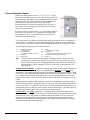
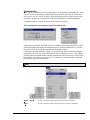
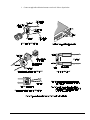
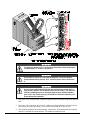
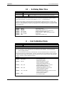
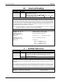
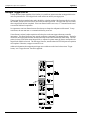
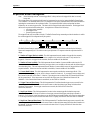
Check and Install Hardware
Depending on your order, your NetScan unit may not require all the steps under this heading. If a step does
not apply to your unit, simply go on to the next one.
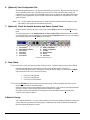
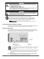
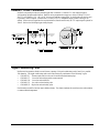
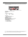
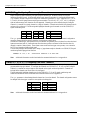
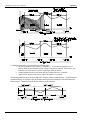
NetScan Rear Panel
Verify Voltage Setting
Based on your order, your NetScan system was set at the voltage indicated on the sticker (located on the
rear of the unit, near the power switch). Verify that the voltage value indicated on the sticker matches the
voltage of your intended AC power supply. If you need to change the voltage selection for any reason, refer
to Chapter 7’s section entitled, Power Aspects, Changing the Voltage Setting.
Verify DIP Switch Settings
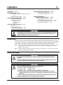
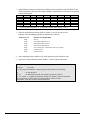
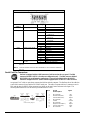
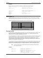
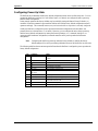
The DIP switch is located on the lower right corner of NetScan’s rear panel. Default settings are as follows.
Note that micro-switch #1 must be set to the “0” position. The IEEE position does not apply to NetScan.
Selection
COMM SELECT
HANDSHAKE (H/S)
PARITY
BAUD RATE
RS-232/422 SELECT
Micro-
Switch #
1
2,3
4,5
6,7,8
9
Setting
0 – Required for NetScan
1,0 – Hardware Handshake
0,0 – No Parity
1,1,0 – 19200 Baud
0 – RS-232 position
NetScan, Default DIP Switch Settings
The IEEE position does not apply to NetScan.

NetScan User’s Manual Configuring and Starting NetScan 1-3
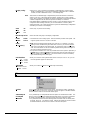
Install Signal Conditioning Card(s)
Signal conditioning cards are pre-installed per customer order. However, if you need to install a signal
conditioning card, or CSN/Relay card, perform the following steps. Repeat the steps for additional cards,
and for placing cards into the optional CSN/Exp expansion chassis, if applicable.
&$87,21
Ensure NetScan is powered down and not connected to any power source prior to
installing or removing a card. Failure to do so could cause equipment damage.
&$87,21
Use approved ESD precautions, including static-free work area and grounded wrist
strap, when handling circuit boards and electronic components. Failure to do so
could cause equipment damage due to electrostatic discharge.
&$87,21
Only one CSN/Relay card can be used in a NetScan system. Attempts to install the
CSN/Relay card in a slot other than slot #1 of NetScan’s main unit can cause
equipment damage.
The CSN/Relay card, if used, must be installed in the bottom slot of the main unit.
Aside from this requirement, cards may be installed in any slot.
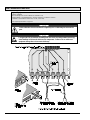
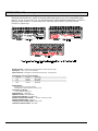
1.
Ensure NetScan is powered down and not connected to any power source.
2.
With channel labels oriented upright, carefully slide the card into the unit, and along the card support
grooves. Gently force the card to engage its edge connector with NetScan’s internal mating connector.
3.
Tighten the external screws snug, at each end of the card.
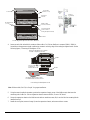
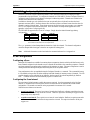
NetScan Front Panel, One of Many Possible Set-ups
Connect Expansion Chassis (option)
If you ordered a expansion chassis (CSN/Exp), please refer to Chapter 7 for installation instructions.

1-4 Configuring and Starting NetScan NetScan User’s Manual
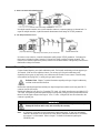
Setup for Ethernet Operation
Complete Hardware Setup for Ethernet Operation
If you want to operate your NetScan unit independent of (not-connected to) the ethernet,
refer to Chapter 7 for serial operation.
If you ordered a expansion chassis (CSN/Exp), please refer to Chapter 7 for installation
instructions.
Note 1:
The DB9 connection to
NetScan’s CONFIG Port is
required only during initial
configuration.
Note 2:
If conneting NetScan
directly to your PC’s ethernet
connection, a 10-Base-T cross-over
adapter (or a cross-over cable)
must be used.
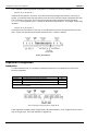
Initial Connections for Ethernet Setup
Perform the following hardware-related steps to setup NetScan for ethernet operation.
1.
If connecting NetScan directly to your PC:
(a) connect the cross-over adapter (CA-192-Adapter) to your PC’s ethernet connector
(b) connect the “straight-through” 10-Base-T type cable (CA-192-5) to NetScan’s ETHERNET Port
(c) connect the other end of the straight-through cable to the the cross-over adapter.
Option: A 10-Base-T cross-over cable may be used in place of an adapter with straight-through cable
2.
If connecting NetScan to a hub: connect a “straight-through” type 10-Base-T type ethernet cable
(CA-192-5) to NetScan’s ETHERNET Port; then connect the other end of the cable to the PC’s
ethernet hub.
3.
Connect a CA-47 cable (or equivalent DB9 cable) to NetScan’s 9-pin sub D CONFIG Port.
4.
Connect the other end (DB25 or DB9 connector end) of the CA-47 (or equivalent cable) to an available
COMM Port on your PC. Note that the PC COMM ports can be 25 pin, or 9 pin.
5.
Ensure NetScan’s Interface Selector Switch is set to the ETHERNET (up) position.
6.
Make sure NetScan’s power switch is in the “0” (OFF) position.
7.
Plug power cord CA-1 into NetScan’s power connector (located on the rear panel). Plug the other end
of the cord into an appropriate power receptacle.
8.
Turn NetScan’s power switch to the “1” (ON) position. The Power LED should light up.
At initial power-up NetScan performs automatic self-tests to ensure that it is fully functional. The rear
panel LEDs indicate errors, if they occur. Possible error conditions and their corresponding indicator light
patterns are shown in the following table. Any pattern not shown is an internal error that is not field-
serviceable; in this case, contact the factory. When only the POWER and ERROR LEDs are on, a
configuration error exists as a result of the setup information in NV-RAM.

NetScan User’s Manual Configuring and Starting NetScan 1-5
If you observe a configuration error, perform an error status query (see E? in Appendix A). If you observe
any other type of error condition, make note of the error and contact your service representative.
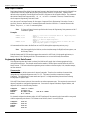
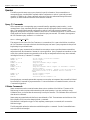
Error Condition LED Indicators
ALARM TRIGGER SCAN ERROR POWER
General Hardware Failure ON ON -Flash- ON
ROM Invalid for U22, COMM2 -Flash- ON
ROM Checksum Error for
U21 Comm1
ON -Flash- ON
ROM Checksum Error for
U22 COMM2
ON -Flash- ON
Non-Volatile RAM Error ON -Flash- ON
Dynamic RAM Error ON ON -Flash- ON
Interprocessor COM Error ON ON ON -Flash- ON
Configuration Error ON ON
If no problems are found NetScan will begin its power-up initialization. This self-test is performed each
time the unit is powered up regardless of whether power-on was caused by the power switch or the Power-
On Reset (
*R
) command.
During initialization, NetScan self test performs the following steps:
•
Checks for errors at power-up.
•
Checks the flag in the NV-RAM to determine if it should power-up with factory default
settings or a user-defined configuration.
•
Loads appropriate registers with corresponding values in NV-RAM.
•
Checks a flag to see if alarms should be enabled at power-up, and if so, enables them.
•
Loads channel configuration registers.
•
Loads program sequencer with appropriate channel configurations.
•
Resets computations processor to begin acquiring scans.
The self-test takes approximately 5 seconds to complete; after which, NetScan is ready for normal
operation.
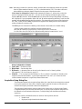
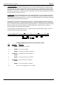
Install Software/Configure Address Settings for Ethernet Operation
Be sure you have completed the hardware-related steps on page 1-4 prior to performing
the steps below. Failure to complete the hardware-related steps will result in a
communications error.
Use Microsoft Windows Run dialog box to configure NetScan’s address and install the ChartView program
group. Direct Windows to run the
SETUP.EXE
file found on Installation Diskette 1. Follow the on-screen
dialog boxes to complete a successful installation.
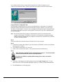
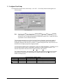
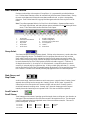
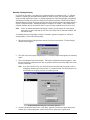
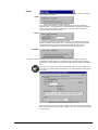
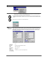
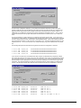
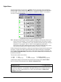
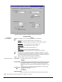
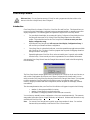
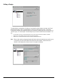
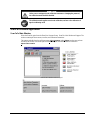
Early in the setup you will be prompted to enter your Network Interface ID Number. This number appears
on your Network Registration Sheet and must be entered to enable ChartViewNET.
Screen Prompt for Entering the Network Interface Registration ID

1-6 Configuring and Starting NetScan NetScan User’s Manual
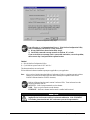
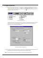
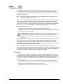
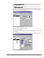
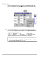
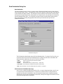
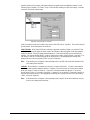
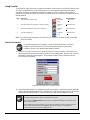
If you ordered ChartView Plus, you must enter the registration ID number as it appears on your
ChartView Plus Registration Sheet. Otherwise, press Next and continue to follow the screen prompts.
Screen Prompt for Entering the ChartView Plus ID
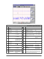
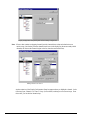
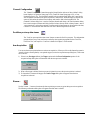
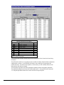
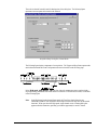
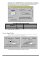
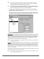
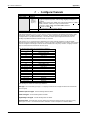
Using the NetScan Configuration Utility
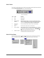
NetScan must be configured before you can use it in the ethernet mode. Configuration is accomplished
through the NetScan Configuration Utility that activates after you select “NetScan” as your device type.
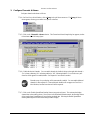
The utility’s window displays a “welcome” prior to prompting you through the required configuration steps.
The following steps appear in the utility’s screen prompts. Note that each “step” has a corresponding tab
(see following figure).
Note:
The network interface must be properly configured before NetScan can communicate with a
computer via the ethernet. The NetScan Configuration Utility application completes this task by
sending configuration settings from your computer’s serial port to the configuration port (CONFIG)
on NetScan’s Ethernet Interface.
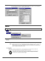
Step 1
Select an available serial communication port (COMM Port) from your computer.
Step 2
a)
Disconnect the network cable (10Base-T type) from NetScan’s ETHERNET connector on the Ethernet
Interface portion of NetScan.
b)
Cycle NetScan’s power switch “Off,” then “On.”
c)
Check (
3
) the on-screen box that states, “I have performed the actions desribed above.”
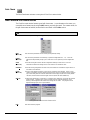
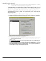
Step 3
Basic information regarding TCP/IP Addressing begins on page 1-8. The section includes
definitions and describes four different operating scenarios.
If you have any difficulty regarding address settings, please contact your network
administrator.
a)
If necessary, make changes to the address settings, then press the Apply Changes button. You may
need to refer to the TCP/IP information beginning on page 1-8, or contact your network administrator.
b)
Press the Next button (see following figure).

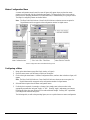
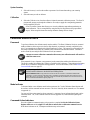
NetScan User’s Manual Configuring and Starting NetScan 1-7
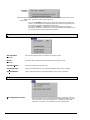
NetScan Configuration Utility, Step 3
You will receive a “>>Communications Error<<” if the NetScan Configuration Utility
fails to communicate with NetScan. Likely causes are:
1) Wrong COMM Port selected in the utility (step1).
2) Serial cable connected to wrong connector on NetScan, PC, or both.
If you received the error message, check system cable connections, correct the problem,
then return to Step 2 and perform the requested actions.
Finished
a)
Exit the NetScan Configuration Utility.
b)
Cycle NetScan’s power switch “Off” and “On.”
The ethernet interface can now be used.
Follow additional software installation prompts as applicable to your application.
Note:
After you have finished using the NetScan Configuration Utility to complete your unit’s address
settings you can remove the DB9 cable (the cable conecting the computer COMM Port to
NetScan’s Ethernet Interface CONFIG connector).
NetScan’s Ethernet Interface panel contains 3 indicator LEDs. These indicators have the
following meanings when lit:
ACTIVITY
– Data is being transmitted over the ethernet.
LINK
– There is a good connection to the ethernet.
ETHERNET
– NetScan’s ethernet interface mode is enabled and functional.
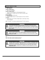
&$87,21
A flashing ETHERNET LED indicator (located on NetScan’s Ethernet Interface panel)
implies that the NetScan unit could have an internal malfunction. If the ETHERNET
LED flashes, please turn the unit “Off” and contact your service representative.

1-8 Configuring and Starting NetScan NetScan User’s Manual
NetScan and TCP/IP Addressing
Protocol
The NetScan uses TCP/IP (Transport Control Protocol/Internet Protocol) for communications over the
ethernet. You can access NetScan devices from virtually anywhere in the world since the World Wide Web
uses this same protocol.
TCP/IP addressing consists of three parameters: the IP address, the Sub-net Mask, and the Gateway
Address. Each of these parameters consists of four different numbers which range from 0 to 255. The
numbers are typically represented in a dotted decimal format, for example: 192.88.247.11.
IP Address
The IP (Internet Protocol) is a device address that is unique to one specific device located on the network.
A device’s IP address can not be shared by any other device on the network. The only restrictions on the IP
address are:
1) the first number must be between 127 and 255
2) the last number must be between 1 and 254.
Sub-net Mask
The Sub-net Mask determines how many addresses are on the network. Note that Class C networks consist
of up to 256 addresses; and are quite common. For a Class C Network the Sub-net Mask would be
255.255.255.0. All computers on the network must have the same subnet mask.
Gateway Address
A gateway address is needed to a access a device (gateway, or router) that can route traffic from one
network to another. The gateway address is the actual address of the gateway (router) device.

NetScan User’s Manual Configuring and Starting NetScan 1-9
Configuration
There are four basic network scenarios that pertain to NetScan ethernet operation. Note that proper TCP/IP
configuration is extremely important, and you must obtain TCP/IP addressing parameters before
configuring the protocol. The rules for configuration differ for each scenario as follows:
1) Point-to-Point Setup
Point-to-Point Setup
In the Point-to-Point scenario, NetScan is connected directly to a PC using a crossover cable. Since there is
no actual network the only requirements are:
1)
The first three numbers of NetScan’s IP address must match the first three numbers of the computer’s
IP address.
2)
The sub-net mask should be set to 255.255.255.0
3)
The gateway address can be omitted.
Example
TPC/IP address set to 192.88.247.1
Sub-net mask set to 255.255.255.0
2) Private Local Area Network (LAN) Setup
Private LAN Setup
In this simple LAN scenario, NetScan is connected to a network with several PC’s using the TCP/IP
protocol. These networks typically use a system administrator or network analyst to address TCP/IP issues.
For private LAN setups, requirements are:
1)
A unique IP address must be assigned to the NetScan device
2)
The first three numbers of the IP address must be the same for all devices on the network
3)
The sub-net mask should be set to 255.255.255.0
4)
The gateway address can be omitted
Example
TPC/IP address set to 192.88.247.1 for NetScan device
First three numbers of all network devices are 192.88.247
Sub-net mask is set to 255.255.255.0

1-10 Configuring and Starting NetScan NetScan User’s Manual
3) Private LAN Setup with Multiple Networks
Private LAN with Multiple Networks
In multiple-network scenarios, two or more networks connect to a common gateway via ethernet hubs. In
regard to multiple networks, a qualified network administrator should assign all TCP/IP parameters.
4) LAN Setup with Internet Access
LAN Setup with Gateway Access to Internet
In internet access scenarios, a network adminstrator usually assigns TCP/IP parameters. Configuring for
this scenario is identical to that of scenario 2 (Private LAN Setup), with the following exception: The
internet access scenario requires the gateway address to be set to the address of the gateway (router) device
that handles routing to the internet.
Connect Channel Signal Inputs
Connect channel inputs to your signal conditioning cards. Each signal conditioning card can support up to
16 Channels. With use of the expansion chassis, you can have up to 8 signal conditioning cards.
Depending on the type(s) of cards used, your connections will be made via one or more of the following:
screw terminal, mini-plug, BNC, or safety jack type input connector.
Reference Note:
Chapter 7 contains information regarding each type of signal conditioning
card that can be used with NetScan.
NetScan has eight digital input lines and thirty-two digital output lines available on the rear panel DB-50
connector (see pin-out, below).
Each digital output line will drive five (5) standard TTL loads. All digital input lines are one-eighth (0.125)
TTL loads. All inputs are protected against damage from high static voltage. Normal precautions should be
taken to limit the input voltages to the range of 0.0 to 5.3 volts. All digital I/O lines are referenced to the
connector’s ground pins.
&$87,21
Do not exceed the 0.0 to 5.3 volts levels described above. Exceeding these levels may
damage the NetScan unit in a way not covered by the warranty.
Note:
A CSN/Relay is available for high current alarm output applications. If used, this card must be
installed in the bottom slot of the NetScan’s main chassis. Installation instructions for CSN/Relay
are on page 1-3 of this manual. Refer to chapter 7 for detailed information regarding the
CSN/Relay card.

NetScan User’s Manual Configuring and Starting NetScan 1-11
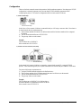
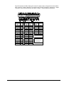
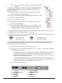
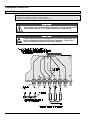
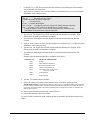
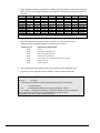
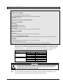
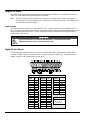
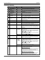
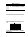
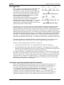
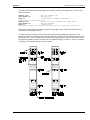
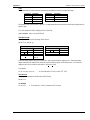
The following figure and table identify pin locations for outputs, inputs, and grounds associated with the
DB50 connector. Outputs 1 through 32 are typically used for alarms 1 through 32, respectively. Outputs
1 through 16 can be used with the relay card option. Chapter 7 contains additional information.
DB50 Pin Descriptions
Output
Signal
Pin
No.
Output
Signal
Pin
No.
Input
Signal
Pin No.
11 17 39
115
234 18 23
248
318 19 7
332
42 20 40
416
535 21 24
549
619 22 8
633
73 23 41
717
836
24 25 850
920
25 9
10 4
26 42
11 37
27 26
Ground Pins
12 21
28 10 12, 13, 14,
13 5
29 43 28, 29, 30, 31,
14 38
30 27 45, 46, 47
15 22
31 11
16 6
32 44

1-12 Configuring and Starting NetScan NetScan User’s Manual
−
Notes

NetScan User’s Manual,
11-16-98
2-1
ChartViewNET Quick Start and Tutorial 2
Overview ……2-1
ChartViewNET, Basic Concepts ……2-1
Configuration Files ……2-1
Understanding Groups, Charts, & Channels ……2-2
Three Ways of Using ChartViewNET ……2-3
ChartViewNET Quick Start ……2-3
ChartViewNET Tutorial ……2-6
Overview
This chapter provides the steps to connect, power up, and run NetScan using the TCP/IP protocol.
Although there are many ways to configure NetScan, this Startup is intended for a simple setup. In addition
to the following steps, this chapter includes a section on basic concepts and a ChartViewNET tutorial. These
are provided to help you gain a better understanding of the ChartView program. Note that Chapter 7,
Hardware Setup, contains detailed information pertaining to hardware issues and includes RS-232 and
RS-422 information.
ChartViewNET, Basic Concepts
An understanding of several basic concepts will help you master ChartViewNET more quickly, and should
be understood before proceeding with the tutorial.
ChartViewNET refers to a ChartView program that has the network feature of the program
activated, much like ChartView Plus refers to a ChartView program that has the enhanced
chart feature of the program activated. The NET and Plus features are each activated by
separate registration ID codes; thus it is possible to have ChartViewNET Plus (when both
codes are used). For ease of discussion, this chapter’s use of the term ChartView also refers
to ChartViewNET; and ChartView Plus refers to ChartViewNET Plus.
Configuration Files
ChartView makes use of one or more “user transparent” configuration files. Configuration files maintain
information regarding various aspects of your setup, serving as an initialization file for subsequent
ChartView startups. These files can be recognized by their
.cvw
extensions.
Note:
When you run ChartView for the very first time there will be no configuration file; however, one
will automatically generate and be saved after each use of the program.

2-2 ChartView Quick Start and Tutorial NetScan User’s Manual
ChartView uses
Chartvw.cvw
as a default configuration file. This file maintains a location for ChartView
configuration information including:
•
Device Interface Mode
•
Hardware Configuration
•
Channel Settings:
⇒
Channel Enable/Disable (On/Off)
⇒
Type
⇒
Label
⇒
Units
⇒
Alarm Settings (Limits)
⇒
Hysteresis Setting
•
Acquisition Configuration
•
Data Storage Settings
The configuration file ensures that when you restart ChartView, it will be in the same state upon your last
exit. This means that the
Chartvw.cvw
file will be an updated copy of the configuration file you are using
at the time you exit ChartView.
It is not catastrophic if a configuration file is deleted, since it is a simple task to start ChartView when no
configuration file exists. This is described in the tutorial.
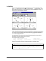
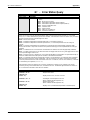
Understanding Groups, Charts, & Channels
When starting the program with no configuration file present, a feature called Chart Setup Wizard is
automatically activated to assist you with your setup. To make the best use of Chart Setup Wizard you need
to understand the relationship of Groups, Charts, and Channels.
Note:
ChartView and Chart Setup Wizard are detailed in Chapter 4 of this manual.
Group
. “Group” refers to a group of charts. ChartView makes use of one chart group. ChartView Plus
allows up to 64 groups, depending on the capabilities of your PC, but only displays data from one chart
group at a time.
Chart
. “Chart” refers to display area which reflects real-time channel data values and can be scrolled at
various rates. One chart can display data from up to four channels. In addition, each chart will display real-
time information for a selected channel. You can assign up to 16 charts per group.
Channel
. “Channel” refers to a signal channel. You can have up to 4 channels assigned to one chart.
Channels will be displayed in units of °C, °F, °K, °R, mV, V, or in user-defined units, depending on the
configuration and type of signal conditioning card used. NetScan’s signal conditioning card options are
detailed in Chapter 7.
Page is loading ...
Page is loading ...
Page is loading ...
Page is loading ...
Page is loading ...
Page is loading ...
Page is loading ...
Page is loading ...
Page is loading ...
Page is loading ...
Page is loading ...
Page is loading ...
Page is loading ...
Page is loading ...
Page is loading ...
Page is loading ...
Page is loading ...
Page is loading ...
Page is loading ...
Page is loading ...
Page is loading ...
Page is loading ...
Page is loading ...
Page is loading ...
Page is loading ...
Page is loading ...
Page is loading ...
Page is loading ...
Page is loading ...
Page is loading ...
Page is loading ...
Page is loading ...
Page is loading ...
Page is loading ...
Page is loading ...
Page is loading ...
Page is loading ...
Page is loading ...
Page is loading ...
Page is loading ...
Page is loading ...
Page is loading ...
Page is loading ...
Page is loading ...
Page is loading ...
Page is loading ...
Page is loading ...
Page is loading ...
Page is loading ...
Page is loading ...
Page is loading ...
Page is loading ...
Page is loading ...
Page is loading ...
Page is loading ...
Page is loading ...
Page is loading ...
Page is loading ...
Page is loading ...
Page is loading ...
Page is loading ...
Page is loading ...
Page is loading ...
Page is loading ...
Page is loading ...
Page is loading ...
Page is loading ...
Page is loading ...
Page is loading ...
Page is loading ...
Page is loading ...
Page is loading ...
Page is loading ...
Page is loading ...
Page is loading ...
Page is loading ...
Page is loading ...
Page is loading ...
Page is loading ...
Page is loading ...
Page is loading ...
Page is loading ...
Page is loading ...
Page is loading ...
Page is loading ...
Page is loading ...
Page is loading ...
Page is loading ...
Page is loading ...
Page is loading ...
Page is loading ...
Page is loading ...
Page is loading ...
Page is loading ...
Page is loading ...
Page is loading ...
Page is loading ...
Page is loading ...
Page is loading ...
Page is loading ...
Page is loading ...
Page is loading ...
Page is loading ...
Page is loading ...
Page is loading ...
Page is loading ...
Page is loading ...
Page is loading ...
Page is loading ...
Page is loading ...
Page is loading ...
Page is loading ...
Page is loading ...
Page is loading ...
Page is loading ...
Page is loading ...
Page is loading ...
Page is loading ...
Page is loading ...
Page is loading ...
Page is loading ...
Page is loading ...
Page is loading ...
Page is loading ...
Page is loading ...
Page is loading ...
Page is loading ...
Page is loading ...
Page is loading ...
Page is loading ...
Page is loading ...
Page is loading ...
Page is loading ...
Page is loading ...
Page is loading ...
Page is loading ...
Page is loading ...
Page is loading ...
Page is loading ...
Page is loading ...
Page is loading ...
Page is loading ...
Page is loading ...
Page is loading ...
Page is loading ...
Page is loading ...
Page is loading ...
Page is loading ...
Page is loading ...
Page is loading ...
Page is loading ...
Page is loading ...
Page is loading ...
Page is loading ...
Page is loading ...
Page is loading ...
Page is loading ...
Page is loading ...
Page is loading ...
Page is loading ...
Page is loading ...
Page is loading ...
Page is loading ...
Page is loading ...
Page is loading ...
Page is loading ...
Page is loading ...
Page is loading ...
Page is loading ...
Page is loading ...
Page is loading ...
Page is loading ...
Page is loading ...
Page is loading ...
Page is loading ...
Page is loading ...
Page is loading ...
Page is loading ...
Page is loading ...
Page is loading ...
Page is loading ...
Page is loading ...
Page is loading ...
Page is loading ...
Page is loading ...
Page is loading ...
Page is loading ...
Page is loading ...
Page is loading ...
Page is loading ...
Page is loading ...
Page is loading ...
Page is loading ...
Page is loading ...
Page is loading ...
Page is loading ...
Page is loading ...
Page is loading ...
Page is loading ...
Page is loading ...
Page is loading ...
Page is loading ...
Page is loading ...
Page is loading ...
Page is loading ...
Page is loading ...
Page is loading ...
Page is loading ...
Page is loading ...
Page is loading ...
Page is loading ...
Page is loading ...
Page is loading ...
Page is loading ...
Page is loading ...
Page is loading ...
Page is loading ...
Page is loading ...
Page is loading ...
Page is loading ...
Page is loading ...
Page is loading ...
Page is loading ...
Page is loading ...
Page is loading ...
Page is loading ...
Page is loading ...
Page is loading ...
Page is loading ...
Page is loading ...
Page is loading ...
Page is loading ...
Page is loading ...
Page is loading ...
Page is loading ...
Page is loading ...
-
 1
1
-
 2
2
-
 3
3
-
 4
4
-
 5
5
-
 6
6
-
 7
7
-
 8
8
-
 9
9
-
 10
10
-
 11
11
-
 12
12
-
 13
13
-
 14
14
-
 15
15
-
 16
16
-
 17
17
-
 18
18
-
 19
19
-
 20
20
-
 21
21
-
 22
22
-
 23
23
-
 24
24
-
 25
25
-
 26
26
-
 27
27
-
 28
28
-
 29
29
-
 30
30
-
 31
31
-
 32
32
-
 33
33
-
 34
34
-
 35
35
-
 36
36
-
 37
37
-
 38
38
-
 39
39
-
 40
40
-
 41
41
-
 42
42
-
 43
43
-
 44
44
-
 45
45
-
 46
46
-
 47
47
-
 48
48
-
 49
49
-
 50
50
-
 51
51
-
 52
52
-
 53
53
-
 54
54
-
 55
55
-
 56
56
-
 57
57
-
 58
58
-
 59
59
-
 60
60
-
 61
61
-
 62
62
-
 63
63
-
 64
64
-
 65
65
-
 66
66
-
 67
67
-
 68
68
-
 69
69
-
 70
70
-
 71
71
-
 72
72
-
 73
73
-
 74
74
-
 75
75
-
 76
76
-
 77
77
-
 78
78
-
 79
79
-
 80
80
-
 81
81
-
 82
82
-
 83
83
-
 84
84
-
 85
85
-
 86
86
-
 87
87
-
 88
88
-
 89
89
-
 90
90
-
 91
91
-
 92
92
-
 93
93
-
 94
94
-
 95
95
-
 96
96
-
 97
97
-
 98
98
-
 99
99
-
 100
100
-
 101
101
-
 102
102
-
 103
103
-
 104
104
-
 105
105
-
 106
106
-
 107
107
-
 108
108
-
 109
109
-
 110
110
-
 111
111
-
 112
112
-
 113
113
-
 114
114
-
 115
115
-
 116
116
-
 117
117
-
 118
118
-
 119
119
-
 120
120
-
 121
121
-
 122
122
-
 123
123
-
 124
124
-
 125
125
-
 126
126
-
 127
127
-
 128
128
-
 129
129
-
 130
130
-
 131
131
-
 132
132
-
 133
133
-
 134
134
-
 135
135
-
 136
136
-
 137
137
-
 138
138
-
 139
139
-
 140
140
-
 141
141
-
 142
142
-
 143
143
-
 144
144
-
 145
145
-
 146
146
-
 147
147
-
 148
148
-
 149
149
-
 150
150
-
 151
151
-
 152
152
-
 153
153
-
 154
154
-
 155
155
-
 156
156
-
 157
157
-
 158
158
-
 159
159
-
 160
160
-
 161
161
-
 162
162
-
 163
163
-
 164
164
-
 165
165
-
 166
166
-
 167
167
-
 168
168
-
 169
169
-
 170
170
-
 171
171
-
 172
172
-
 173
173
-
 174
174
-
 175
175
-
 176
176
-
 177
177
-
 178
178
-
 179
179
-
 180
180
-
 181
181
-
 182
182
-
 183
183
-
 184
184
-
 185
185
-
 186
186
-
 187
187
-
 188
188
-
 189
189
-
 190
190
-
 191
191
-
 192
192
-
 193
193
-
 194
194
-
 195
195
-
 196
196
-
 197
197
-
 198
198
-
 199
199
-
 200
200
-
 201
201
-
 202
202
-
 203
203
-
 204
204
-
 205
205
-
 206
206
-
 207
207
-
 208
208
-
 209
209
-
 210
210
-
 211
211
-
 212
212
-
 213
213
-
 214
214
-
 215
215
-
 216
216
-
 217
217
-
 218
218
-
 219
219
-
 220
220
-
 221
221
-
 222
222
-
 223
223
-
 224
224
-
 225
225
-
 226
226
-
 227
227
-
 228
228
-
 229
229
-
 230
230
-
 231
231
-
 232
232
-
 233
233
-
 234
234
-
 235
235
-
 236
236
-
 237
237
-
 238
238
-
 239
239
-
 240
240
-
 241
241
-
 242
242
-
 243
243
-
 244
244
-
 245
245
-
 246
246
-
 247
247
-
 248
248
-
 249
249
-
 250
250
-
 251
251
-
 252
252
-
 253
253
-
 254
254
-
 255
255
-
 256
256


Omega OMB-NETSCAN 1500 User manual
- Category
- Measuring, testing & control
- Type
- User manual
- This manual is also suitable for
Ask a question and I''ll find the answer in the document
Finding information in a document is now easier with AI
Related papers
-
Omega Engineering 1400 User manual
-
Omega HH506RA Owner's manual
-
-
-
-
-
-
-
-
Other documents
-
Intermatic EMKB Installation guide
-
ALTENEW Poinsettia and Berries Stamp Set Operating instructions
-
 Wiley 978-0-470-04400-1 Datasheet
-
Visioneer 4000 User manual
-
Uncategorized B&K Precision DAS220-BAT/DAS240-BAT Portable Data Recorders User manual
-
AL-KO SENSABRAKE Removal Instructions
-
IDEAL INDUSTRIES NaviTEK II User manual
-
Ideal Networks SignalTEK NT User manual
-
Futek IPM525 User manual
-
Electro-Voice Example Owner's manual
