
INSTALLATION
INSTRUCTION
INSTALLATION INSTRUCTIONS FOR
559374
ECONOMIZERS USED WITH Q5SN / Q6SP 090-120
P6 / R6 120 UNITS
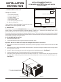
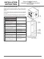
Fig ure 1
ENTHALPY SENSOR
CONTROL PACKAGE (STEP 3)
DAMPER MOTOR
MULLIONS
RETURN AIR OPENING
INSERT THE SIDE FLANGES INTO
THE UNIT STANDING SEAMS
Figure 2
FORM# 571C-0411 (571C-0610)
1
I - SHIP PING AND PACK ING LIST
Package 1 of 1 contains:
1 - Economizer Assembly
1 - Fresh Air Hood w/ Filter
1 - Control Package
1 - Barometric Relief Hood
1 - Filter Access Panel
2 - Wire Nut (For Mixed Air Sensor)
16 - #10 x ½ x 16 Hex Tec
Check contents for shipping damage. Contact the last carrier
immediately if any shipping damage is found.
II - AP PLI CA TION
Economizers are used with Q5SN/Q6SP/P6/R6 units for automatic sensor-controlled introduction of outdoor air into the
system through an electro-mechanically controlled damper. Outdoor air is mixed with the buildings return air to
economically improve indoor air quality and aide in reducing energy costs.
Economizer slides into horizontal return air opening. Mixed air sensor, TB11, and enthalpy control board relay are shipped
in economizer and must be relocated to the unit's filter section. Intake and exhaust hoods are packaged with economizers
and installed according to instructions below.
III - ECONOMIZER IN STAL LA TION
1. Disconnect all power to unit.
2. Cut and discard wire tie securing wire bundle to the damper motor
Important - DO NOT cut other wires. Inspect for damaged connections or loose wires.
3. Remove box of controls to be installed over the assembly containing the logic control board and mixed air sensor. See
Figure 1.
4. Remove from box the logic control board and wire bundle. Cut wire tie securing the bundle of wires to logic control
board and mixed air sensor.
5. Locate S1, the unit's economizer connection and remove the installed dummy plug. See Figure 3.
6. Connect economizer jack S2 to economizer plug P2 on the economizer assembly.
7. Route wiring to the right side of the economizer and slide it into the unit. Insert economizer side flanges into the unit
standing seams. Using existing screws from bottom of discarded panel to secure economizer bottom flange to unit.
See Figure 2.

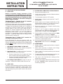
TB11 BOARD AND LOGIC CON TROL
FIL TERS
INTAKE AIR
EXHAUST AIR
Figure 3
DAMPER MOTOR
ENTHALPY SENSOR
S1 UNIT JACK
MIXED AIR SENSOR
DOWN FLOW APPLICATION
Figure 4
FILTER ACCESS
SCREW TO SIDE MULLIONS
FRESH AIR HOOD
BAROMETRIC
RELIEF HOOD
12. Install barometric relief hood in front
of exhaust air opening.
13. Install fresh air hood in front of intake
opening.
14. Slide filter access panel underneath
top of unit and secure to mullions.
a. For heatpump units refer to
Section IV before restoring the
unit power.
15. Restore power to unit and check for
proper damper operation (See
System Check section).
12. Install barometric relief hood to
return duct over the opening in
duct.
13. Install fresh air hood in front of
intake opening.
14. Slide filter access panel
underneath top of unit and
secure to mullions.
a. For heatpump units refer to
Section IV before restoring
the unit power.
15. Restore power to unit and check
for proper damper operation
(See System Check section).
BAROMETRIC RELIEF HOOD
FRESH AIR HOOD
Figure 5
8. Position logic control board in filter access area as
shown in Figure 3. Secure control board with two
#10-16 x ½ screws.
9. Insert mixed air sensor tube through the mounting
hole into the supply air compartment. Secure using
two #10-16 x ½ screws. See Figure 3.
10. Connect economizer plug P1 to unit jack S1 on units
economizer control panel.
11. Verify that wire harnesses are secure and will not
interfere with economizer vane and linkage
operation, or with a filter change out
Note: Leave unit dummy plug (from Step 5) in the
unit control panel for later use if the
economizer needs to be by passed.
FILTER ACCESS
INSTALLATION
INSTRUCTION
INSTALLATION INSTRUCTIONS FOR
559374
ECONOMIZERS USED WITH Q5SN / Q6SP 090-120
P6 / R6 120 UNITS
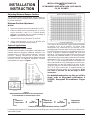
NOTE: FOR THIS APPLICATION, HORIZONTAL
DUCT KIT #547881 IS REQUIRED.
HORIZONTAL APPLICATION
2
CUT HOLE
559374 - 31" x 18
3
8
SUPPLY DUCT
30 x 16
3
8
RETURN DUCT
31 x 18 ¾

IV – HEAT PUMP SET UP PRO CE DURES
A. Q5SN Series
Notice to Installer: Proper operation of this
economizer when used on Q5SN Series 7.5 and 10 Ton
Package Heat Pump systems is dependent on the type
thermostat installed with the unit. Identify which type
thermostat is connected to unit before making any
wiring changes if needed.
Ther mo stat Type 1 – Sep a rate "O" and "B" ter mi nals
for se lect ing Re vers ing Valve Con trol
Q5SN Series Heat Pump units are factory pre-wired for
economizers connected in conjunction with a 2 Stage Heat
/ 2 Stage Cool thermostat that utilize the "O" terminal to
energize the reversing valve(s) when the thermostat
"System Switch" is set in the "Cool" mode and has a
separate "B" terminal supplied with 24 VAC when the
thermostat "System Switch" is in the Off, Heat, or
Emergency Heat” mode. With "B" energized the
economizer is automatically locked out during heating
operation. It holds the outdoor fresh air damper at the
minimum position setting only.
Ther mo stat Type 2 –Sin gle "O/B" ter mi nal for
se lect ing Re vers ing Valve Con trol
If the thermostat has only one terminal, "O/B", for
determining if Heat or Cool mode energizes the Reversing
Valve(s), the following heat pump unit low voltage wiring
changes MUST
be made: (Refer to the unit wiring diagram
for identification)
1. DISCONNECT MAIN POWER TO THE UNIT.
2. Thermostat - Select the "Cool" mode to energize the
Heat Pump unit’s reversing valve(s).
3. Heat Pump Relay - Located to the left of the Defrost
Board in the unit’s main control panel.
l Reverse connections of the Orange and Yellow
wires on Heat Pump Relay terminals 1 and 4.
l Reverse connections of the White and Blue wires
on Heat Pump Relay terminals 3 and 6.
4. Low Voltage Terminal Board - Jumper "O" and "B"
terminals. Located in the Electric Heat Section of unit.
B. Q6SP Series
The Q6SP Series heatpumps are factory wired for use with
an"O" terminal that is energized in cooling mode. These
units do not require or utilize a "B" terminal signal. Do not
alter the factory wiring of the Q6SP units for use with this
economizer
3
INSTALLATION
INSTRUCTION
INSTALLATION INSTRUCTIONS FOR
559374
ECONOMIZERS USED WITH Q5SN / Q6SP 090-120
P6 / R6 120 UNITS
V - SYS TEM CHECK AND START UP PRO CE DURES
1. Disconnect main power to unit.
2. Install jumper on auxiliary contacts of blower contactor
in main unit control box.
3. Turn thermostat control to “OFF” position.
4. Install jumper on damper motor terminals T and T1.
See Figure 8.
5. Restore power to unit. Damper should drive to fully
opened position (requires 1 ½ minutes for full travel).
Observe travel for proper damper operation.
6. Disconnect power to unit. Damper should spring
return to closed position.
7. Remove T and T1 jumper on damper motor, then
restore power to unit. Adjust minimum vent position on
potentiometer on damper motor. See Figure 8.
8. Set the outdoor air enthalpy change overpoint. Refer
to Figure 6 and the instructions on Page 4.
9. Disconnect power to unit and remove jumper on
auxiliary contacts of blower contactor in main unit
control box. Restore power to unit.
10. Set the minimum damper position. See instructions on
Page 5 and 6 and the chart on the last page.
VI - MAIN TE NANCE
1. Damper motor is prelubricated and does not require
further lubrication.
2. Make visual inspection of dampers and linkage
assemblies during routine maintenance.
3. Filters should be checked periodically and cleaned
when necessary.
4. The washable filters supplied with the economizer can
be cleaned with water and a mild detergent.
5. Take note of "Air Flow Direction" marking on filter
frame when reinstalling.
6. If filter must be replaced, filter of like kind and size must
be used. DO NOT replace permanent filters with
throwaway type filters.

OP ER A TION
A. Cool ing Mode
1. On a call for cooling, with ambient temperature and
humidity above enthalpy control setpoint, damper will
open to minimum vent position.
2. On a call for cooling, with ambient temperature and
humidity suitable for cooling, enthalpy control will shift
stage one control to outside air and shift stage two
thermostat to first stage compressor. Damper will
modulate to control supply air temperature at 55° F
(13° C). If additional cooling is required, compressor
one may be energized through second stage of
thermostat.
B. Heat ing Mode
1. On a call for heat damper will open to the minimum
vent position only.
Figure 6
Set ting the Out door Enthalpy Change over
Point
The enthalpy control senses both temperature and
humidity or the heat content of the outside air. It controls
the amount of outdoor air brought into the system. When
the heat content of the outside air is below control setpoint,
the control modulates outdoor dampers to meet cooling
needs of the building. When the heat content rises above
control setpoint, the control closes outdoor dampers to
minimum position. The recommended setpoint is “A”. If
Economizer is allowing air which is too warm or too humid
to enter the system, control may be changed to a lower
setpoint (B, C, or D). Refer to Figure 6.
Differential Enthalpy Settings
For units equipped with a differential enthalpy sensor, refer
to the instructions include in the 920233 accessory kit.
INSTALLATION
INSTRUCTION
INSTALLATION INSTRUCTIONS FOR
559374
ECONOMIZERS USED WITH Q5SN / Q6SP 090-120
P6 / R6 120 UNITS
4

5
INSTALLATION
INSTRUCTION
INSTALLATION INSTRUCTIONS FOR
559374
ECONOMIZERS USED WITH Q5SN / Q6SP 090-120
P6 / R6 120 UNITS
Op tional Ap pli ca tions
Re mote Min i mum Po si tion Con trol
Remote control of outdoor air dampers is desirable when
potential exists for temporary additional ventilation. The
potentiometer in W7459 controls damper minimum
position. Adding S963B1128 Remote Manual
Potentiometer allows occupants to open dampers beyond
minimum position for additional ventilation. Connect
potentiometer as shown in Figure 7.
Figure 7
S963B1128 Remote Minimum Position Potentiometer
used with W7459 for remote damper control.
Ad just ing Min i mum Damper Po si tion
The minimum position potentiometer keeps outdoor air
damper from closing completely during system operation
to provide ventilation.
Min i mum Po si tion Ad just ment
W7459A
1. Disconnect mixed air sensor from terminals T and T1.
2. Make sure either factory-installed jumper is in place
across terminals P and P1 or if remote damper
positioner is required, that it is wired according to
Figure 7 and turned fully clockwise.
3. Connect 24 Vac across terminals TR and TR1.
4. Adjust potentiometer on face of W7459 with
screwdriver to desired minimum position.
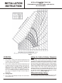
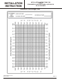
This chart can also be used for measuring the percentage
of outside air on an air handler. The same three
temperatures are measured per the formulas on the
preceding page. Lines are drawn on the chart using a ruler.
As with the formulas this chart is most effective if there is at
least a 10 degree F difference between the return and
outside air. This will typically require either a warm or cold
day rather than moderate weather. It is more accurate to
measure outside air percentage on a day when the outside
temperature is 10°F (-12°C) rather than on a day when it is
70°F (21°C). If the temperature difference between the
return and outside air is only a few degrees, a small error in
measurements can alter the results by as much as 50%
using this method. If the temperature difference is 40 or
50°F (22 or 28°C) small errors in measurement do not
substantially affect the results of the calculations. A full
size chart is provided on the last page of these
instructions.
For detailed instructions on the use of this
chart, refer to Honeywell publication #
63-8594, Honeywell Economizers. Pages
12-13.
For design requirements for CFM per person for all building types, refer to ASHRAE standard 62.1 section 6 and/or local or
state building codes.
Re turn Air
Tem per a ture
% of
Re turn Air
Out side Air
Tem per a ture
% of
Out side Air
Tem per a ture
of Mixed Air
+
x x
=
Formula for Adjusting the Minimum Position Control

6
INSTALLATION
INSTRUCTION
INSTALLATION INSTRUCTIONS FOR
559374
ECONOMIZERS USED WITH Q5SN / Q6SP 090-120
P6 / R6 120 UNITS
1. Measure the return air temperature.
2. Measure the outside air temperature.
3. Draw a line from the return air temperature to the
outside air temperature.
4. Measure the mixed air temperature in multiple
locations and determine the average.
5. Draw a line down from the mixed air temperature to the
point where it intersects the first line.
6. Draw a line from the point of intersection to the outside
air percentage on the left side of the chart.
According to the results from this chart this air handler is
supplied with 26% outside air. If the total supply volume is
20,000 cubic feet per minute (cfm) (566 m
3
/min) then:
0.26 X 20,000 cfm of total supply air equals 5,200 cfm of
outside air (147 m
3
/min).
This indicates that when the measurements were done on
this air handler the total volume of outside air in the mixed
air was 5,200 cfm of outside air (147 m
3
/min).

7
INSTALLATION
INSTRUCTION
INSTALLATION INSTRUCTIONS FOR
559374
ECONOMIZERS USED WITH Q5SN / Q6SP 090-120
P6 / R6 120 UNITS
Figure 9 - W7459A
Figure 8 - M7415A
DAMPER ACTUATOR
Check out Procedure Proper Response
1. a. Dis con nect power at TR and TR1. ----
b. Dis con nect Jumper P to P1.
c. Jumper TR to 1.
d. Jumper T1 to T.
e. If con nected, re move C7400 Solid State
Enthalpy Sen sor from ter mi nals S
O
and +.
En sure fac tory-in stalled 620 ohm re sis tor is
connected to terminals S
R
and +.
LED is off.
f. Apply power (24 Vac) to terminals TR and TR1. Motor is in closed position.
2. a. Disconnect factory-installed 620 ohm resistor
from terminals S
R
and +.
LED turns on (A model only, for D model,
go to step 3).
Motor drives toward open.
3. a. To simulate high and low enthalpy (single
enthalpy sensor), reconnect factory- installed
620 ohm resistor from terminals S
R
and +.
Connect 1.2K ohm 4074EJM Checkout
Resistor across terminals S
O
and +
----
b. Turn enthalpy setpoint potentiometer to "A". LED turns on, indicating low enthalpy.
Motor drives toward open.
c. Turn enthalpy setpoint potentiometer to "D". LED turns on, indicating high enthalpy.
Motor drives toward closed.
d. Disconnect the 1.2K ohm checkout resistor. ----
4. a. To verify sensor operation, reconnect the + lead
of outdoor enthalpy sensor to the + terminal of
W7459
----
b. Connect a DC milliammeter between terminal
S
O
of the W7459A and terminal S of the
enthalpy sensor. (Positive meter lead to
terminal S of the enthalpy sensor.)
Milliammeter indication is between 3 and
25 mA if sensor is operating properly.
If milliammeter indicates zero, the sensor
may be wired backwards.
c. When using differential enthalpy, check the
return air enthalpy sensor by connecting a DC
milliammeter between terminal S
R
of the
W7459A and terminal S of the return air
enthalpy sensor. (Positive meter lead to
terminal S of the enthalpy sensor.)
Milliammeter indication is between 3 and
25 mA if sensor is operating properly.
If milliammeter indicates zero, the sensor
may be wired backwards
CHECK OUT AND TROU BLE SHOOT ING
Check the W7459 for proper operation. Table 1 describe how to
simulate various environmental conditions. Make necessary minor
adjustments to the minimum position until desired operation is
obtained.
If the economizer system does not operate properly, check individual
components of the system according to the instructions provided with
each device.
If the other components operate properly when disconnected from the
W7459, but the system (as a whole) does not, replace the W7459.

INSTALLATION
INSTRUCTION
INSTALLATION INSTRUCTIONS FOR
559374
ECONOMIZERS USED WITH Q5SN / Q6SP 090-120
P6 / R6 120 UNITS
8
C7046C Air Temperature Sensors
resistance versus temperature.
Approximate dimensions of C7046C Air Temperature Sensor in in. (mm).
C7400A Sensor output current
vs. relative humidity
Approximate dimensions of C7400A Solid State Enthalpy Sensor
C7650A Solid State Temperature Sensor in in. (mm)

Mod u lat ing Economizer
Q5SN / Q6SP 090-120
P6 / R6 120 (559374)
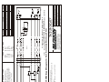
Notes:
1. Y2 must be en er gized for Stage 1 com pres sor to op er ate dur ing economizer op er a tion.
2. Re lays 1K and 2K ac tu ate when the out door air enthalpy is higher than the enthalpy set point A-D
on the the W7459A Logic Mod ule.
3. 1S is an elec tronic switch which closes when pow ered by a 24 VAC in put.
4. Fac tory in stalled 620 Ohm, 1 Watt, 5% re sis tor should be re moved only when a sec ond C7400
Enthalpy Sen sor is added to SR and + for dif fer en tial enthalpy con trol.
Date: June 22, 2010
Supersedes: 06-07-10
Drawn by: MGL
Unit #: 47-314-11
Di a gram#: 4731411W
Ap proved by:
WIRE COLOR CODE
BLK Black
BLU Blue
BRN Brown
GRN Green
ORN Orange
RED Red
VIO Violet
WHT White
YEL Yellow
COMPONENT CODE
C7046C Mixed Air Sensor
C7400A Fresh Air Sensor
M7415A Damper Actuator 24V
P1/S1 Plug/Cap Economizer
P2/S2 Plug/Cap Economizer
TB-11 Terminal Board
W7459A Logic Module
Re vi sion Change Date
A Changed mixed air sensor 11-07-07
B
Changed wire lengths 06-07-10
C Added S2/P2 plugs back in 06-18-10
HARNESS DETAIL
E# = WIRE END DESIGNATION
E2 STUD #6 18 Ga. Wire
E3 Female ¼ Quick Disc.
E4 Male ¼ Quick Disc. Insul
E6 Wire Nut Size 73B
HAR NESS ENDS AT
(P1) ECONO MIZER
PLUG
See Unit Wiring Diagram for Connections at S1
CONNECTOR & CONTACT CONFIGURATION
P1 - (303908) PLUG & (303912) PIN
S2/P2 - (303903/303904) CAP/PLUG & (303913/303912) SOCKET/PIN

SUPERSEDES 06-21-10
MAY 18, 2011
NEIEC11
Outside Air Percentage Chart
INSTALLATION
INSTRUCTION
INSTALLATION INSTRUCTIONS FOR
559374
ECONOMIZERS USED WITH Q5SN / Q6SP 090-120
P6 / R6 120 UNITS
10
© Nortek Global HVAC
, LLC 2015. All Rights Reserved.
-
 1
1
-
 2
2
-
 3
3
-
 4
4
-
 5
5
-
 6
6
-
 7
7
-
 8
8
-
 9
9
-
 10
10


Unbranded Q6SP Installation guide
- Type
- Installation guide
- This manual is also suitable for
Ask a question and I''ll find the answer in the document
Finding information in a document is now easier with AI
Related papers
-
Unbranded Economizers for 559375 Installation guide
-
-
-
Reznor R6GP Installation guide
-
Broan CO2 Sensor With Honeywell, 547848 Installation guide
-
Broan R8GE Installation guide
-
Broan Economizers for 558870 Downflow Installation guide
-
-
-
Reznor R6GN Installation guide
Other documents
-
Carrier CAECOMZR001B00 User manual
-
Honeywell C7650A User manual
-
Trane BAYRLAY004A Installer's Manual
-
-
-
Reznor R7TQ Installation guide
-
Mammoth R7TQ Installation guide
-
-
Bryant 599C User manual
-
Carrier BAYECON103AA-AB-AC Installation guide