
Printed in the United States 224D3383P001 31-49005 03-13 GE
1
Installation Instructions
Single Door Drain Pan Kit (WR74X10355)
MODELS: ZIF*360NX* AND ZIR*360NX*
Questions? Call 1-800-GE-CARES (1-800-432-7237)
PARTS PROVIDED:
Single Door Drain Pan Kit (WR74X10355)
Drain Pan Assembly
Baffle Template
Evaporator Cover Assembly
#10 Self-tapping Screw
10 Watt Heater
Harness
TOOLS REQUIRED:
#2 Phillips Screwdriver with
6” Extension for Screwdriver and
1/4 Head-head attachment
RTV 102
Flat-head Screwdriver
Scraper
PPE REQUIRED:
Safety Goggles
Safety Gloves
Padding/Support for knees
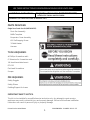
IMPORTANT SAFETY NOTICE:
This kit is to be installed by a qualified service technician only. Any attempt to repair a major
appliance may result in personal injury and property damage. Failure to follow these installation
instructions can result in personal injury or property damage.
USE THESE INSTRUCTIONS FOR MONOGRAM SINGLE-DOOR UNITS ONLY

Printed in the United States 224D3383P001 31-49005 03-13 GE
2
PROCEDURE:
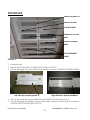
Picture 1
1. Unplug the unit.
2. Remove SNACK PAN SHELF FZ {WR17X12679}. (See PICTURE 1)
3. Pull out, disengage clips, and pull off of the slide rail to remove COVER IM ASM {WR32X10804}.
4. Pull out and upward to remove SNACK PAN ASM {WR32X10078}. (See Picture 1)
5. Pull out, disengage clips (Refer to Picture under Step 3), and pull off of the slide rail to remove
SUPPORT SNACK PAN ASM {WR72X10325}.
SNACK PAN ASM
COVER IM ASM
SNACK PAN SHELF FZ
Left Side Clip is pushed upward. Right Side Clip is pushed downward.
SHOWCASE LID PAN
ASM
COVER ICE BUCKET
ASM
VEG PAN BASKET
ASMS

Printed in the United States 224D3383P001 31-49005 03-13 GE
3
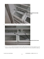
6. Pull out to remove two STRIP SD FZ VEG PAN {WR02X13223}.
7. Remove screw and WASHER SHOWCASE PIVOT {WR01X10046} (these will be put back) from side
nearest unit wall to allow SHOWCASE LID PAN ASM {WR32X10720} to be removed from bushing.
STRIP SD FZ VEG PAN
SUPPORT SNACK PAN
ASM

Printed in the United States 224D3383P001 31-49005 03-13 GE
4
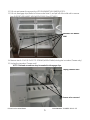
8. Push inwards at sides in back and dislodge from bushing (if bushing falls, put it back on the wall
of the cabinet) to remove Left {WR32X10119} and Right SHOWCASE LID PAN ASM
{WR32X10720}. (See PICTURE 1)
9. Pull out and upward to remove COVER ICE BUCKET ASM {WR32X10728}. (See PICTURE 1)
10. Pull out and upward to remove VEG PAN WIRE ASM {WR21X10209}.
11. Pull out, disengage clips (Refer to Picture under Note 2), and pull off of the slide rail to remove
Left {WR72X10324} and Right SUPPORT BASKET ASM {WR72X10323}.
Screw to be removed
Washer to be removed
VEG PAN WIRE ASM
SUPPORT BASKET ASM

Printed in the United States 224D3383P001 31-49005 03-13 GE
5
12. Pull out and upward to remove four VEG PAN BASKET ASM {WR32X10121}.
13. Pull out, disengage clips (Refer to Picture under Note 2), and pull off of the slide rail to remove
four SUPPORT VEG BASKET ASM {WR72X10200}. (See PICTURE 1)
14. Remove two 8-32 X 5/8" PH SS TCS SCREWS {WR01X10484} holding the ice maker. (Freezer only)
15. Unplug the icemaker. (Freezer only)
NOTE: Flathead screwdriver may be needed to disengage clips.
SUPPORT VEG BASKET
ASM
Screws to be removed
Unplug icemaker here

Printed in the United States 224D3383P001 31-49005 03-13 GE
6
16. Remove icemaker assembly and set it aside. (Freezer only)
17. Remove eight #10-16 X 1/2 TAPPING SCREWS holding the center divider assembly. (These will be
reused)
18. Pull out to remove DIVIDER CENTER ASM {WR72X10320}.
19. Use screw driver to remove seven SELF DRILL TRIM P SCREWS holding the evaporator cover.
Save fasteners for reuse.
20. Remove EVAP COVER ASM {WR74X10355} and discard.
Center Divider Assembly
Screws to be removed

Printed in the United States 224D3383P001 31-49005 03-13 GE
7
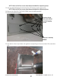
21. Unplug 9-pin connector of HARNESS HEATERS TOD {WR09X10180} from back wall of the unit.
NOTE: Flathead screwdriver may be needed to disengage clips.
22. Unplug Defrost heater {WR51X10113} from the HARNESS HEATERS TOD {WR09X10180}.
23. Unclip thermodisc and remove HARNESS HEATERS TOD {WR09X10180} (Harness can be
discarded).
24. Use driver to remove four SELF DRILL TRIM P SCREWS holding the catch evaporator trough.
Save fasteners for reuse.
Screws to be removed
Unplug these
harness connections
Unclip thermodisc and
remove.

Printed in the United States 224D3383P001 31-49005 03-13 GE
8
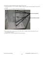
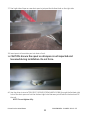
25. Remove CATCH EVAPORATOR TROUGH {WR17X12711}. (This will be put back later)
26. Use driver to remove four #10X1\2 PH SMS SCREWS {WD02X0295} holding the Evaporator in
place.
27. Pull Evaporator forward slightly to work behind it.
28. Use driver to remove four TRIM (SELF TAPPING) SCREWS holding the drain baffle in place.
Catch Evaporator Trough
Screws to be removed
Screws to be removed

Printed in the United States 224D3383P001 31-49005 03-13 GE
9
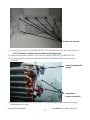
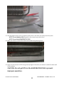
29. Use scraper to separate the gasket of the drain baffle from the back wall of the unit.
30. Remove DRAIN BAFFLE {WR17X12683}.
NOTE: Remove any pieces of the gasket that tear and stick to the back wall of the unit
31. Remove DRAIN PAN {WR17X11016}.
32. Use the TRIM (SELF TAPPING) SCREWS to screw the baffle template in place using the four lower
holes.
Drain Baffle
Screws to be removed

Printed in the United States 224D3383P001 31-49005 03-13 GE
10
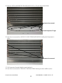
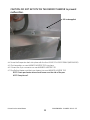
NOTE: Wait until all four screws have been started before tightening them.
33. Use hex-head attachment to drive the four #10 Screws in the 4 upper holes.
NOTE: Wait until all four screws have been started before tightening them.
34. Remove the TRIM (SELF TAPPING) SCREWS from the baffle template.
35. Discard the baffle template.
36. Use electric driver to put holes in the gasket corresponding to the screw holes of the new drain
pan.
Location of new
holes to be drilled
with Self-tapping
screws.
TRIM (SELF TAPPING)
SCREWS

Printed in the United States 224D3383P001 31-49005 03-13 GE
11
37. Peel right side of tape on new drain pan to just past the farthest hole on the right side.
38. Insert spout of new drain pan into drain of unit.
39. CAUTION: Ensure the spout on drainpan is not impacted and
loosened during installation. Do not force.
40. Use the driver to start a TRIM (SELF TAPPING) SCREW {WR01X10188} through the farthest right
hole of the drain pan and into the farthest right hole that was just drilled into the back wall of
the unit.
NOTE: Do not tighten fully.

Printed in the United States 224D3383P001 31-49005 03-13 GE
12
41. Peel the tape further until it is past the next hole on the drain pan and screw into place.
NOTE: Do not tighten fully (Repeat for the remaining screw holes.)
NOTE: Do not bend EVAPORATOR FINS.
42. Wait until all four screws have been started before tightening them.
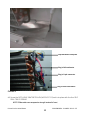
43. Apply a small amount of RTV along the top edge of the drain pan where it meets the back wall
of the cabinet.
CAUTION: Do not get RTV on the EVAPORATOR FINS to prevent
improper operation.

Printed in the United States 224D3383P001 31-49005 03-13 GE
13
CAUTION: DO NOT GET RTV ON THE DEFROST HEATER to prevent
malfunction.
44. Screw the Evaporator back into place with the four #10X1\2 PH SMS SCREWS {WD02X0295}.
45. Clip thermodisc on new HARNESS HEATERS TOD into place.
46. Connect the 9-pin connector on new HARNESS HEATERS TOD.
47. Plug Defrost heater and drain pan heater into new HARNESS HEATERS TOD.
NOTE: Drain pan heater wires should come over the side of the pan.
NOTE: See picture 2
RTV to be applied

Printed in the United States 224D3383P001 31-49005 03-13 GE
14
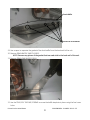
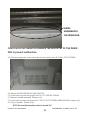
Picture 2
48. Screw the CATCH EVAP ORATOR TROUGH {WR17X12711} back into place with the four SELF
DRILL TRIM P SCREWS.
NOTE: Slide under new evaporator trough instead of over).
Clip thermodisc into place
Plug in Defrost heater
Plug in 9-pin connector
Plug in Drain Pan Heater

Printed in the United States 224D3383P001 31-49005 03-13 GE
15
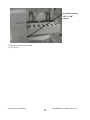
CAUTION: DO NOT BEND OR CHANGE THE GEOMETRY OF THE DRAIN
PAN to prevent malfunction.
49. Take new evaporator cover and screw into place with seven SELF DRILL TRIM P SCREWS.
50. Replace DIVIDER CENTER ASM {WR72X10320}.
51. Screw back into place using eight #10-16 X 1/2 TAPPING SCREWS.
52. Replace icemaker assembly. (Freezer only)
53. Screw back into place using two 8-32 X 5/8" PH SS TCS SCREWS {WR01X10484}. (Freezer only)
54. Plug in icemaker. (Freezer only)
NOTE: Be sure that icemaker switch is turned “On”.
SLIDES
UNDERNEATH
THE DRAIN PAN

Printed in the United States 224D3383P001 31-49005 03-13 GE
16
55. Replace drawers and baskets.
56. Plug in unit.
Turn switch from the
“OFF” to “ON”
position.

31-49005
WR74X10355

Universal Keywords: Div46 Src363 GE General Electric Mechtech
Document Specific Keywords: Instruction Sheet
Date: 101116
Document Name: 31-49005
Subject: GE Monogram Refrigerator/Freezer Single Door Drain Pan Kit Instructions
Models: ZIR360NXALH ZIR360NXARH ZIRS360NXALH ZIRS360NXARH
ZIRP360NXALH ZIRP360NXARH ZIF360NXALH ZIF360NXARH ZIFS360NXALH
ZIFS360NXARH ZIFP360NXALH ZIFP360NXARH REF0413
-
 1
1
-
 2
2
-
 3
3
-
 4
4
-
 5
5
-
 6
6
-
 7
7
-
 8
8
-
 9
9
-
 10
10
-
 11
11
-
 12
12
-
 13
13
-
 14
14
-
 15
15
-
 16
16
-
 17
17
-
 18
18


GE ZIFS360NXALH Installation guide
- Type
- Installation guide
- This manual is also suitable for
Ask a question and I''ll find the answer in the document
Finding information in a document is now easier with AI
Other documents
-
Enwork Proxi 2.0 & Proxi Plus User guide
-
Delfield ASM Series Product information
-
Scotsman KBT43 - Use with ID200, ID250 and C0322, C0522, F0522, F0822, F1222, F1522, N0422, N0622, N0922, N1322 Operating instructions
-
-
-
-
 Cornelius P/N 629087911 User manual
-
 Cornelius P/N 629083204 User manual
-
KitchenAid KSBP25INSS03 User manual
-

