Page is loading ...

INSTALLATION &
OPERATION MANUAL
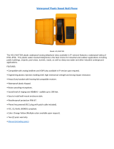
VCH10W & VCH10Y VOLTAGE CONVERTER

2
IMPORTANT & SAFETY INSTRUCTIONS
SAVE THESE INSTRUCTIONS — This manual contains important safety and operating
instructions for the battery charger.
VOLTAGE CONVERTER PRECAUTIONS
1. Do not expose the voltage converter to rain or snow unless it is a sealed model.
2. Use of an attachment not recommended or sold by the manufacturer may result in a risk
of re, electric shock, or injury to persons.
3. Do not disassemble the voltage converter; return it to the manufacturer or an authorized
service center when service or repair is required. Incorrect reassembly may result in a
risk of electric shock or re. Voltages of up to 350 volts are present inside the voltage
converter anytime it is connected to input power, even if it is switched off.
4. To reduce risk of electric shock, unplug the voltage converter from the DC power source
before attempting any maintenance or cleaning. Turning off controls will not reduce this
risk.
5. Never place the voltage converter directly above a battery; gases from battery will
corrode and damage the voltage converter.
6. Never allow battery acid to drip on the voltage converter.
Medical Equipment Notice
Analytic Systems does not recommend the use of their products in life support
applications where failure or malfunction of this product can be reasonably
expected to cause failure of the life support device or to signicantly affect its
safety or effectiveness. Analytic Systems does not recommend the use of any
of its products in direct patient care. Examples of devices considered to be life
support devices are neonatal oxygen analyzers, nerve stimulators (whether
used for anesthesia, pain relief, or other purposes), auto-transfusion devices,
blood pumps, debrillators, arrhythmia detectors and alarms, pacemakers,
hemodialysis systems, peritoneal dialysis systems, neonatal ventilator
incubators, ventilators for both adults and infants, anesthesia ventilators, and
infusion pumps as well as any other devices designated as “critical” by the U.S.
FDA.

3
TABLE OF CONTENTS
• Front Cover, Product Photo and Title
• Product warnings and advisories
• Table of Contents
• Description/Overview of product
• Main Parts
• Operation instructions
• Mounting Instructions
• Connection instructions
• Options
• Faults
• Specications
• Warranty
Revised - September 29, 2016
Copyright (2005-2016) Analytic Systems Ware (1993) Ltd.

4
Introduction
The VCH10W Step Down series of Voltage Converters supply up to 10 amps continuous and
12 amps peak current at 12, 24, 36 or 48 volts from any higher voltage between 20 and 80
volts DC in an IP66 rated watertight and EMC shielded enclosure for use in automotive, heavy
equipment, marine, industrial, rail or alternative energy environments.
The standard VCH10W model offers a Deutsch connector on a pigtail input/output cable, and
is designed to be water resistant to IP66.
The VCH10Y is an upgraded version with the same connections that is individually tested to
meet IP67.
The all surface mount high frequency design offers higher reliability, higher efciency (more
than 91%), more power (up to 544 watts at 48 VDC Out and minimum size. Two LED indicators
show the presence of input power, and when the output current exceeds the continuous
rating.
The unit has reverse input protection, output current limiting, output short circuit protection
and output over-voltage protection.

5
Main Parts
Front Panel
1. Deutsch DT04-4P Input/Output
connector on pigtail
2. Input Power Good LED
3. Overload LED
3
2
1

6
Operation
To turn the unit on, simply turn on your source of power. The Input Power LED will illuminate
to indicate the presence of input power. The overload LED will illuminate if the output current
exceeds the continuous rating of the unit.
Mounting
Mount the unit and allow at least 1 inch
of clearance for adequate cooling.
Input and Output Connections
This unit is equipped with a watertight gland
and short 4 conductor pigtail terminated with
a Deutsch DT04-4P connector. The mating
connector is also supplied, but without
cable. The plug pin out is shown in the table
below.
PIN NAME DESCRIPTION
1 POSITIVE INPUT (red)
2 NEGATIVE INPUT (black)
3 NEGATIVE OUTPUT (black)
4 POSITIVE OUTPUT (orange)
Connect the input pins to the power source, and the output pins to the load, making sure
to observe the correct polarity of the connections. If the input is connected in reverse, the
protection fuse will blow, and must be replaced by the dealer or an electronics technician.
4.64
0.21
5.91
2.15
7.0±1.0
Installation
orange
4
black
3
1 red
2 black

7
ROHS (European) Option (E Option)
Load Share Option (D Option)
IP67 (Waterproof Tested) Option (Y Option)
Consistent with military standards, this unit is normally manufactured using lead based solder.
However, this unit can be built to ROHS lead free standards, identied internally by a red
colored printed circuit board by adding the E option. This is a no charge option, but can add 2-4
weeks to the delivery of an order.
Two or more units may be congured for load sharing if they are equipped with the optional
output isolation diodes. The output current is reduced to the Continuous rating for units with
the D option.
This is the same unit as the VHC10W, except each unit is individually tested to comply with
the IP67 rating of withstanding 1 meter immersion for 30 minutes with no ingress of moisture.

8
This unit has 2 LED indicators to help diagnose simple problems.
INPUT POWER Indicates that power is being received by the unit
If the LED is not on, check with a voltmeter that there is power at the
connections.
Check that the polariy is correct, Positive to Pin 1 and Negative to Pin
2. If the power is reversed, the unit is not damaged, but the input fuse
must be replaced by a service technician experienced in Surface Mount
Technology.
OVERLOAD Indicates that the output current exceeds the continuous rating of the unit:
If this happens frequently, reduce the load connected to the unit.
Troubleshooting

9
Specications
Input Voltages
MODEL VCH10W(Y)-12 VCH10W(Y)-24 VCH10W(Y)-32 VCH10W(Y)-36 VCH10W(Y)-48
Input Volts 20 - 80 VDC 30 - 80 VDC 40 - 80 VDC 45 - 80 VDC 60 - 80 VDC
Output Voltages
Output Volts Nominal 12 VDC 24 VDC 32 VDC 36 VDC 48 VDC
Actual Volts 13.6 VDC 27.2 VDC 36.3 VDC 40.8 VDC 54.4 VDC
Output Amps 10 Amps Continuous, 12 Amps Peak
Dissipation 12 Watts
Efciency 91.9% 95.8% 96.8% 97.1% 97.8%
Electrical
Input Ripple and Noise <100 mV Peak to Peak
Output Ripple and Noise < 50 mV Peak to Peak
Transient Response <300 mV for 50% Load Step Change
Regulation (Line & Load) < +/- 0.5%
Emissions Meets MIL-STD-461F
Mechanical
Dimensions 6.20 in / 15.8 cm Long x 4.91 in / 12.5 cm Wide x 2.15 in / 5.5 cm High
Clearance 1.0 in / 2.5 cm all around
Weight 0.62.0 lb / 0.28 kg
Material and Finish Diecast Aluminum with O-Ring and EMC Gaskets, Black Powder Coat Finish
Mounting Wall or shelf mount
Connections VCHW - Deutsch DT04-4P on 15cm Pigtail; Mating Connector Included
Shock and Vibration Designed to meet MIL-STD-810G
Environmental and Safety
Operating Temperature Range -40°C to +55°C @ maximum output
Humidity 0 - 95% Relative Humidity (non-condensing) with standard conformal coating
Ingress Protection W versions - Built to meet IP66, Y versions - tested to meet IP67
Audible Noise NONE 0db @ 3ft
Typical Service Life > 10 years (87,600 hrs)
Isolation
Input - Case and Output - Case 1500 VDC
Input - Output - common negative
Warranty TWO years parts and labor
Safety Built to meet CSA 22.2.107.1 & UL458

10
Page intentionally left blank

11
Limited Warranty
1. The equipment manufactured by Analytic Systems Ware (1993) Ltd. (the “Warrantor”) is warranted to be free
from defects in workmanship and materials under normal use and service.
2. This warranty is in effect for:
a. 3 Years from date of purchase by the end user for standard products offered in our catalog.
b. 2 Years from date of manufacture for non-standard or OEM products
c. 1 Year from date of manufacture for encapsulated products.
3. Analytic Systems will determine eligibility for warranty from the date of purchase shown on the warranty card
when returned within 30 days, or
a. The date of shipment by Analytic Systems, or
b. The date of manufacture coded in the serial number, or
c. From a copy of the original purchase receipt showing the date of purchase by the user.
4. In case any part of the equipment proves to be defective, the Purchaser should do the following:
a. Prepare a written statement of the nature of the defect to the best of the Purchasers knowledge, and
include the date of purchase, the place of purchase, and the Purchasers name, address and telephone
number.
b. Call Analytic Systems at 800-668-3884 or 604-946-9981 and request a return material authorization
number (RMA).
c. Return the defective part or unit along with the statement at the Purchasers expense to the Warrantor;
Analytic Systems Ware (1993) Ltd., 8128 River Way, Delta, B.C., V4G 1K5, Canada.
5. If upon the Warrantor’s examination the defect proves to be the result of defective material or workmanship,
the equipment will be repaired or replaced at the Warrantor’s option without charge, and returned to the
Purchaser at the Warrantor’s expense by the most economical means. Requests for a different method of return
or special handling will incur additional charges and are the responsibility of the Purchaser.
6. Analytic Systems reserves the right to void the warranty if:
a. Labels, identication marks or serial numbers are removed or altered in any way.
b. Our invoice is unpaid.
c. The defect is the result of misuse, neglect, improper installation, environmental conditions, non-
authorized repair, alteration or accident.
7. No refund of the purchase price will be granted to the Purchaser, unless the Warrantor is unable to remedy the
defect after having a reasonable number of opportunities to do so.
8. Only the Warrantor shall perform warranty service. Any attempt to remedy the defect by anyone else shall
render this warranty void.
9. There shall be no warranty for defects or damages caused by faulty installation or hook-up, abuse or misuse of
the equipment including exposure to excessive heat, salt or fresh water spray, or water immersion except for
equipment specically stated to be waterproof.
10. No other express warranty is hereby given and there are no warranties that extend beyond those described
herein. This warranty is expressly in lieu of any other expressed or implied warranties, including any implied
warranty of merchantability, tness for the ordinary purposes for which such goods are used, or tness for a
particular purpose, or any other obligations on the part of the Warrantor or its employees and representatives.
11. There shall be no responsibility or liability whatsoever on the part of the Warrantor or its employees and
representatives for injury to any person or persons, or damage to property, or loss of income or prot, or any
other consequential or resulting damage which may be claimed to have been incurred through the use or sale of
the equipment, including any possible failure of malfunction of the equipment, or part thereof.
12. The Warrantor assumes no liability for incidental or consequential damages of any kind

DESIGNED AND MANUFACTURED BY
800-668-3884
604-946-9983
www.AnalyticSystems.com
8128 River Way
Delta, BC V4G 1K5 | Canada
Battery Chargers • Inverters • Power Supplies • Voltage Converters
/