Page is loading ...

Texmate, Inc. Tel. (760) 598-9899 • www.texmate.comBX-35-PROCESS manual (d0090) Page 1Texmate, Inc. Tel. (760) 598-9899 • www.texmate.com Page 1
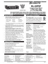
The BX-Series have a matching DIN case style
that is complementary to the Leopard and Tiger
family of meters. BX-Meters are the OEM’s
choice for switchboard and process indication.
Each model is dedicated to a specific application
and designed for quick and easy installation.
General FeaturesCompatibility
Specifications
Typical Application Connections
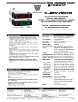
BX-35-PROCESS
4-20mA / 0-10V process
Easily user scaled, this meter is ideal for
4-20mA process loop / 0-10V measurement
and indication in any engineering unit of
measure.
The BX-35-PROCESS is cost-efective 4-20mA process loop / 0-10V
measuring meter. It is easily user adjustable to any reading between
-1999 and +1999 without component changes. The unique set of Signal
Conditioning Components incorporated in this meter, enables the use of
a simple two step scaling and calibration pro- cedure, which eliminates
the back and forth interaction between zero and span settings, which is
often required to calibrate less finely engineered products.
BX-Series
Input Configuration: ........ Series connection to 4-20mA process loop
or Single ended 0-10V DC.
Full Scale Ranges: .......... User adjustable to any scaling between
-1999 to +1999
A/D Converter: .............. 12 bit dual slope
Accuracy: ...................... ±(0.05% of reading + 3 counts)
Temp. Coeff.: ................. 100 ppm/°C (Typical)
Warm up time: ............... 2 minutes
Conversion Rate: .......... 3 conversions per second (Typical)
Display: ..........................
3 1/2 digit 0.56" Red LED display (std)
,
0.56” GREEN or Super Bright RED are
optional.
Range -1999 to 1999 counts.
Decimal Selection: ........ Header under face plate, X•X•X•X
Positive Overrange: ...... 1 (MSD) is displayed with all other digits blank.
Power Supply: ............... AC/DC Auto sensing wide range supply
PS1 (std) ....................
85-265 VAC, 50-400Hz / 95-300 VDC @1.5W
PS2 .............................
15-48 VAC,50-400Hz / 10-72 VDC @4.0W
Operating Temp.: .......... 0 to 50 °C
Storage Temp: ............... –20 °C to 70 °C.
Relative Humidity: ........ 95% (non condensing)
Case Dimensions: ........ 1/16 DIN Bezel: 96x24mm (3.78”x0.95”)
Depth behind bezel 122.2 mm (4.83")
Plus 12.7mm (0.5”) for Right-angled
connector..
Weight: ...........................7 oz., 9 oz when packed.
Certification: .................. UL Listed.
BX-Series, the OEMs choice for switchboard and process indication
BX-35-ACA ............
AC amps, Scales RMS (True RMS Opt.). (5 Amp Internal Shunt), 3.5digit
BX-35-ACV
..................
AC volts, Scaled RMS (True RMS Opt.). 199.9/300V AC Header
....................................Selectable Ranges, 3.5 digit
BX-35-DCA
.................
DC mV ±50mV, ±100mV, ±200mV Header Selectable Ranges, 3.5 digit
BX-35-DCV
.............. DC volts ±2V/±20V/±200V Header Selectable Ranges, 3.5 digit
BX-35-PROCESS
..... Process 4 to 20mA (100.0), easily user scalable, 3.5 digit w/Exc. opt
BX-35-HZ
.................
AC Line Frequency 15.0Hz to 199.9Hz. Up to 300V AC input, 3.5 digit
BX-35-TC-KF or JF
K or J Thermocouple with °F, optional °C, 3.5 digit
BX-35-RTD-F
................100Ω platinum RTD, 3 or 4 wire, °F in 1° resolution, optional °C ,3.5 digit
BX-35-PRESSURE
....
Pressure, Load Cell 20mV/2mV/V, 5/10V Exc 4-wire 3.5 digit
BX-45-ACA ............
AC amps, Scales RMS (True RMS Opt.). (5 Amp Internal Shunt), 4.5digit
BX-45-ACV
..................
AC volts, Scaled RMS (True RMS Opt.). 199.99/300.0V AC Header
....................................Selectable Ranges, 4.5 digit
BX-45-DCA
.................
DC mV ±50mV, ±100mV, ±200mV Header Selectable Ranges, 4.5 digit
BX-45-DCV
.............. DC volts ±2V/±20V/±200V Header Selectable Ranges, 4.5 digit
BX-45-PROCESS
..... Process 4 to 20mA (100.00), easily user scalable, 4.5 digit w/Exc. opt
BX-45-TC-KF
........... K Thermocouple with °F, optional °C, 4.5 digit
BX-45-TC-JF
........... J Thermocouple with °F, optional °C, 4.5 digit
BX-45-RTD-F
................100Ω platinum RTD, 3 or 4 wire, °F in 1° resolution, optional °C ,4.5 digit
BX-45-PRESSURE
........
Pressure, Load Cell 20mV/2mV/V, 5/10V Exc 4-wire 4.5 digit
3 1/2 Digit with 0.56” LEDs
in a 1/16 DIN Case
4 to 20mA Process Loop Measurement
Order IP02, if you require the loop
excitation voltage (24VDC@100mA)
to be supplied by the meter.
24V
External
Loop Supply
Common
ZERO
SPAN
Oset PROCESS 4/20 mA
0
+
_
Other devices can be
added to the loop.
Direction
Of
Current
<Decrease Zero Increase >
<Decrease Span Increase >
Range
HI
LO
OFF
ON
24V EXC
Fully User Scalable
PIN 2
PIN 1
PIN 3
+_
ID01:
DC Volts, 2/20/200V/Custom w/24V DC Exc
Custom
200V
20V
2V
ON
OFF
24V Exc
24V
Exc
< Decrease Span Increase >
SPAN
DC VOLTS
PIN 1
PIN 2
PIN 3
Custom
200V
20V
2V
ON
OFF
24V Exc
24V
Exc
< Decrease Span Increase >
SPAN
ZERO
DC VOLTS
PIN 1
PIN 2
PIN 3
ID05: DC Volts 2/20/200/Custom V DC with Offset
and 24V Exc.
0
+
_
Offset

Texmate, Inc. Tel. (760) 598-9899 • www.texmate.comPage 2 BX-35-PROCESS manual (d0090)
Component Layout
Pins 1 to 3 - Input
Pin 9 - Hold: If this pin is left unconnected the meter will
operate in a free running mode. When this pin is connected
to the Common Pin 11, the meter display will be latched. A/D
conversions will continue, but the display will not be updated
until Pin 9 is disconnected from Pin 11.
Pin 10 - Display Test: When this pin is connected to the
Common Pin 11, all segments of the display light up and 1888
is displayed. This is used to detect any missing segments in
the display.
Pin 11 - Common: To Hold, Test or Dim the display, the
re spec tive pins have to be connected to this Common Pin.
Pin 12 - Dim/Blank: When this pin is connected to the
Common Pin 11 the display is blanked out. If it is connected
through an external 1KΩ pot, the display may be dimmed.
Pin 14 & 15 - AC/DC Power Input: These pins are the power
pins of the meter and they only accept a special polarized
screw terminal plug that can not be inserted into any other
input socket. The standard meter has a auto sensing AC/DC
power supply that operates from 85-265 VAC/95-300 VDC
(PS1 Std). An optional isolated low voltage power supply that
operates from 15-48 VAC/10-72 VDC (PS2) is also available.
Pin Descriptions
Connector Pinouts
15 to 48 VAC
10 to 72 VDC
85 to 265 VAC
95 to 300 VDC
HOLD
TEST
DIM / BLANK
COMMON
981 2 3 4 5 6 10 11 12 14 15
AC
Neutral
– DC
AC
Line
+ DC
See Lynx Family Input
Signal Conditioning Modules
PS2
PS1
This meter uses plug-in type screw terminal connectors for all connections.
This meter uses plug-in type screw terminal connectors for all
input and output connections. The power supply connections
(pins 14 and 15) have a unique plug and socket outline to
prevent cross connection. The main board uses standard right-
angled connectors.
WARNING: AC and DC input signals and power
supply voltages can be hazardous. Do Not connect live
wires to screw terminal plugs, and do not insert, remove
or handle screw terminal plugs with live wires connected.
!
Connectors
10%SPAN Pot % 10% 10% 10% 10%
20%Signal Span % 40% 60% 80% 100%
1
SPAN Adjust
Header position
Span Adjust Header
2 3 4 5
< Decrease Span Increase >
1 2 3 4 5
4-20mA INPUT MODULE
MAIN BOARD
0-10V INPUT MODULE
Exc. On/Off
Header
SPAN Pot
HI / LOW
SPAN RANGE
Header
ZERO Pot
ZERO ADJUST Header
SPAN ADJUST
Header
ZERO OFFSET
RANGE Header
<Decrease Increase>
<Decrease Increase>
Lo
Hi
OFF
ON -
0
+
Input Range
Header
Exc. On/Off
Header
Exc. On/Off
Header
Span Adj.
Header
Span Adj.
Header
Zero Offset
Range Header
Span Pot
Span Pot
(ID05)
(ID01)
(IP01/IP02)
Zero Offset Pot
Input Range
Header

Texmate, Inc. Tel. (760) 598-9899 • www.texmate.comBX-35-PROCESS manual (d0090) Page 3
ZERO ADJUST Header
When this header is provided, it works in
conjunction with the ZERO OFFSET RANGE
Header, and expands the ZERO pot’s offset
capability into five equal negative steps or five
equal positive steps. This enables virtually any
degree of input signal offset required to display
any desired engineering unit of measure.
ZERO OFFSET RANGE Header
When provided, this three position header
increases the ZERO pot’s capability to offset the
input signal, to ±25% of the digital display span.
For example a Negative offset enables a 1 to 5V
input to display 0 to full scale. The user can select
negative offset, positive offset, or no offset (ZERO
pot disabled for two step non-interactive span and
offset calibration).
< Increase Zero Decrease >
54 321
< Increase Zero Decrease >
5 4 32 1
Offset
0
–
+
0
–
+
Zero Offset Range Header
0+–
–20%ZERO Pot %–20% –20% –20% –20%
No
Offset
NEGATIVE OFFSET POSITIVE OFFSET
–1200 or more countsOffset Range
+20% +20% +20% +20% +20%
+1200 or more counts
5
ZERO Adjust
Header position 4 3 2 1 1 2 3 4 5
75 Tu rn Potentiometer
–0
Equivalent
Circuit
< Increase Zero Decrease >
54 321
< Decrease Zero Increase >
12 345
75 Tu rn Potentiometer
+0
Zero Pot
Disabled
Zero Offset Range Header
0+–
No
Offset
NEGATIVE OFFSET
Decreases Digital Reading
POSITIVE OFFSET
Increases Digital Reading
15 Tu rn Potentiometer
–0
Equivalent
Circuit
15 Tu rn Potentiometer
+0
Zero Pot
Disabled
⊕ – 500 CountsOffset Range
– 100% of Offset
ZERO Pot%
⊕ + 500 Counts
+ 100% of Offset
Signal Conditioning Compenets
24V DC Output Header
On some modules this header enables a 24V DC
125mA (max) Excitation/Auxiliary output to be
connected to Pin 3.
ON
OFF
OFF
ON
24V EXC
INPUT RANGE Header
Range values are marked on the PCB. Three
positions are provided. After selecting a new
range with the single jumper clip, re-calibration
is required.
DC Volts
Custom
200V
2V
20V
Custom
200V
20V
2V
SPAN Potentiometer (Pot)
The 15 turn SPAN pot is always on the right
side (as viewed from the front of the meter).
Typical adjustment is 100% of the input signal
range.
ZERO Potentiometer (Pot)
The ZERO pot is always to the left of the SPAN
pot (as viewed from the front of the meter).
Typically it enables the displayed reading to be
offset ±100 counts.
Calibration Procedure for 0-10V input
Calibration Procedure for 4-20mA input
1. Select the required full scale voltage range, by re po si tion ing
the jumper clip on the range select header.
2. Apply an input of 0 millivolts. Adjust the zero offset pot until
the meter reads 0000.
4. Apply a known high input signal that is within the full scale
voltage range selected.
5. Adjust the Span Pot until the meter displays the required
reading for the signal being applied.
6. The BX-35-PROCESS is now calibrated and ready for use.
(Whenever a new range is selected, re-calibration is
required to meet the specified accuracy).
The first step is to disengage the ZERO Pot and scale down the
Signal Span input to produce the desired Digital Display Span
output.
Signal Span is defined as the total change of signal input that
would be required for a specific change of the Digital Display.
The largest Signal Span that can be specified with a 4 to 20mA
input is 16mA. A 4mA Signal Span proportionately scaled can
meet full scale display accuracy.
Digital Display Span is defined as the exact total in counts,
that the display would change within a specific Signal Span.
The largest Digital Display Span that can be displayed is -1999
to +1999 (4000 counts). 16mA can not display +4000, so
instead 4mA can be scaled to +1000.
The second step is to select a Zero Offset Range and offset the
Digital Display Span with the ZERO Pot, until the desired reading
is displayed.
Maximum offset is -3000 to +2000 counts. A Digital Display
Span of 4000 counts requires an offset of -3000 to display
-1999 to +1999.
For example: A 4 to 20mA input to read -40.0°C to +199.9°C
Signal Span = 16mA, Digital Display Span = 2400 counts.
1. Remove the meter from its case and set the Zero Offset
Range Header to the Calibrate position. Select the 1400 –
3000 position on the Span Adjust Header and slide the meter
back into the case.
2. Connect power to the meter and apply 4mA (25% of 16mA).
Adjust the SPAN Pot until the display reads +600 (25% of
2400). The meter is now scaled for a Signal Span of 16mA
and a Digital Display Span of 2400 counts. In the example
4mA should read -400 and 20mA read 1999, therefore the
Digital Display Span should be offset by -1000.
3. Disconnect power and remove the meter from the case,
select the Negative offset position on the ZERO OFFSET
RANGE Header, and slide the meter back into the case.
4. Connect power to the meter, apply 4mA and adjust the ZERO
Pot until the display reads -400. With the Digital Display Span
now offset by -1000 counts, the meter will read -400 for a
4mA input, and read +1999 for a 20mA input. Select decimal
point 1XX•X to display -40.0 to +199.9. Then apply the self
adhesive °C symbol (from the Face Plate Descriptor sheet
provided) to complete the calibration.

Texmate, Inc. Tel. (760) 598-9899 • www.texmate.comPage 4 BX-35-PROCESS manual (d0090)
Top Catches
TO REMOVE REAR COVER
Release From Bottom
To open back panel, insert a flat screw-
driver or similar instrument in both
slots on the top of the case and pry
open. The BX-Series meters slide out
from the rear of the case as a complete
assembly.
Opening Back Panel
1. Install and wire meter per local applicable codes/regulations,
the particular application, and good installation practices.
2. Install meter in a location that does not exceed the maximum
operating temperature and that provides good air circulation.
3. Separate input/output leads from power lines to protect
the meter from external noise. Input/output leads should be
routed as far away as possible from contactors, control relays,
transformers and other noisy components. Shielding cables for
input/output leads is recommended with shield connection to
earth ground near the meter preferred.
4. A circuit breaker or disconnect switch is required to discon-
nect power to the meter. The breaker/switch should be in close
proximity to the meter and marked as the disconnecting device
for the meter or meter circuit. The circuit breaker or wall switch
must be rated for the applied voltage (e.g., 120VAC or 240VAC)
and current appropriate for the electrical application (e.g., 15A
or 20A).
5. See Case Dimensions section for panel cutout
information.
6. See Connector Pinouts section for wiring.
7. Use 28-12 AWG wiring, minimum 90˚C (HH) tem-
perature rating. Strip wire approximately 0.3 in. (7-8 mm).
8. Recommended torque on all terminal plug screws is 4.5 lb-in
(0.51 N-m).
!
Installation Guidelines
Decimal selection is made
by moving the jumper to
the indicated position on
the header for the decimal
required on the front of the
display board.
Decimal Point Selection
1XX.X
1X.XX
1.XXX
0.56" Display
Decimal Select Header
Face Plate Descriptors
Clear Lockable Water-proof Cover
The clear lockable cover is designed to be dust and water proof
to NEMA-4X, IP65 standards. The assembly consists of a base
and cover with a cam hinge and key-lock fastening mechanism.
An O-ring, or neoprene gasket forms a seal between the base
and the panel. The cam hinge prevents the cover from closing
when opened until pushed closed. The cover has a tapered
recess that, when closed, forms a seal with a tapered spigot
on the base. A key-lock employs a cam locking device to force
the spigot into the recess, ensuring seal integrity. A safety catch
keeps the cover closed even when the key is removed, and the
keyhole can be used to attach a safety seal clip, preventing
unauthorized opening.
Clear Lockable NEMA 4X
Splash Proof Cover
can accept two 1/16 DIN
cases P/N:(OP-N4/96x48)
Removable
Key-lock
Cam
Opening
Safety
Catch
To customize the face plate, clear
adhesive label containing various
popular descriptors may be ordered.
Choose the descriptor desired, peel
off the adhesive backing and align the
descriptor in the center right of the
faceplate.
P.N.: 75-DESCRIPTR
Signal Conditioning Compenets (continued)
LO RANGE HI RANGE
10%SPAN Pot %10% 10% 10% 10%
10%Signal Span %20% 30% 40% 50%
1
SPAN Adjust
Header position
Span Adjust Header Span Adjust Header
Span Range Header
2 3 4 5
10% 10% 10% 10% 10%
60% 70% 80% 90% 100%
1 2 3 4 5
< Decrease Span Increase >
12 345
< Decrease Span Increase >
12 345
Equivalent
Circuit
Acts like a
150 Tu rn
Potentiometer Low Range High Range
Input LO Input HI
HI
LO
< Increase Span Decrease >
54 321
< Increase Span Decrease >
5 4 3 2 1
SPAN RANGE Header
When this header is provided it works in
conjunction with the SPAN ADJUST Header by
splitting its adjustment range into a Hi and a
Lo range. This has the effect of dividing the
adjustment range of the SPAN pot into ten equal
10% steps across 100% of the input Signal Span.
Range
HI
LO
HI
LO
20%SPAN Pot %20% 20% 20% 20%
20%Signal Span %40% 60% 80% 100%
1
SPAN Adjust
Header position 2 3 4 5
< Decrease Span Increase >
12 345
Acts like 75 Tu rn 1 Mega ohm Potentiometer
Input LO
Input
HI
Equivalent
Circuit
SPAN ADJUST Header
This unique five-position header expands the
adjustment range of the SPAN pot into five
equal 20% steps, across 100% of the input
Signal Span. Any input Signal Span can
then be precisely scaled down to provide any
required Digital Display span from 1999 counts
to 001 (one count).

Texmate, Inc. Tel. (760) 598-9899 • www.texmate.comBX-35-PROCESS manual (d0090) Page 5
Ordering Information
Standard Options for this Model Number
Part Number Description List
BASIC MODEL NUMBER Includes plug in type screw terminals, standard
display and standard power supply unless optional versions are ordered.
BX-35-PROCESS .
4-20mA or 0-10 V, 96x24m, 3.5 digits
.............
$125
DISPLAY
DR ... Red LED, 0.56 inch high ...........................N/C
DB....Super–bright Red LED, 0.56 inch high ................$28
DG ...Green LED, 0.56 inch high .........................$12
Power SuPPly
PS1 .. 85-265VAC/95-300VDC ............................N/C
PS2 ..15-48VAC/10-72VDC ........................$40
INPUT MODULES (Partial List. See www.texmate.com)
Unless otherwise specified Texmate will ship all modules precalibrated
with factory preselected ranges and/or scalings as shown in BOLD type.
IP01.. Process Loop, 4-20mA(0-100.0) ......................$42
IP02.. Process Loop, 4-20mA(0-100.0) w/24VDC Exc............$53
ID01 . DC-Volts, 2/20/200V/Custom w/24V DC Exc ............$32
ID05 . DC-Volts 2/20/200/Custom V DC w/Offset and 24V Exc. ...$53
Special Options and Accessories
Part Number Description List
SPECIAL OPTIONS
(Specify Inputs or Outputs & Req. Reading
)
ZR .........
Range Change from Standard Range shown in BOLD type
$20
ZS .........Custom display scaling within standard ranges ...$24
ACCESSORIES
(Specify Serial # for Custom Artwork Installation)
75-DBBZ96X24. Black Bezel for 96x24mm Case............... $5
75-DMTC96X24
Side Slide Brackets (2 pc) - extra set, extra strength
....
$8
ART-FS-S/D.... NRC for artwork & set-up Faceplate/Desc....... $0
ART-FS1 ...... Install Custom Faceplate per meter - 1 color .... $40
93-PLUG2P-DP. Extra Screw Terminal Conn., 2 Pin Power Plug ... $3
93-PLUG2P-DR Extra Screw Terminal Conn., 2 Pin Plug......... $3
93-PLUG3P-DR Extra Screw Terminal Conn., 3 Pin Plug......... $5
93-PLUG4P-DR Extra Screw Terminal Conn., 4 Pin Plug......... $6
DN.CAS96X24L Complete 96x24mm Case with bezel ......... $30
OP-MTLCLIP...
Screw Mounting Clips (2 pc) to screw tighten slide brackets
. $10
75-DTP96X24 ..
Black Metal Trim Plate (96x24mm Case) 1 Meter
... $6
75-DTP2X9624 .
Black Metal Trim Plate (96x24mm Case) 2 Meters
.. $6
75-DTP3X9624 .
Black Metal Trim Plate (96x24mm Case) 3 Meters
.. $6
OP-PMA/SWB-2
Switch Board Panel Mounting Adapter 2 Meters
.. $30
OP-PMA/SWB-2
Switch Board Panel Mounting Adapter 3 Meters
.. $35
75-DESCRIPTR. Clear adhesive descriptors label for face plate....$3
WARRANTY
Texmate warrants that its products are free from defects in material and workmanship under
normal use and service for a period of one year from date of shipment. Texmate’s obligations
under this warranty are limited to replacement or repair, at its option, at its factory, of any of
the products which shall, within the applicable period after shipment, be returned to Texmate’s
facility, transportation charges pre-paid, and which are, after examination, disclosed to the sat-
isfaction of Texmate to be thus defective. The warranty shall not apply to any equipment which
shall have been repaired or altered, except by Texmate, or which shall have been subjected
to misuse, negligence, or accident. In no case shall Texmate’s liability exceed the original pur-
chase price. The aforementioned provisions do not extend the original warranty period of any
product which has been either repaired or replaced by Texmate.
USER’S RESPONSIBILITY
We are pleased to offer suggestions on the use of our various products either by way of printed
matter or through direct contact with our sales/application engineering staff. However, since
we have no control over the use of our products once they are shipped, NO WARRANTY
WHETHER OF MERCHANTABILITY, FITNESS FOR PURPOSE, OR OTHERWISE is made
beyond the repair, replacement, or refund of purchase price at the sole discretion of Texmate.
Users shall determine the suitability of the proDXct for the intended application before using,
and the users assume all risk and liability whatsoever in connection therewith, regardless
of any of our suggestions or statements as to application or construction. In no event shall
Texmate’s liability, in law or otherwise, be in excess of the purchase price of the product.
Texmate cannot assume responsibility for any circuitry described. No circuit patent or software
licenses are implied. Texmate reserves the right to change circuitry, operating software, speci-
fications, and prices without notice at any time.
BX-35-PROCESS Technical Manual Copyright © 2019 Texmate Inc. All rights
reserved. Published by: Texmate Inc. USA. Information in this Technical Man-
ual is subject to change without notice due to correction or enhancement.
The information described in this manual is proprietary to Texmate, Inc. and
may not be copied, reproduced or transmitted, in whole or in part, in connec-
tion with the design, manufacture, or sale of apparatus, device or private label
product without the express written consent of Texmate, Inc.
1934 Kellogg Ave., Carlsbad, CA 92008
Tel: 1-760-598-9899 • 1-800-TEXMATE
Fax: 1-760-598-9828 • Email: [email protected]
TOP VIEW
97.8mm
(3.86")
74.5mm (2.94")
91mm
(3.59")
92.8 mm (3.6") Widest
mountable panel cutout
without using adaptors.
Max. panel thickness
3.5mm (0.14")
Connector
Sockets
For additional strength, extra Mounting
Slide Clips can be ordered and doubled up
one behind the other. P/N:(75-DMT96X24)
96 mm
(3.78")
1/16 DIN (96x24mm)
24 mm
(0.95")
3 mm
(0.12")
typical
P
SP3
SP2
SP1
FRONT VIEW
PANEL CUTOUT
22.2 mm
(0.88")
92 mm
(3.62")
Snug Fit
Loose Fit
21.85 mm
(0.86")
91 mm
(3.59")
Case will mount in
standard 1/16 DIN cutouts
The 96x24mm case is
particularly suitable for mounting
in mosaic panels or insulative
panels up to 2" thick. They can
also stack mount, 2 up in existing
cut-outs for 1/8 DIN (96x48mm)
or 4 up in 1/4 DIN (96x96mm).
Clear Lockable NEMA 4X
Splash Proof Cover
can accept two 1/16 DIN
cases P/N:(OP-N4/96x48)
Top
Catches
TO REMOVE REAR COVER
Release Bottom Catch with a
small flat blade, and lever outwards.
Bottom Catch
When extra panel
mounting tightness
is required, optional
Screw Mounting Clips
are included which fit on
the Mounting Slide Clips.
SIDE VIEW
5mm
(0.20")
122.2mm
(4.83") 12.7mm
(0.5")
21.85mm
(0.86")
Right-angled
Connector
Removable
Key-lock
Cam
Opening
Safety
Catch
Various bezel
colors are available.
Black is standard.
Panel adaptor plates are available
to retrofit most existing panel cutouts.
BX Case Dimensions and Panel Cutouts
/